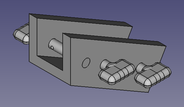
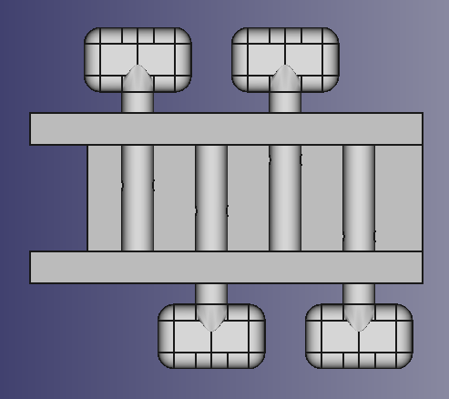
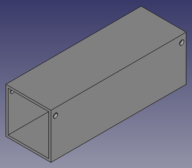
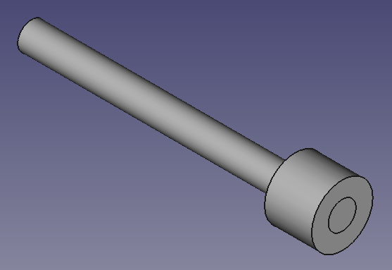
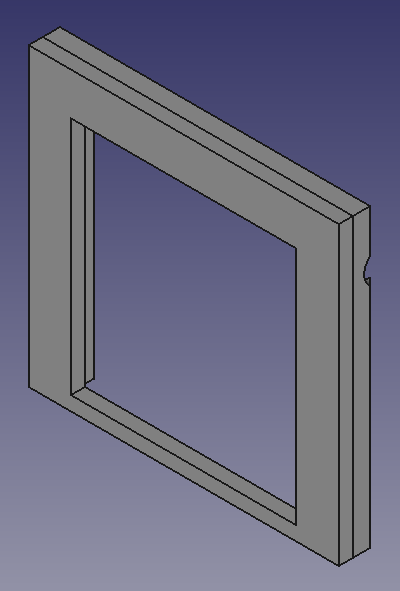
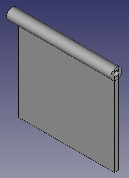
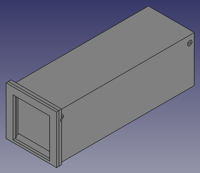
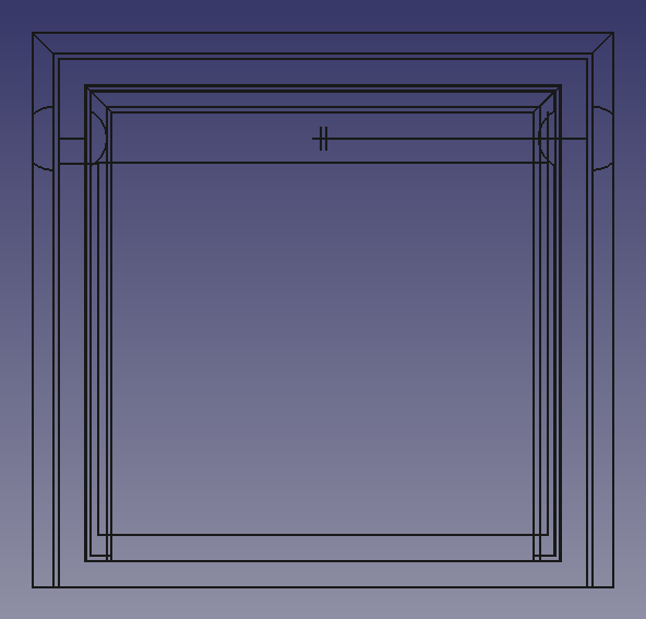
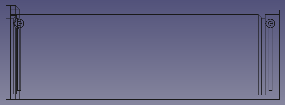
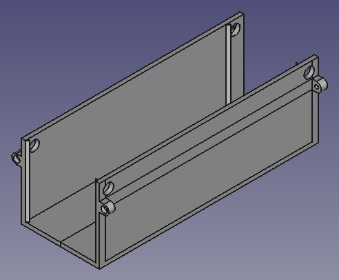
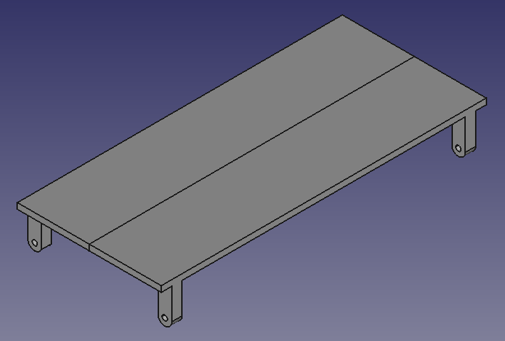
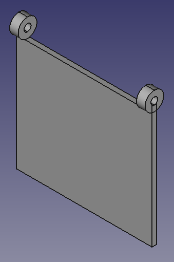
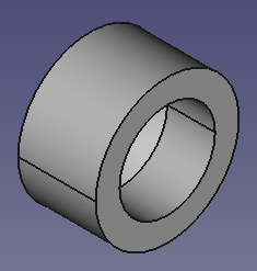
Prototypes of the pegbox and pegs were modeled in FreeCAD
Next week, I will model the fingerboard in two separate parts for printing purposes and, if time allows, will print them
To allow for more time to focus on the novel aspects of our custom viola design, we have decided to order the following parts next week, as opposed to fashioning them ourselves:
Machine head tuning pegs
Strings
Bridge
Tailpiece with fine tuners
Chinrest
Shoulder rest
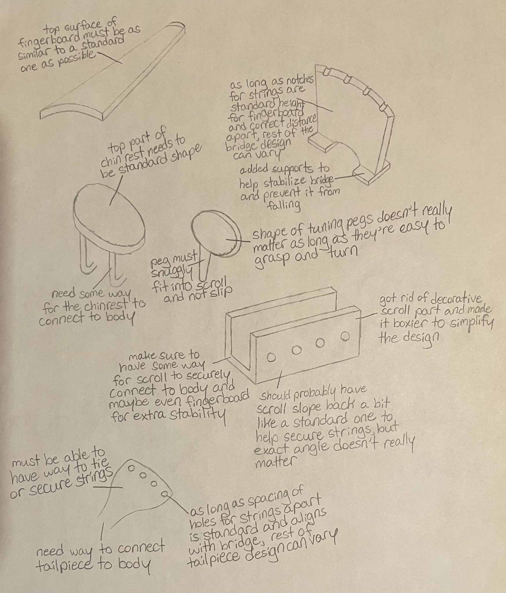
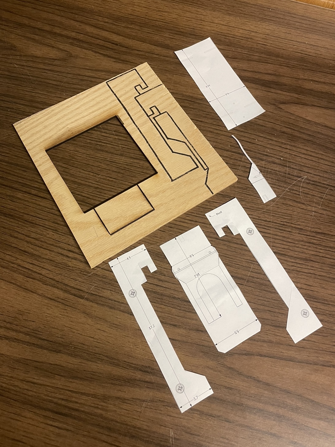
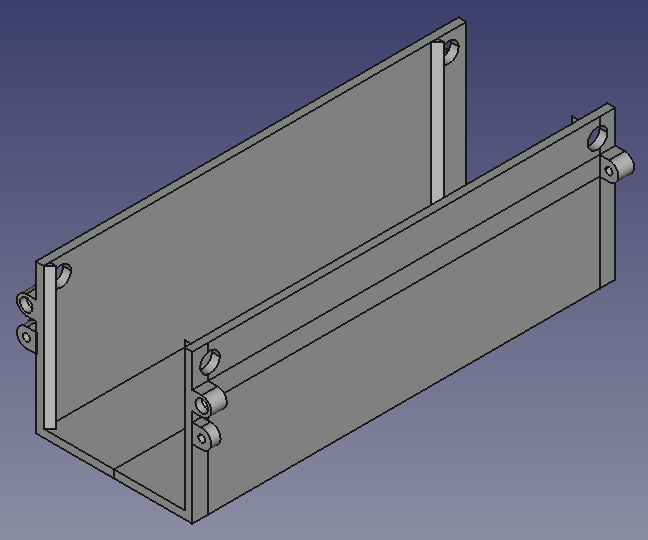
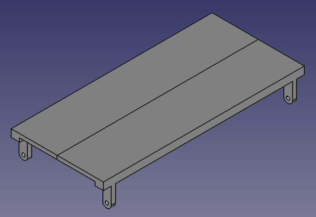
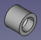
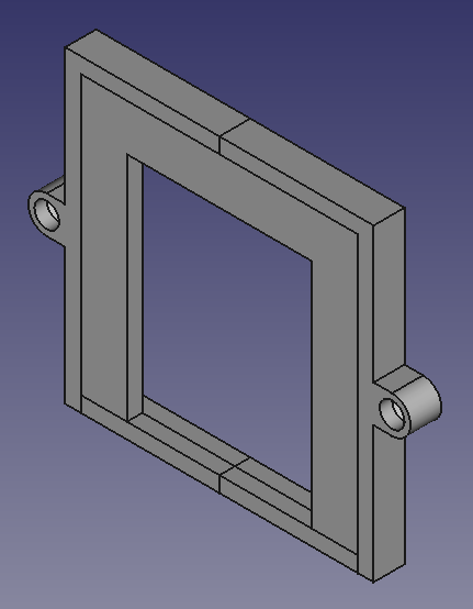
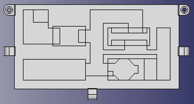
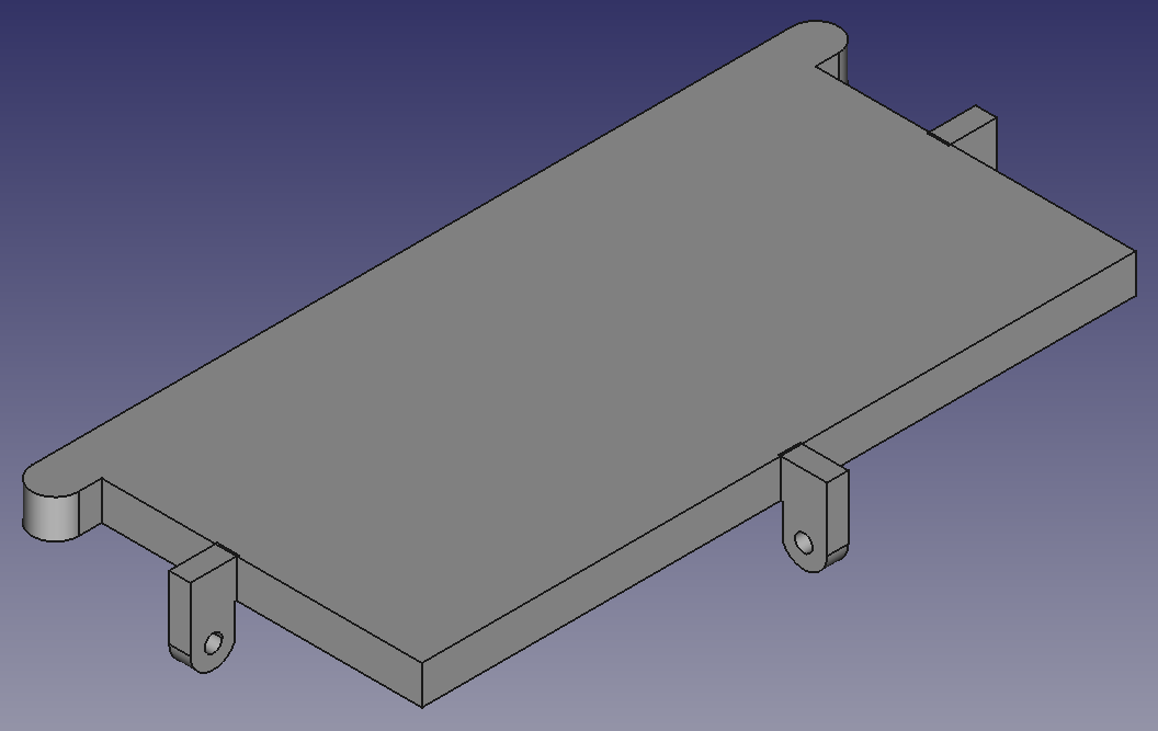
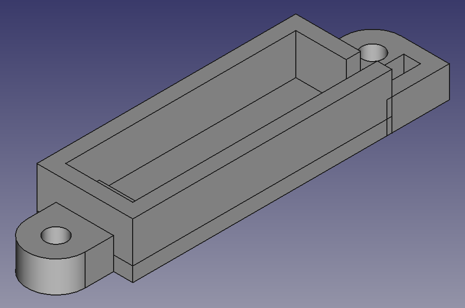
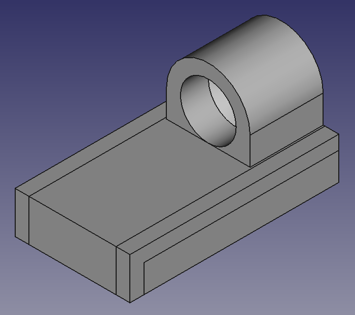
The first image below depicts some design considerations for different components of the viola, followed by isometric and top views of the assembly of the pegbox and pegs
1/28/24 – 2/3/24
Ordered most of the components for the viola, so the only non-electrical aspects we’ll need to work on are the body and pegbox
Decided to order the fingerboard as well, so I did not end up modeling it in FreeCAD
Next week, while waiting for parts to arrive, I will begin working on the modular metronome
Once the tuning pegs arrive, a new pegbox can be designed
Localized Lyme Disease Fighting
9/17/23 – 9/23/23
Met with Dr. Brzeski and Dr. Wolfe of the Forestry Dept. and learned the following:
White-footed mice are the species of mice in Michigan that are most likely to be hosts for ticks carrying Lyme disease
Local tick hotspots include Chassell and Maasto Hiihto
To administer tick repellent to small rodents, in the past, there have been experiments involving PVC pipes coated with tick repellent on the inside that gets onto to the animals’ fur as they pass through
Many types of bait, such as peanut butter and sunflower seeds, used to attract mice also entice larger animals, including bears, so it’s important for our tick repellent administration systems to be very durable
Primary design considerations at the moment include:
Use of externally applied versus oral tick preventatives
Whether sheet metal to reinforce the exteriors of the tick repellent administration systems is a viable option with our budget
Design of entry and exit doorways
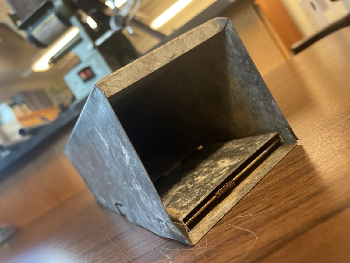
One potential option would be to have an entrance with a door that springs up and closes when a mouse walks over it, similar to that of a Sherman trap; pictured on the left side below is a Sherman trap loaned to us by Dr. Wolfe and Dr. Brzeski
Another possible choice would be to use one-way doors, such as check valve doors; below on the right side is an image of the beginnings of a prototype door using a design created by Matthias Wandel
9/24/23 – 9/30/23
Designed a prototype of the tick repellent administration system with CAD
All CAD models were created using the open-source software FreeCAD
Tolerances to facilitate assembling the system and to allow space for hot glue between components were included in the CAD models
The first four images below depict the individual components of the tick repellent administration system, while the three images following those portray the assembly
10/1/23 – 10/7/23
Current aspects of the design for the Tick Repellent Administration System (TRAS) include:
The entrance overlay is nonessential for the functionality of the TRAS, so the base component should have the ability to operate as a check valve on its own
A weight sensor could be placed just after the entrance door to record the number of mice that pass through the TRAS, but it will need to be accessible after the TRAS is deployed so that its data can be retrieved
The TRAS must be robust so that it can endure the conditions of the environment in which it will be deployed
To administer tick repellent to mice that pass through the TRAS, sponges soaked in liquid tick repellent could be secured to both sides of the base via hook and loop strips
CAD models for the TRAS components were updated to reflect these design considerations:
The base now includes a pair of triangular prisms before each door, so both the entrance and exit doors will only open one way
Since the entrance overlay is not essential for the TRAS to function, it was not included in this design iteration so the essential components could be prioritized
Components can be fastened together with a total of eight M4 x 16 mm socket head cap screws and M4 nuts, so all parts will be removable to facilitate accessing and cleaning the inside of the TRAS
To further improve the accessibility of the inside of the TRAS, the top of the base component was removed and a detachable lid was designed
The first four images below reveal the CAD models of the components, while the ensuing three images show the TRAS assembly and are followed by an image of the 3D printed doors and hinges
10/8/23 – 10/14/23
Once again, the CAD models for the TRAS’s components were updated
The entrance overlay component was brought back in this design iteration and, as with the lid, will be able to be attached and detached to the base via M4 x 16 mm socket head cap screws and M4 nuts, allowing for entrance overlays with differently dimensioned openings to be swapped out in a TRAS as needed
To adjust the opening of an overlay, one must open trasOverlay.FCStd in FreeCAD, edit the dimensions in the sketch for PadOpening named SketchOpening, and close the sketch
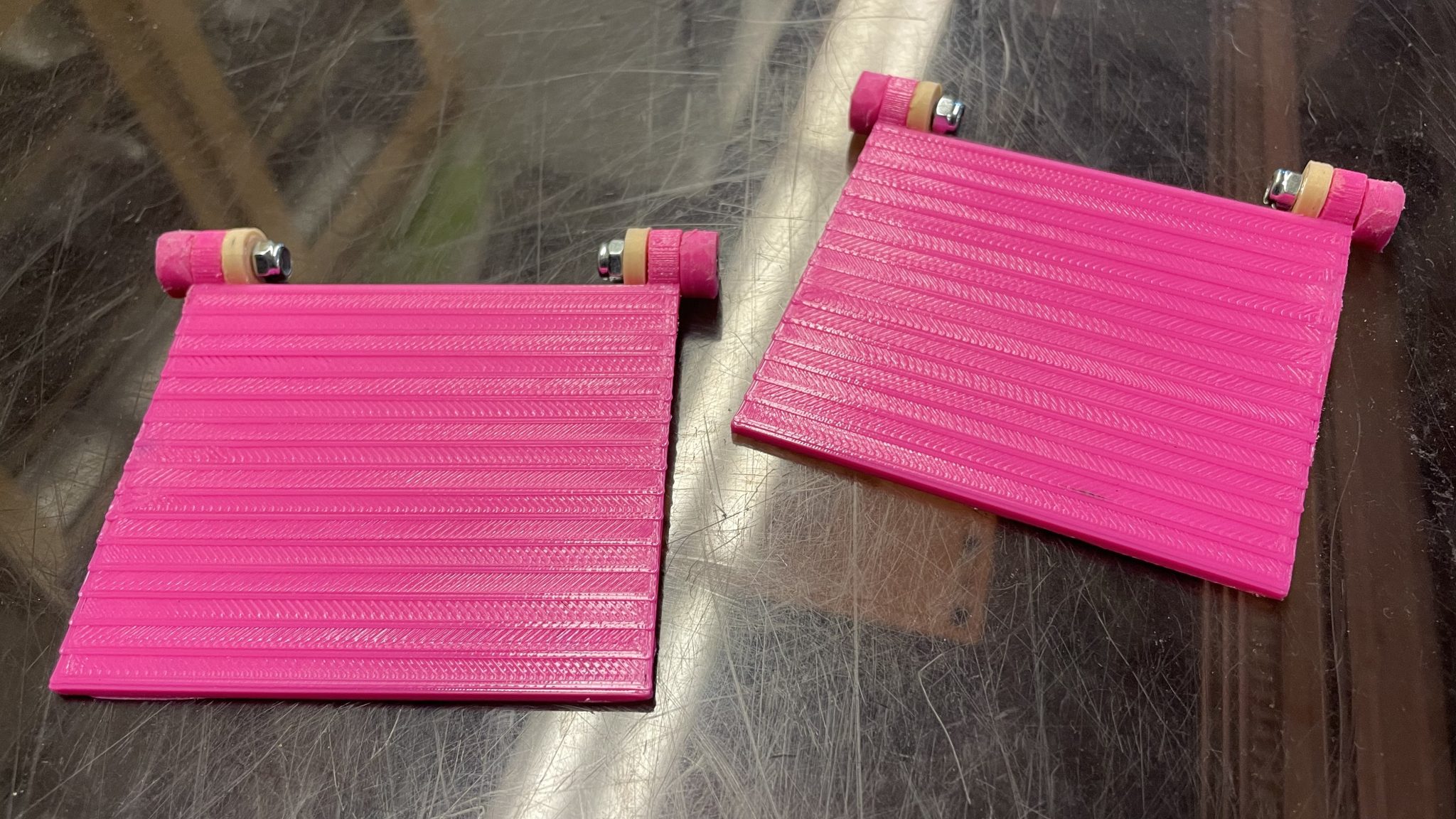
Another noteworthy adjustment was to the design of the door, so it can now be printed flush to the printer bed
The first five images below show the updated TRAS components, followed by three pictures of their assembly, and the final image exhibits prints of the overlay, one door, and all four hinges
10/15/23 – 10/21/23
Ordered components that are expected to arrive next week, including a load cell sensor for detecting when mice walk across it in the TRAS and a real-time clock (RTC) module for obtaining the precise date and time each mouse is sensed
The load cell and RTC will be used in conjunction with an Arduino Nano, which will be powered by a 9V battery
Began writing the TRAS’s Arduino code
Created an OSF repository to make all essential files for this project accessible to anyone who wishes to construct their own TRAS
Printed the second TRAS door, as shown in the image below
10/22/23 – 10/28/23
Nearly all of the components ordered the week prior arrived, apart from the load cell sensor and the HX711 load cell amplifier module
Two custom connectors to allow the Nano, RTC, and load cell amp to interface were created
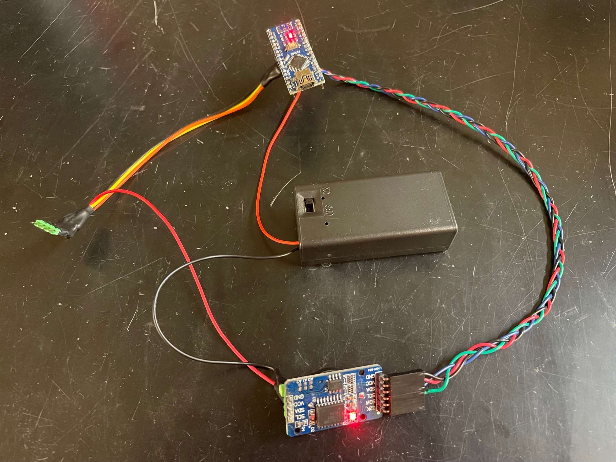
The image below depicts the Arduino Nano at the top, the 9V battery in the middle, the DS3231 RTC module at the bottom, and the pins to be soldered to the HX711 module on the left
The red/orange/yellow/black connector on the left wires the HX711’s VCC, SCK, DT, and GND pins to the DS3231’s VCC pin and the Arduino’s D3, D2, and GND pins, respectively
The unit of green/blue/red/black wires on the right connects the RTC’s SCL, SDA, VCC, and GND pins to the Nano’s A5, A4, 5V, and GND pins, respectively
10/29/23 – 11/4/23
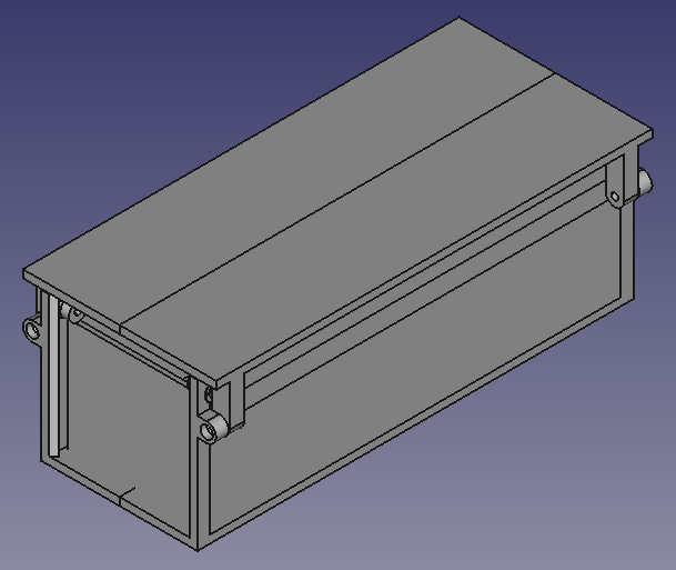
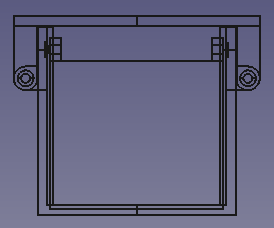
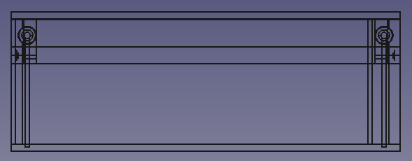
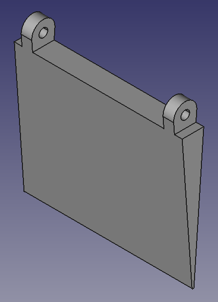
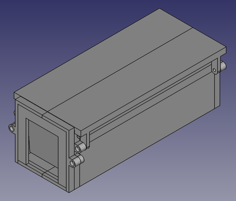
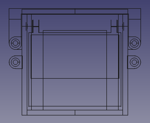
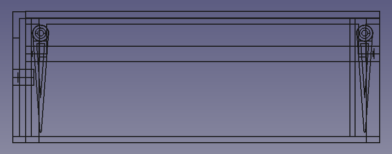
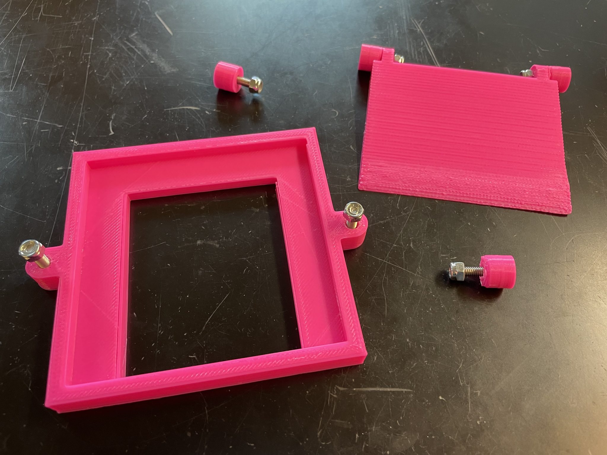
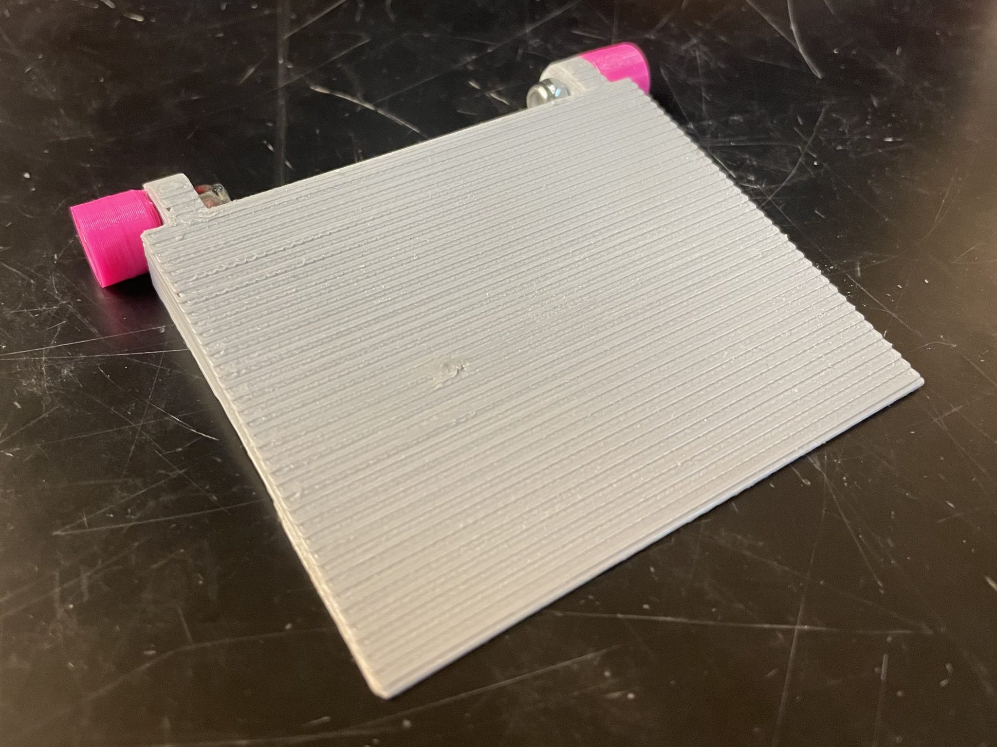
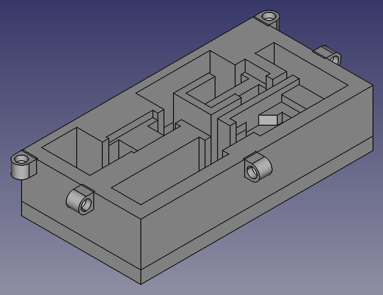
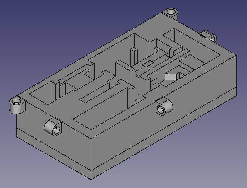
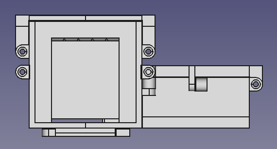
To keep the electronics and wiring protected, a case with a lid was designed to securely hold them
The base was updated so that the electronics case can be secured alongside it with two M4 x 16 mm socket head cap screws and M4 nuts
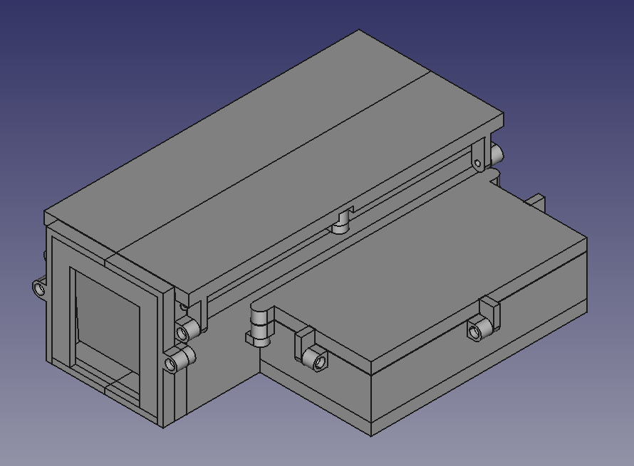
The images below exhibit the electronics case and its lid, which are to be connected with three M4 x 16 mm socket head cap screws and M4 nuts
11/5/23 – 11/11/23
A case to protect and hold the load cell was modeled and printed, while a wire shield was designed to seal off the load cell’s wires that will pass up through the base and out through the side into the electronics case
The bottom of the base was modified to accommodate the load cell and its case, and the base’s side was altered to allow the wire shield to be affixed to it and the wires of the load cell to fit through it
Two M2 x 12 mm socket head cap screws and M2 nuts are needed to secure the load cell to its case, two M4 x 16 mm socket head cap screws and M4 nuts will attach the load cell case to the base, and two M2 x 12 mm socket head cap screws will connect the base to the load cell itself
A M4 x 16 mm socket head cap screw and a M4 nut will anchor the wire shield inside of the base
The load cell case and wire shield are presented in the images below
11/12/23 – 11/18/23
Decided to include a micro SD card in the design to allow for more data to be stored, so the TRAS can be deployed for a longer period of time
To allow for more tick repellent to be administered, in addition to the sponges, wicks will be incorporated in the design, which will hang from the ceiling of the TRAS beneath a reservoir that will allow repellent to gradually drip down into the wicks
Ordered a micro SD card, a micro SD card module, wicks, and wick bases
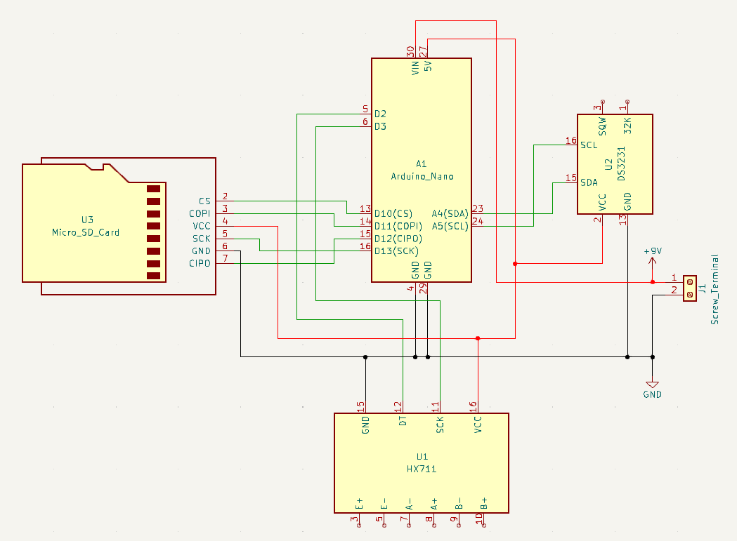
The image below depicts the schematic for the TRAS
11/19/23 – 11/25/23
Due to the HX711 module and micro SD card module each only having one voltage common collector pin and one ground pin, the electronics cannot be daisy-chained, so two three-way wire connections will be needed without the use of a circuit board
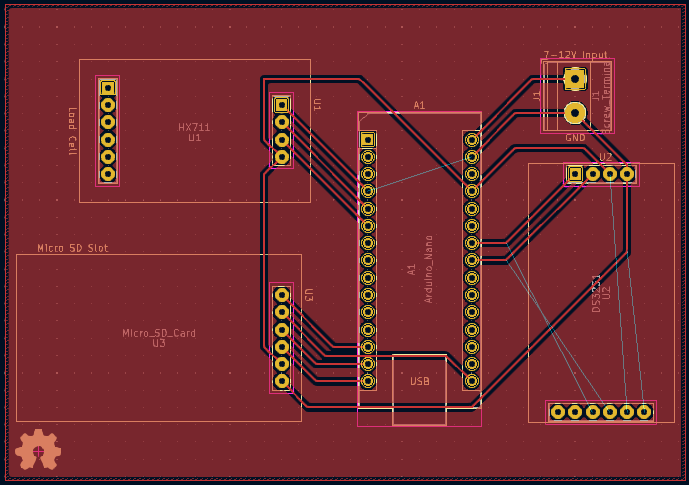
The 70 mm x 100 mm PCB shown below was designed using the open-source software KiCad
The micro SD card and its module arrived, so they were measured, and the electronics case was updated to store them
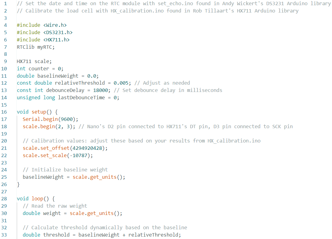
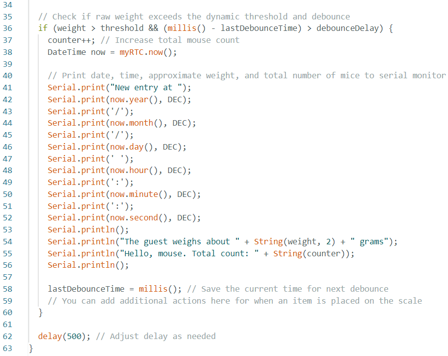
Pictured below is the updated electronics case followed by the current code for the TRAS that records when each mouse enters and the total amount of mice who have entered the system
12/3/23 – 12/9/23
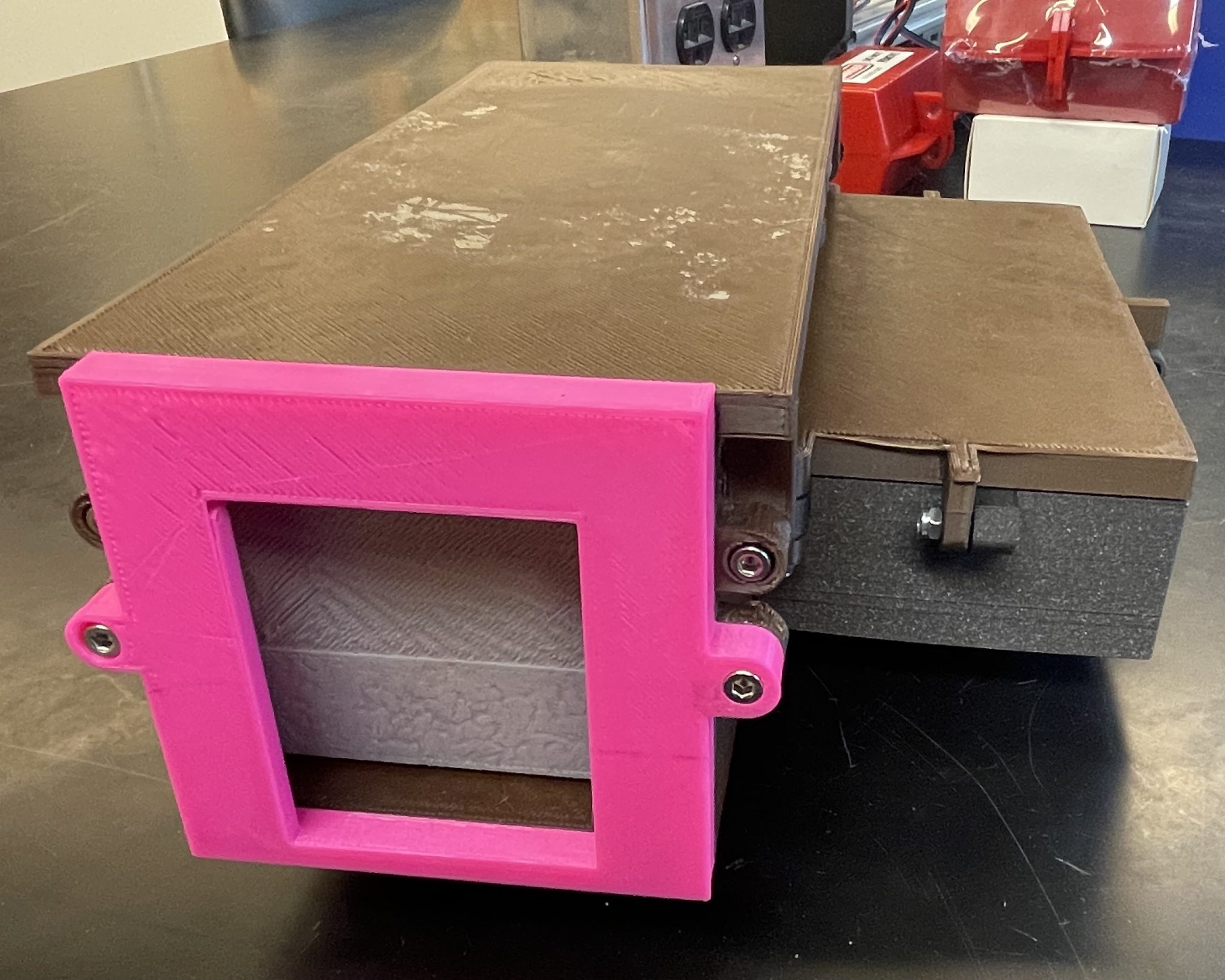
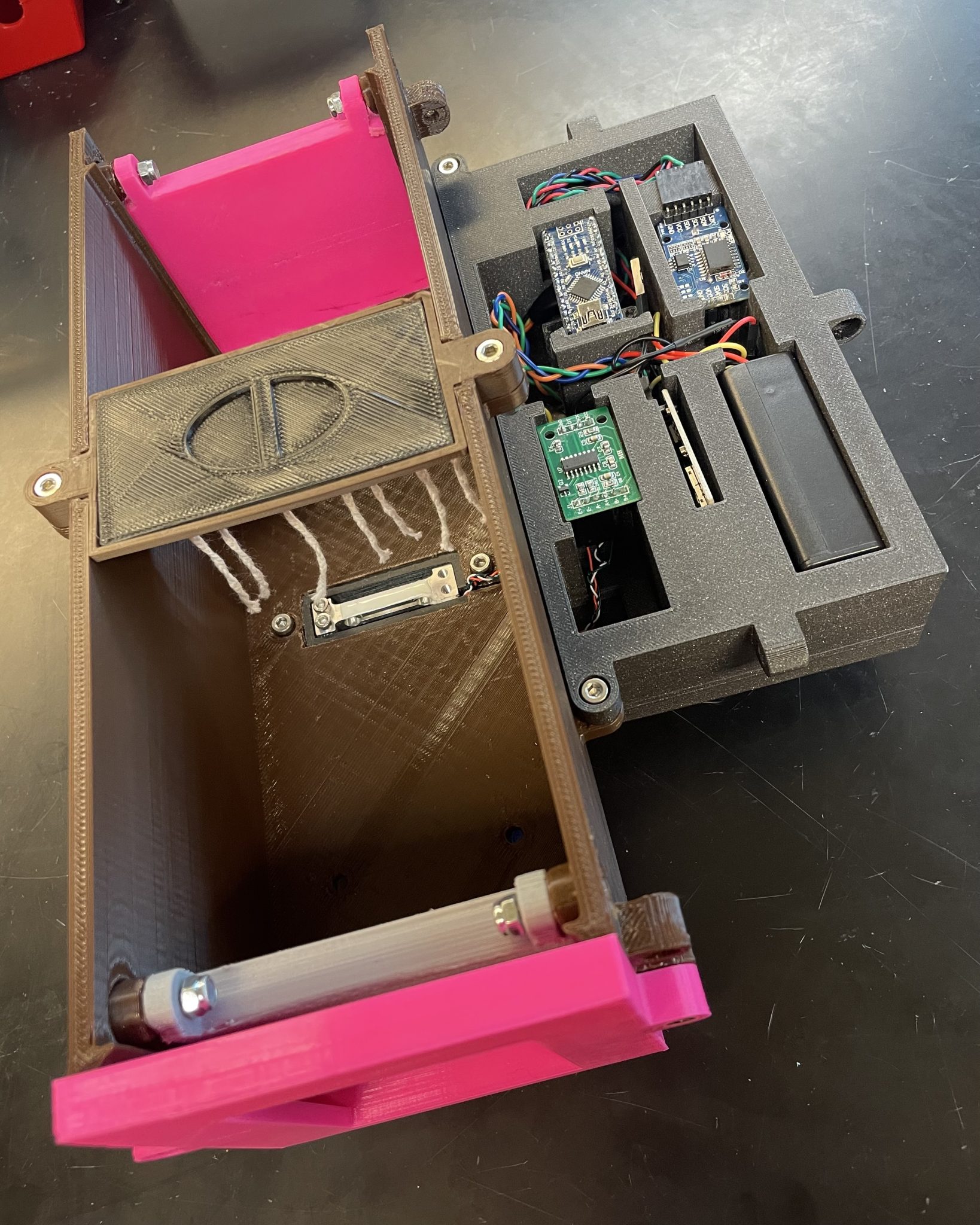
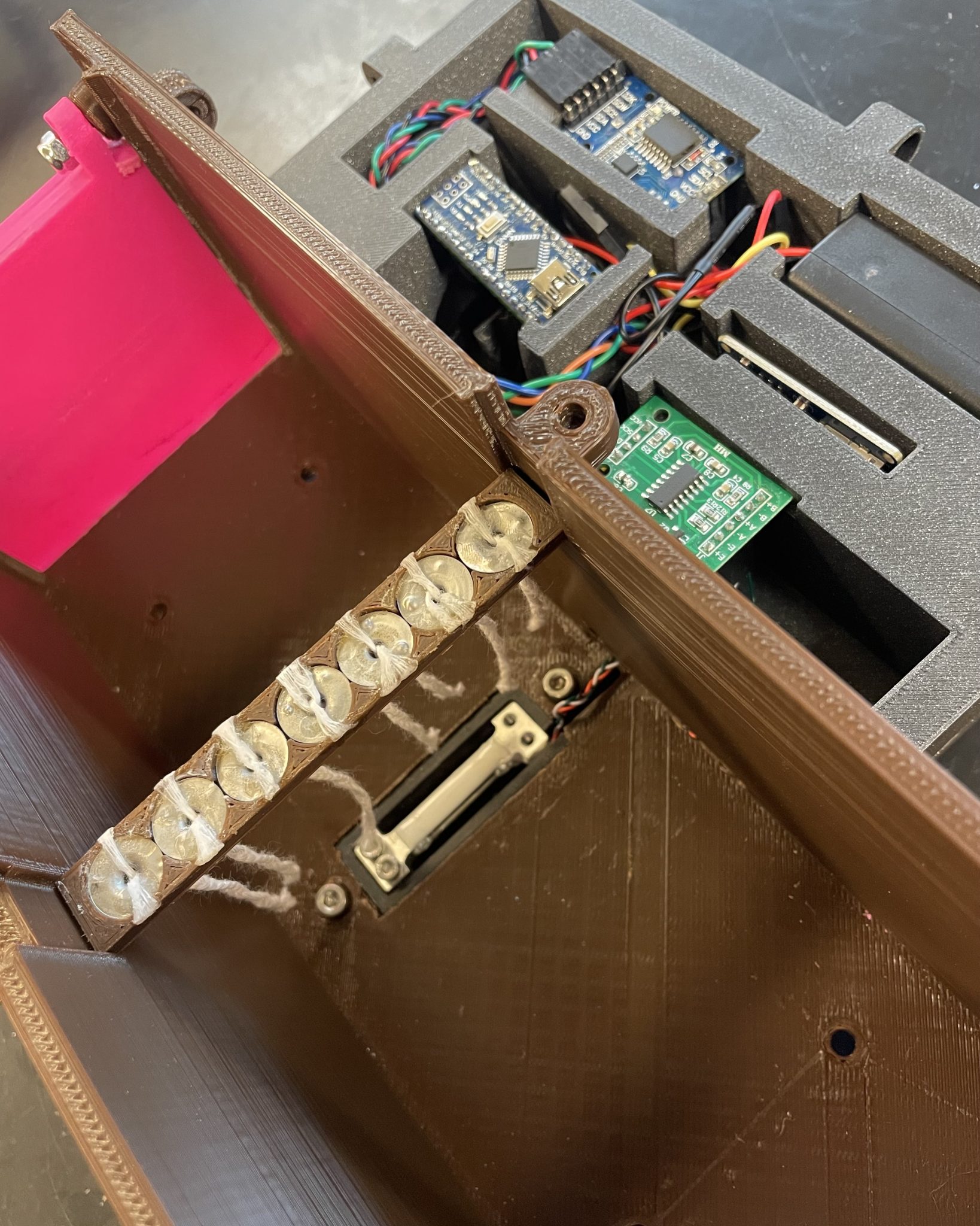
Printed the electronics case and its lid, the tick repellent reservoir and its lid, the wick holder, and the wire shield
Two three-way connectors were created, one for the VCC pins of the HX711 module, micro SD card module, and DS3231 module and another for the GND pins of the HX711 module, micro SD card module, and battery
Due to 3D printer complications, the base and its lid were not able to be printed this week
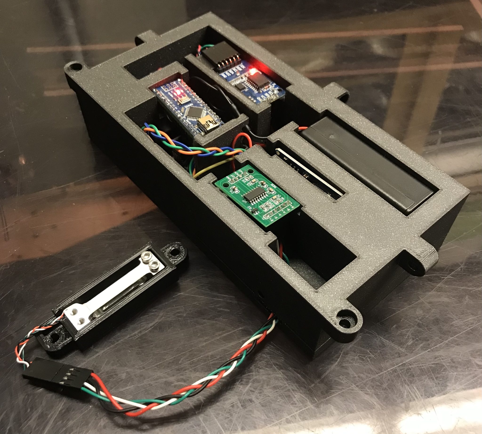
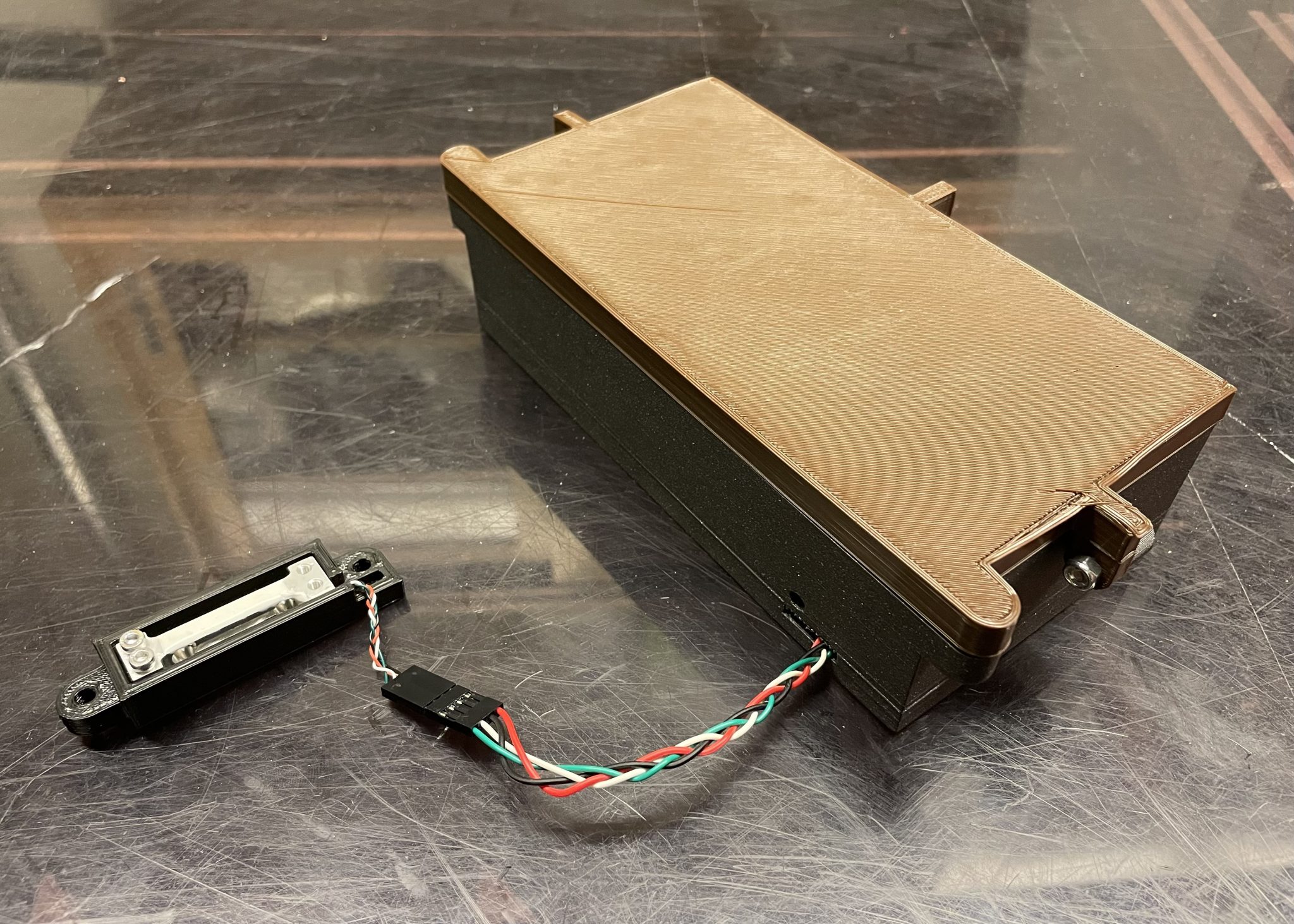
The images below display all of the TRAS’s electronics and their cases
12/10/23 – 12/16/23
The base and its lid were finally printed, so the TRAS is now complete