Background
In recent years, the number of reported Lyme disease cases in the Upper Peninsula of Michigan has increased [1]. The project Localized Lyme Disease Fighting was created with the aim of curbing this rise. Through partnership with Dr. Kristin Brzeski and Dr. Jared Wolfe of Michigan Technological University’s Forestry Department, the Tick Repellant Administration System (TRAS) was created. This device, as documented in the following report, was created by members of the Open Source Hardware Enterprise to medicate white-footed mice against disease-carrying ticks.
Design Process
As Lyme Disease Fighting was a new project this semester, there was no previously gathered work or project from which to build. The first step, then, was to understand how the device needed to operate and what possible physical manifestations could be implemented.
Members of the Forestry Department faculty were met with to discuss what they hoped to see in such a device, and foundational parameters were gathered. The functional parameters were then translated into design parameters that governed our prototyping process. The device needed to be small enough so that only mice could enter. This parameter led to the requirement that the device must have entry ways only big enough for mice. When paired with research on the size of mice expected to enter the device, a specific size was determined. Ideally the device would be deployable for days or even weeks at a time without human interference. A solution to this was check valve doors on either end of the device, allowing the mice voluntary entrance as well as exit. The device must be deployable in large quantities, so low-cost parts were chosen, and minimal sensors were implemented. The mice must want to enter the device, so it had to be camouflaged to its environment.
From the professional input that was received, as well as research independent of the Forestry Department, a requirement guideline was established (explicitly outlined in the Functional Requirements towards the end of the document) that took into account the functional requirements, mice behavior and size, and practicality. This framework allowed for the exploration of various implementations, as discussed in the following section.
Prototyping
The TRAS went through multiple stages of prototyping. While the types of doors for the device were a quick decision (check valve doors were decided upon early in the design process), other aspects were in the prototyping stage for much longer. One such part was the repellent administration system. For the actual medication there were two options: topical or oral. While keeping the cost and complexity in mind, a few options were explored.
A possible option for oral repellant administration was the release of a pellet from a dispenser which would be triggered by the mouse. However, concerns for this included the possibility of the mouse triggering the device more than once and the complexity introduced by such a system.
An option for liquid tick repellent was to have removable, solution-soaked sponges on the sides of the reservoir which the mouse would brush against as it passed through the device. Possible failures of this method included the mouse not making sufficient contact with the sponges as well as the sponges drying out too quickly.
The design settled upon was a reservoir of liquid tick repellent that would feed wicks hanging from the ceiling; the mouse would unavoidably brush the wicks as it passed under them. As a precautionary measure against under-medication, the sponge method from above was also implemented.
To record the number of mice that entered the TRAS, a sensor system consisting of a load cell, a HX711 amplifier, a SD module, and a real time clock (RTC) module were chosen. Original designs included only the load cell and amplifier module, but further development highlighted the benefit of additional components.
Before the load cell was decided upon, other sensors such as light triggered or motion triggered were explored. However, after considering factors such as weather, dirt, and debris, the load cell was chosen for its simplicity and economy.
Much trial and error went into the design of the sensor circuit and how it was to be implemented in the final design. It was decided that the electronics would be housed in their own custom case beside the base of the TRAS where mice pass through. Additionally, the circuit is modular in design, with only the load cell and the amplifier being crucial to the TRAS’s operation. This allows for a reduction in cost and complexity if needed.
The design of the circuit began with what was determined to be necessary: a sensor, a microcontroller, and a power source. An Arduino Nano was chosen for the microcontroller since they are inexpensive, and Arduino is open source. For the type of sensor, a load cell was chosen since they are also relatively inexpensive and can also be used to measure weight, providing another metric in addition to simply determining when there is a mouse. Then, a nine-volt battery was chosen to power the circuit since the Nano can accept any input from seven to twelve volts.
Since mice weigh roughly twenty grams on average, a very sensitive load cell was chosen that is capable of weighing objects between zero through one hundred grams. As force is applied to the load cell from a weight, it deforms and its resistance changes, so a HX711 module was chosen to convert the analog fluctuations in resistance into digital weight readings for the Nano.
To enhance the usefulness of the TRAS, a RTC module was incorporated into the circuit, specifically the DS3231, to accurately track the date and time of readings from mouse entries. Lastly, a micro SD module was included in the circuit to allow for a greater amount of data to be recorded.
The frame of the device was also designed in a modular fashion to allow for the removal of the roof, doors, electronics case, and door frames. With this design, the interior or the TRAS was easily accessible for operations such as cleaning or maintenance. It also allowed for the easy removal and replacement of damaged parts.
Final Design
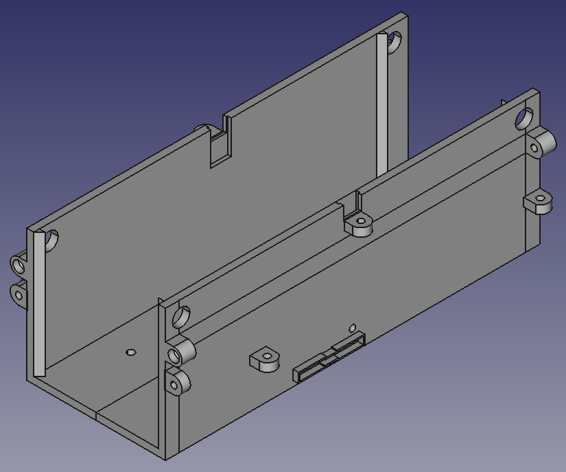
The final design can be seen in detail below. It unites the straightforward, replicable technologies of a simple microcontroller and hardware with a clever 3D printed structure and topical repellent administration system. The design is both replicable and modular allowing for a large deployment and the ability to scale down the cost and complexity to suit individual needs.
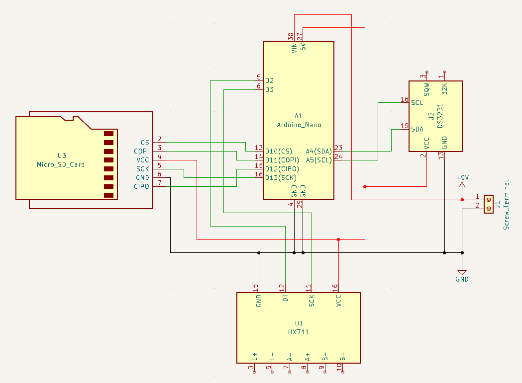
The Arduino Nano, Micro SD Card Module, DS3231 Module, HX711 Module, and battery are to be connected as shown in the schematic below. The load cell’s wires should be connected to the HX711’s pins as follows: red wire to E+ pin, black wire to E- pin, white wire to A- pin, and green wire to A+ pin.
Code
Download the three Arduino libraries found in the table below. Then, download and open trasMouseCounterWithTime.ino from the Localized Lyme Disease Fighting OSF repository at https://osf.io/zb2f9 in Arduino IDE. Follow the instructions in the comments to calibrate the load cell and set the date and time before uploading the code to the Arduino Nano in the circuit.
| Arduino Library | Link |
| HX711 | https://github.com/RobTillaart/HX711 |
| DS3231 | https://github.com/NorthernWidget/DS3231 |
| SD | https://github.com/arduino-libraries/SD |
BOM
| Part | Quantity | Cost |
| Load Cell | 1 | $6.88 |
| Arduino Nano | 1 | $26 |
| HX711 Amplifier | 1 | $6.99 |
| Micro SD Module | 1 | $5.99 |
| Micro SD Card | 1 | $6.99 |
| Real Time Clock Module | 1 | $9.99 |
| Sponges | 2 | $4.18 |
| Candle Wicks | 7 | $1.50 |
| Wood Block with Rectangular Hole | 1 | $3 |
| Wood Ramp | 2 | $2 |
| Velcro | 1 * 32 pc | $9.97 |
| M2 X 12 mm Socket Head Cap Screw | 4 | $2 |
| M2 Nut | 2 | $1 |
| M4 X 16 mm Socket Head Cap Screw | 20 | $10 |
| M4 Nut | 19 | $10 |
| Wood Screw | 8 | $5 |
3D Printed Parts BOM
| Part | Quantity | Approximate Grams of PLA per One of Each Part at 20% Infill |
| Base | 1 | 257 |
| Base Lid | 1 | 128 |
| Door | 2 | 24 |
| Door Hinge | 4 | 1 |
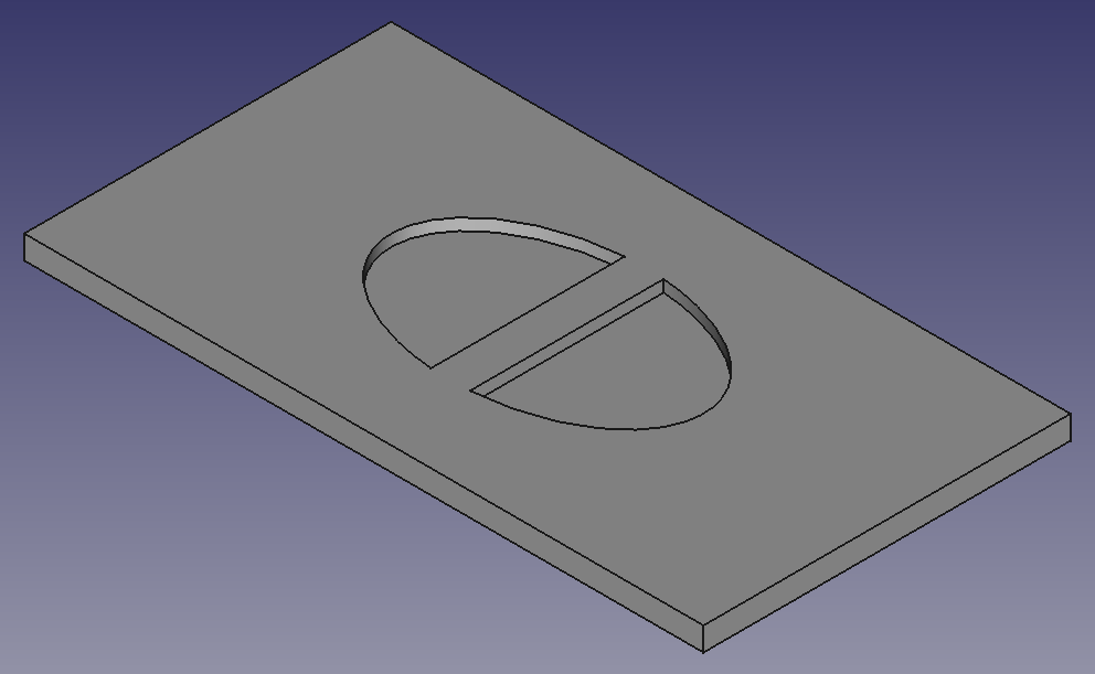
| Entrance Overlay | 1 | 28 |
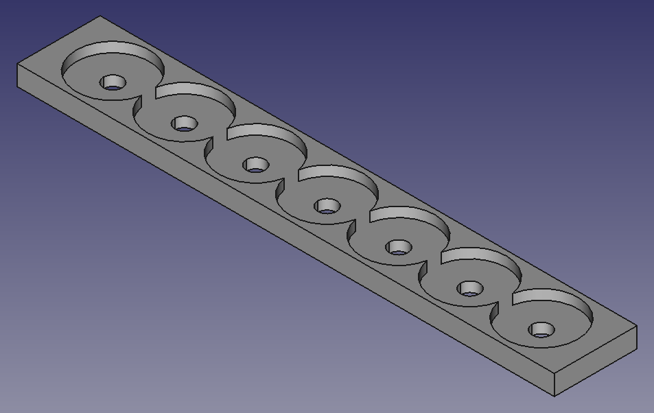
| Wick Holder | 1 | 3 |
| Reservoir | 1 | 12 |
| Reservoir Lid | 1 | 11 |
| Load Cell Holder | 1 | 7 |
| Wire Shield | 1 | 2 |
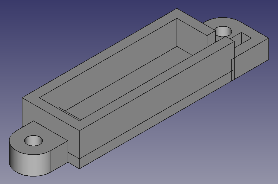
| Electronics Case | 1 | 233 |
| Electronics Case Lid | 1 | 87 |
All FreeCAD files associated with this project can be found at and downloaded from https://osf.io/x2j78/.
TRAS Assembly
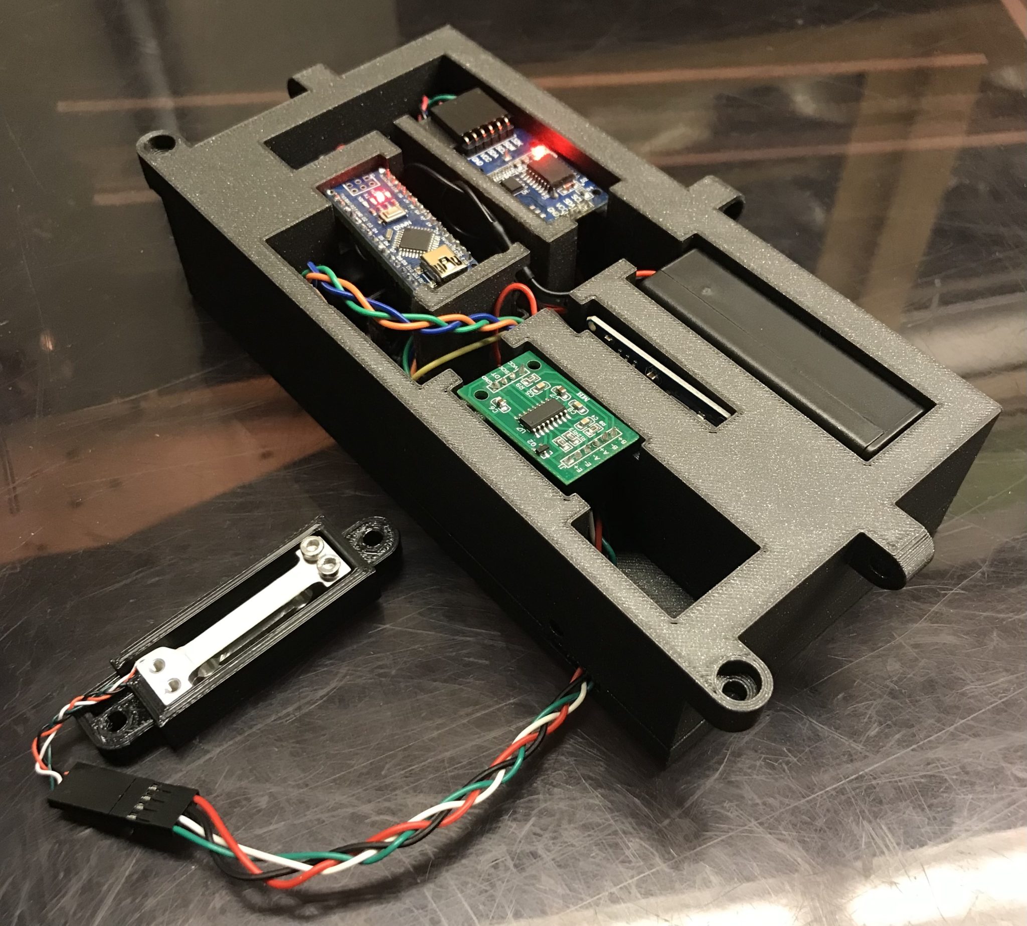
- Place the connected circuit into the electronics case as shown above and feed the wires connecting the load cell and HX711 through the hole in the side.
- Use two M2 X 12 mm socket head cap screws and two M2 nuts to secure the load cell in its holder.
- Use two M4 X 16 mm socket head cap screws and two M4 nuts to attach the load cell holder to the underside of the base, and use two M2 screws to attach the base to the load cell itself.
- Connect the load cell to the HX711 and use one M4 screw to secure the wire shield in the base so that it completely covers the load cell’s wires.
- Place Velcro along both internal sides of the base and along one side of two sponges, and soak the sponges in tick repellent before attaching them to the insides of the base.
- Use two M4 screws and two M4 nuts to attach the electronics case to the side of the base.
- Use two wood screws to connect one wooden ramp to the wooden block with the cutout, and use two more wood screws to connect the other wooden ramp to the block’s other side.
- Place the base on top of the wooden block and line up the load cell holder with the cutout, and use the remaining four wood screws to attach the base to the wooden block.
- Use two M4 screws, nuts, and door hinges to attach one door to the base, and do the same for the remaining door.
- Glue seven candle wicks to the wick holder and slide it into the slot in the middle of the base.
- Fill the reservoir with tick repellent and slide it into the slot in the base above the wick holder, and secure it with two M4 screws and nuts.
- Place the reservoir lid on top of the reservoir.
- Use two M4 screws and nuts to secure the entrance overlay to the front of the base.
- Attach the electronics case lid to the top of the electronics case with three M4 screws and nuts.
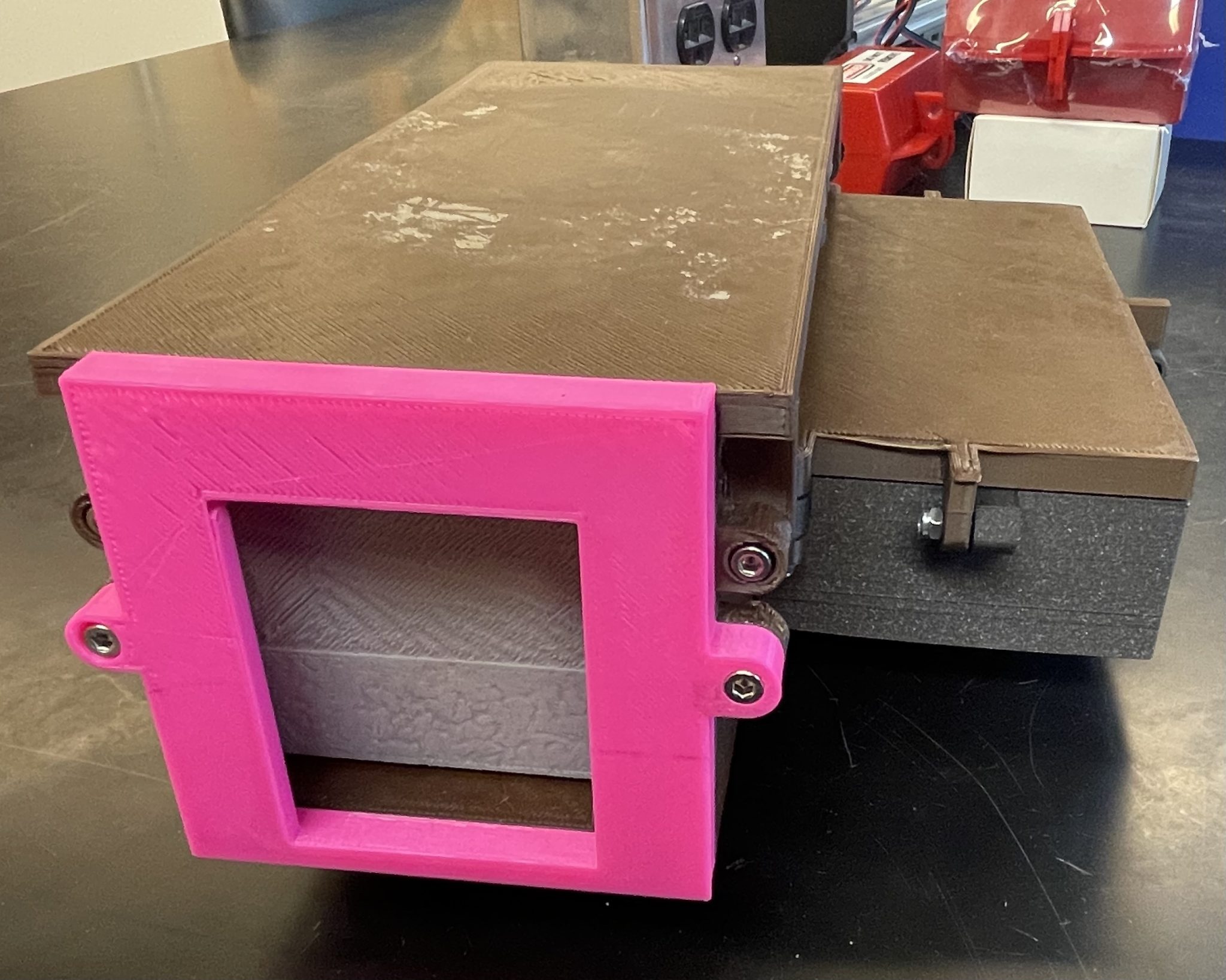
- Secure the base lid to the base’s top using the final four M4 screws and nuts, and your TRAS should resemble the one pictured below with the addition of the wooden block and ramp.
Using the Device
This device is specifically designed to be deployed in mice’s natural habitat. To use, bait the TRAS with a substance that mice are attracted to. One recommendation is to ball up a small amount of peanut butter in parchment paper. For the power source to be connected to the Arduino Nano’s VIN pin, a battery within seven to twelve volts will suffice. Additionally, the device’s reservoir will need to be filled with liquid tick repellant. After adding the liquid, ensure that there is liquid dripping from the reservoir to the wick holder. Finally, using protective gloves, soak the two sponges and adhere them to the sides of the TRAS using the adhesive fastenings. Now, the device is deployable. Use it in the area in which you want to medicate mice. When choosing the specific place to set the device, ensure that the ground allows for stakes to be pushed all the way down, as the bottom of the device will need to be flush with the ground. It is recommended that you check on the TRAS every few days.
Open Source Software Used
| Name | Link |
| Arduino IDE | https://www.arduino.cc/en/software |
| FreeCAD | https://www.freecad.org/downloads.php |
| KiCad | https://www.kicad.org/download/ |
| Cura LulzBot Edition | https://lulzbot.com/support/cura |
Functional Requirements
- A sensor will indicate when a mouse has entered the device. (15%)
- The entryway door will automatically shut when a mouse has entered the device. (10%)
- A dose of tick repellant will be accurately administered to each mouse that enters the device. (20%)
- The exit door will briefly open after tick repellant administration to release each mouse until closing again to ensure that no mice enter the device through the wrong direction. (10%)
- The amount of mice that pass through the device will be recorded. (15%)
- The device will be able to be deployed for at least one week at a time. (10%)
- The device will have fortification to protect the sensors from the elements. (10%)
- The device will include supports to help it remain upright during deployment. (10%)
Value-Added Goals
- The date and time of each mouse’s passage through the device will be recorded. (15%)
- The device will be able to be deployed for at least two weeks at a time. (10%)
- A meter will indicate the amounts of tick repellant and mouse bait remaining in the device. (5%)
- The device will be camouflaged to facilitate blending in with the surroundings of the environment it will be deployed in. (5%)
- The device will have a removable entryway attachment that can prevent larger animals from entering and allow them to enter once removed. (5%)
Reference
- Michigan Technological University. (N.D.). Tick Talk Monitoring. Michigan Technological University. Available: https://www.mtu.edu/tick-talk-monitoring/about-ticks/. Accessed: 12/10/2023.
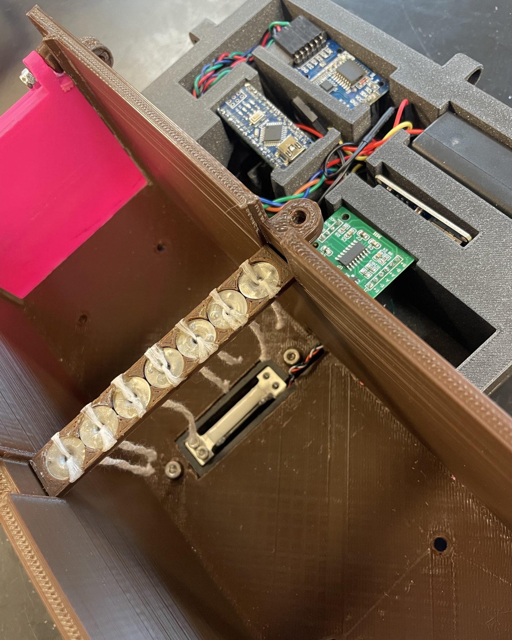
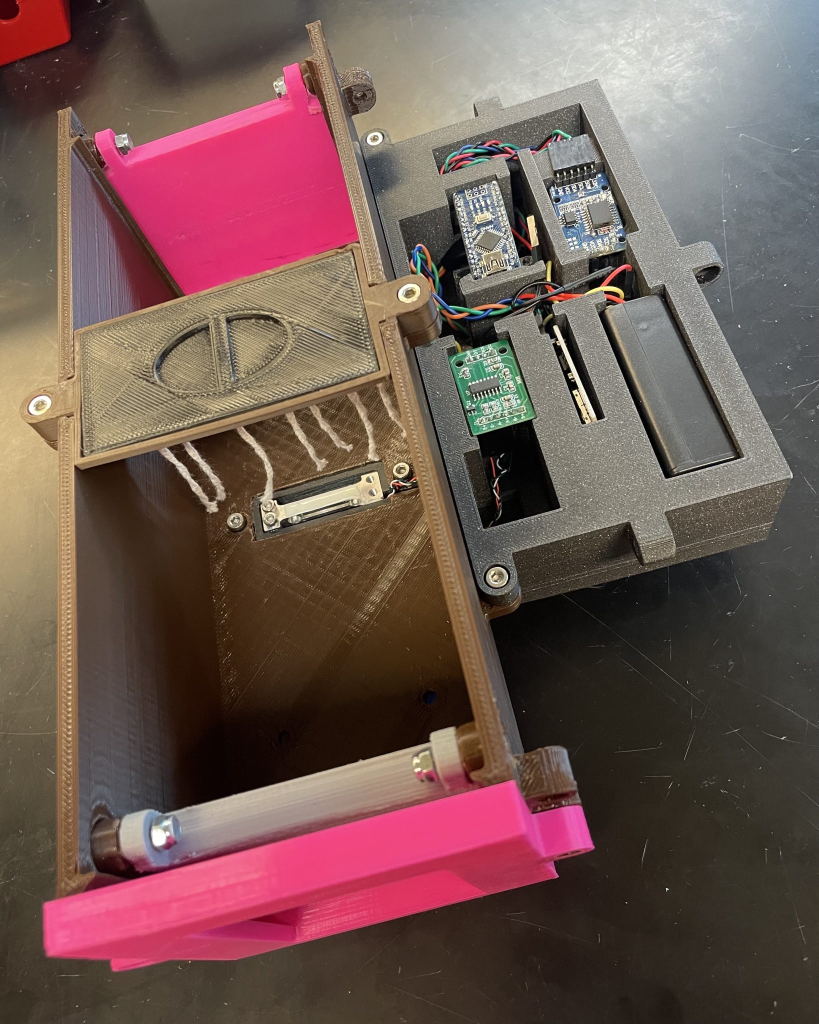
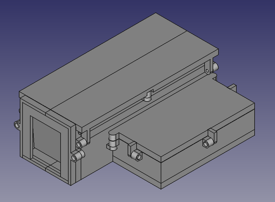
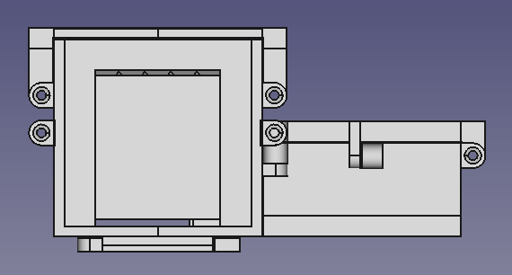
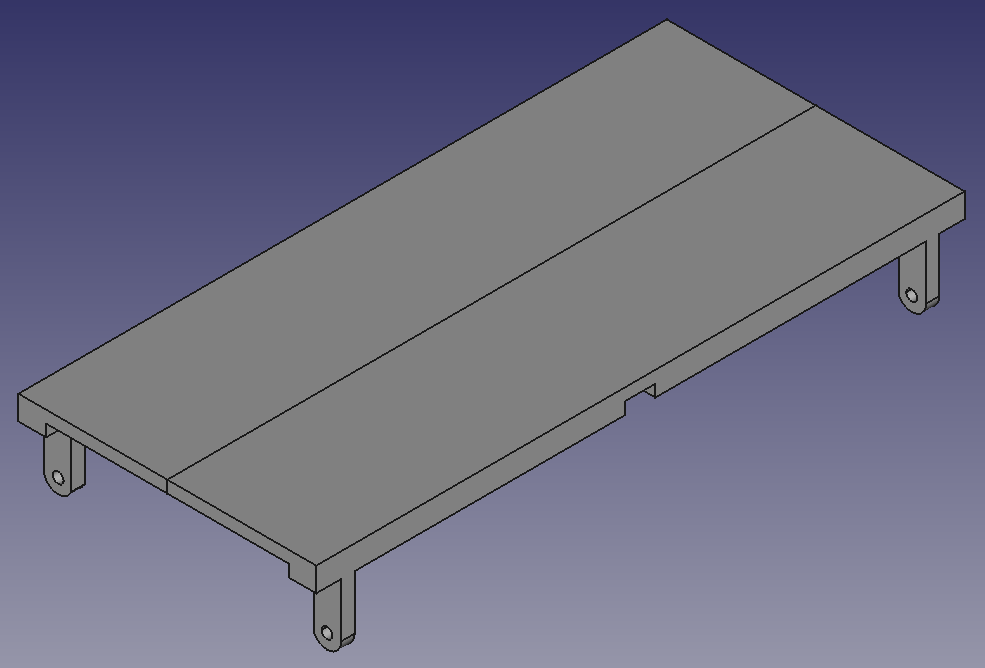
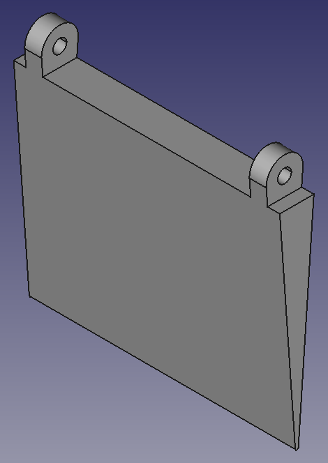
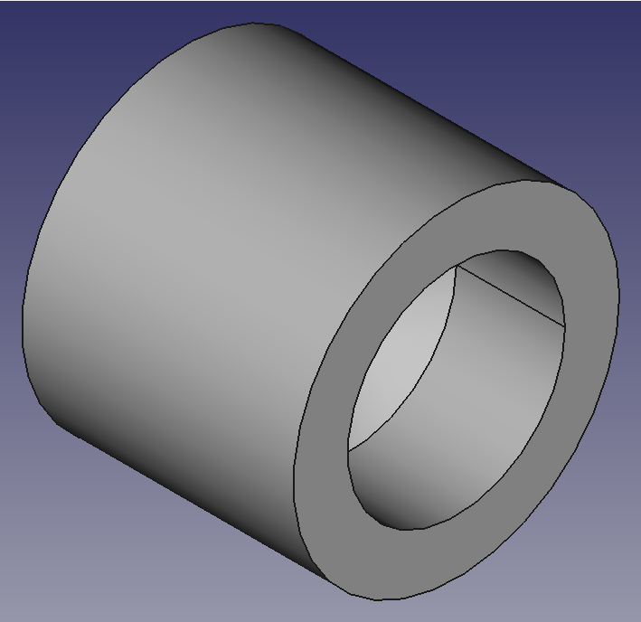
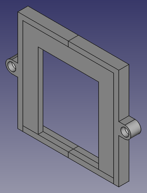
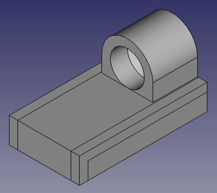
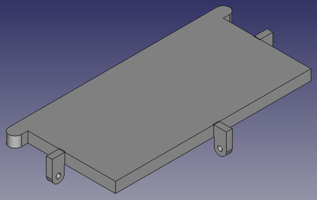
Images of CAD Models
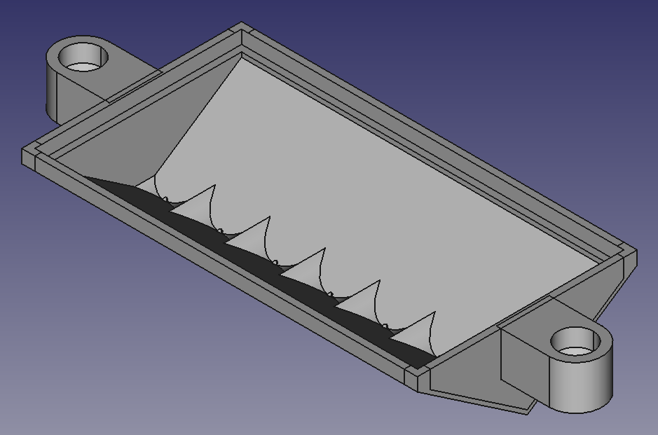
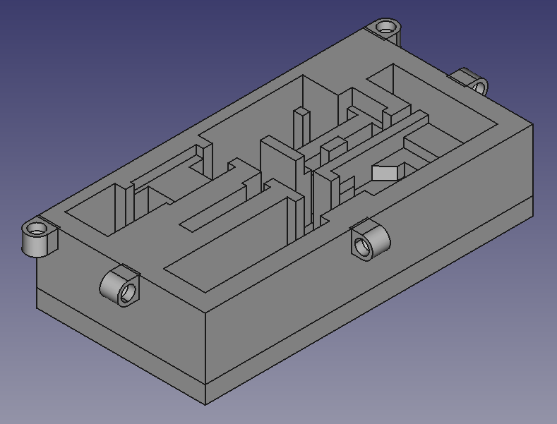
Images of Inside the TRAS