
1. Main Product Image
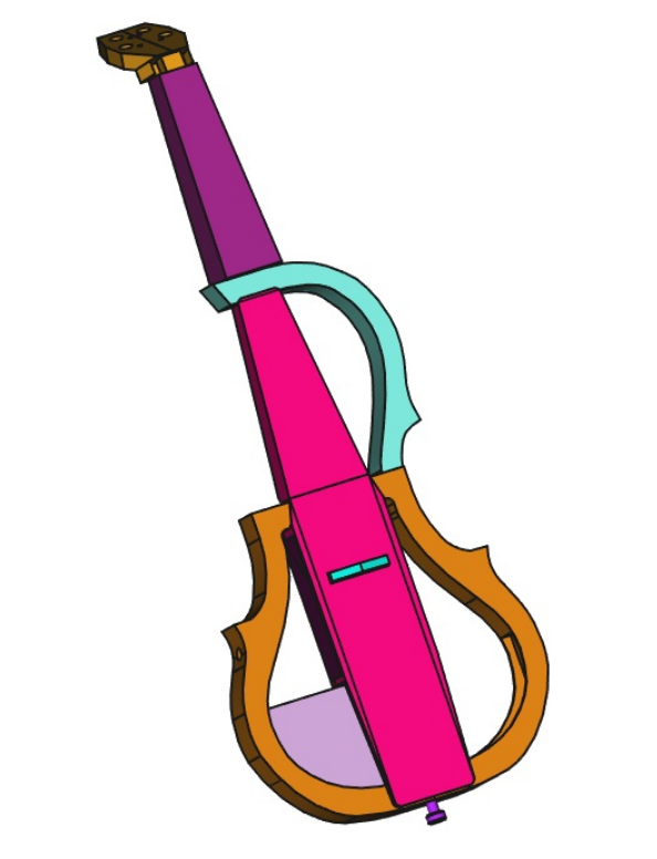
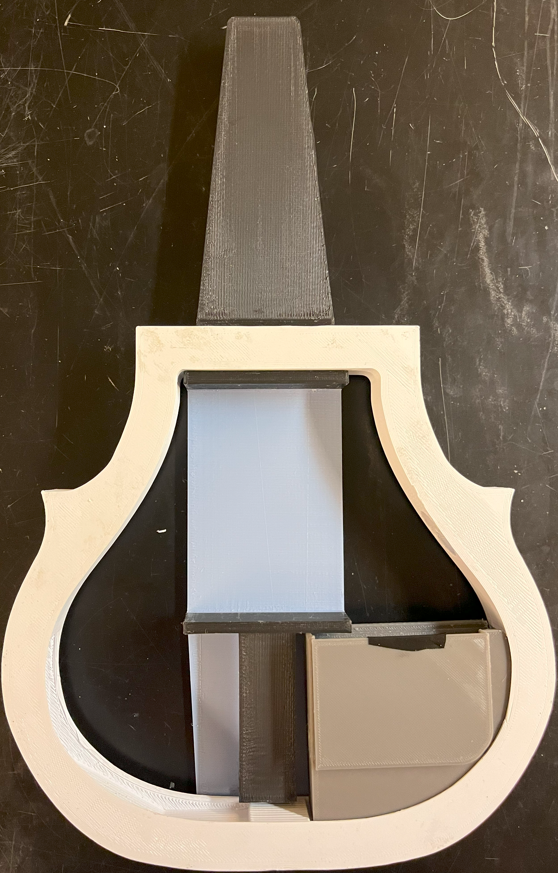
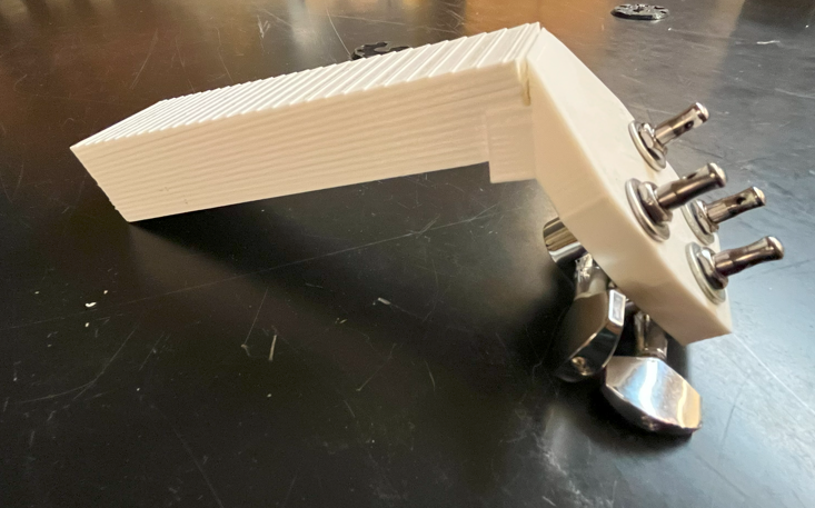
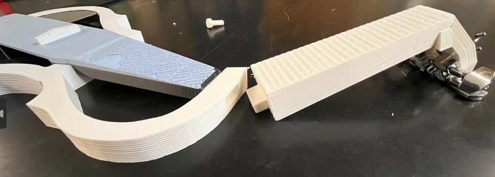
[Figure 1. Viola body and frame]
2. Project Description
This past semester, our team, Electric Viola, has been developing an open-source, 3-D printed electric viola equipped with a tuner and metronome. Our project has focused on creating a budget-friendly, open-source design to significantly reduce the cost associated with traditional string instruments and allow musicians to make their own instrument, making the experience of playing and owning a viola more accessible. We have provided a comprehensive guide that allows students and the public alike to build their own electric violas at a fraction of commercial prices. Featuring a modular metronome that functions at various tempos, a built-in tuner, traditional 15.5” viola dimensions, and piezo pickups, our project is set to deliver a fully functional, high-quality instrument that will hopefully open doors for many musicians. All files necessary for one to replicate this project can be found on our OSF page: https://osf.io/nsx86/.
3. Methodology in Brief
3.1 Viola Body
Preliminary research was heavily based around existing electric violas and string instruments in general. Measurements for our viola were taken from a physical 15.5” acoustic viola. The shape of our viola was settled upon after looking at the commercially available viola options and weighting different aspects such as replicability and aesthetics [1] [2].
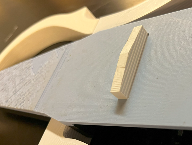
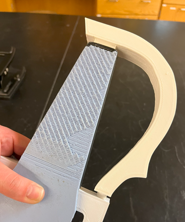
When designing the viola, one of the biggest design constraints was the limiting size of our printer. We had to work within a 270 square millimeter printing surface, but the viola was over 21” from the base to the top of the peg box. A solution was found in Japanese joinery, which is a technique of joining two pieces of (traditionally) wood without the use of screws [3].
One of the biggest considerations was string tension. String tension is defined as the force required to tune the string to the correct pitch [4]. As we came to better understand string tension, we learned that the bridge, which has a contact area of only 0.25 square inches, sees 40-45% of the overall string tension [4]. Each string contributes at most 100.2 Newtons, with the A string having the most tension and the subsequent D, C, and G strings having less (and equal) tension [5]. The bridge is in contact with all four or the strings and will feel contributions from all four; this totals to 127 Newtons or 114 psi. When choosing the appropriate filament with which to print, we chose polyplastic acid (PLA), which has a stress at yield strength of 8840 psi [6]. In addition to its strength, PLA is also beginner-friendly and common, making it an ideal choice for an open-source design [7].
3.2 Pickups
There was a lot of different research that went into this. Initial research explored types of pickups used in the audio industry, such as piezo and humbucker pickups. The piezo pickups are fairly cheap and still give decent sound quality [8], whereas humbucker pickups give better sound quality but cost more and are more complicated to create. Due to the significant cost difference between the two types, it was decided to see if the piezo pickups were successful before looking more into the humbucker configuration.
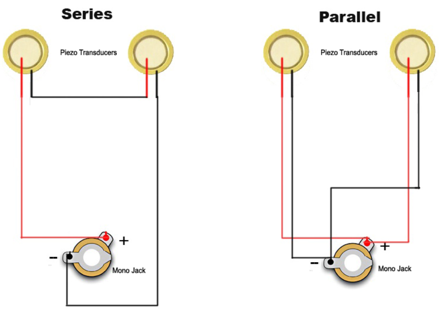
[Figure 2: Types of Piezo Configurations] [9]
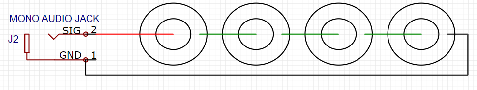
[Figure 3: Final Piezo Configuration]
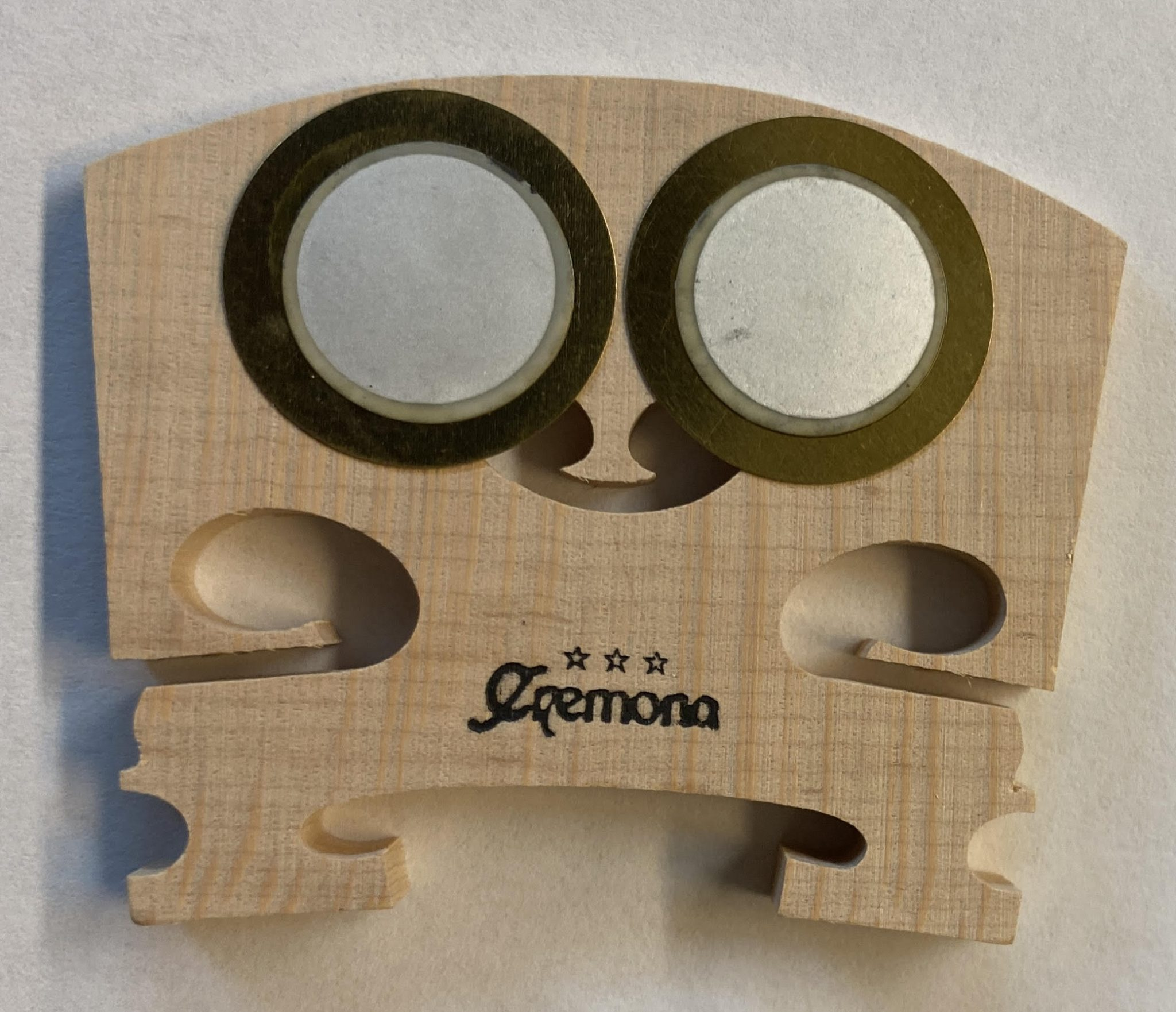
[Figure 4: Final Piezo Location on Viola]
The next topic researched was different configurations the piezos could be in. Figure 2 shows the basic connections for this. It was determined that there was no single correct configuration out of the two, and it should be determined through testing [9]. A test was conducted on a traditional viola with two configurations, one was three piezo buzzers in series and the other was three piezo buzzers in parallel. While both were successful, the series configuration picked up significantly more volume over various locations. Another decision that needed to be made was regarding the location of these piezos on the instrument. The three piezos were tested on different locations of a traditional viola such as on the fingerboard, on the body between the bridge and fingerboard, on the bridge, and combinations of all of the above. Through this experiment, it was determined that the three piezos on either side of the bridge provided the best sound quality from the instrument. In fact, this worked so well that a fourth piezo was added so both sides of the bridge have two. Figures 3 and 4 above give visuals for the final configuration and layout of the pickup system that will be used.
The creation of this circuit is fairly simple and cheap, consisting of five total components: an audio jack and four piezo buzzers. The only problem is that these components are typically bought in bulk, so it’s sometimes difficult to purchase them in smaller quantities. The tools needed to complete this subpart of the project include wire strippers, a soldering iron, a spool of solder, and a spool of wire.
3.3 Modular Metronome
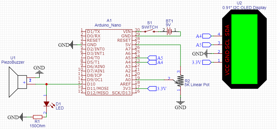
[Figure 5: Final Metronome Circuit]
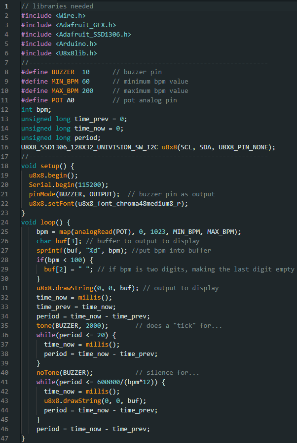
[Figure 6: Arduino Code for Metronome]
The research phase for the modular metronome involved looking into different types of digital metronomes. Mechanical metronomes and many digital kinds were immediately eliminated due to space constraints. Since this metronome circuit is supposed to fit into a small housing attachable to the viola, it ideally needs to be as small as possible while still having features like displaying the tempo and user input to change the tempo being outputted. Additionally, a digital metronome has the potential for customization and user upgrades. After much consideration, it was decided that a circuit style similar to [10] should be implemented. This was built on a breadboard and tested at a constant tempo to ensure the circuit was designed properly.
The code was also a point of research, as far as how the Arduino IDE works and what libraries will be needed for this project. Sources [11] and [12] provided great insight into this during the code development process. Testing the code was a lot of trial and error, as well as reorganizing the code when needed to be as efficient as possible. The metronome accuracy relies on how fast the code can be run, so minimizing code was essential.
Figures 5 and 6 show the final revisions of the metronome schematic and the code for the semester. The way the two work together is the 5K linear potentiometer delivers a voltage between 0V and 5V to Analog 0 (A0) on the Arduino. The code converts this voltage to a tempo between 60 beats per minute and 200 beats per minute. Arduino code writes this value to the OLED display using the A4 and A5 pins as Serial Data (SDA) and Serial Clock (SCL), respectively. The Digital 10 (D10) pin is an output for the Arduino that controls the voltage delivered to the LED and piezo buzzer. The code calculates the period that the pin is hot and the period when it provides 0V, which then produces the “ticks” heard and seen from the buzzer and LED. The 9V battery is there to power the Arduino and the switch is to cut off power to the Arduino, turning off the circuit.
The major components of this circuit include an Arduino Nano, an OLED display, a potentiometer, and a buzzer, as specified in the respective bill of materials. It’s important to note the cost of the Arduino and OLED display, as they are the most expensive components for the circuit. The tools needed to complete this subpart of the project include the Arduino IDE, a USB 2.0 Cable A to Mini B, wire strippers, a breadboard, a soldering iron, solder, and a spool of wire.
3.4 Modular Tuner
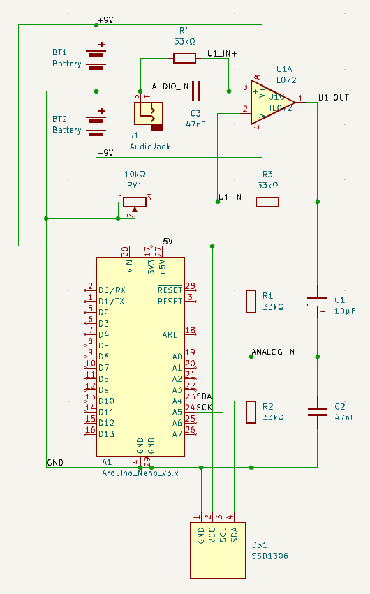
Figure 7: Tuner Schematic
To offer someone playing the electric viola the convenience of knowing the frequency of the note they’re playing without needing an external device, a modular tuner can be included by anyone choosing to replicate this project. The tuner can be secured within a case that connects to the body of the viola, and frequency is displayed in the upper right portion of the body at an angle allowing the player to easily view the display. The program to upload to an Arduino Nano for the tuner is in Arduino IDE, and the Adafruit SSD1306 library needs to be installed.
The tuner circuit is in parallel with the piezoelectric discs, and the audio signal is fed into the non-inverting input of an operational amplifier, replicating the circuit design of [13]. The gain of the op amp can be adjusted with a potentiometer, and for the electric viola, the gain was set to approximately 10. After the audio signal is amplified, a voltage divider utilizing the 5V from the Nano and two equivalent resistors provides it with a 2.5V DC offset. The gain was adjusted to have the range of the signal within the 0V to 5V input voltage range of the Nano.
After the signal is input to one of the Nano’s analog pins, using modified code from [14], the frequency is calculated and output to an OLED display. The ADC interrupt is triggered every 26μs to sample the audio signal at a rate of approximately 38.5kHz. Whenever a rising edge of the signal passes 2.5V, the length of the period is determined using a timer, which is then reset. The period of the signal is then used to determine its frequency, which is ultimately depicted on an OLED display to allow a player to see the frequency of the note currently being played.
To filter out 60Hz noise that was being picked up by the piezoelectric discs, a high pass filter was included after the piezos and before the op amp. Since the lowest note on a viola is 131Hz, and to account for the open C string possibly being too low when tuning, a frequency well below that was chosen to be the cutoff frequency. Using standard resistor and capacitor values—33kΩ and 47nF—and the cutoff frequency formula, 103Hz was decided upon.
4. Bill of Materials (BOM)
4.1 Viola Body
Table 1: Printed Viola Parts
|
Part |
Quantity |
Infill |
Infill Pattern |
Printer |
Wall Count |
|---|---|---|---|---|---|
|
body |
1 |
70% |
cubic |
Creality |
4 |
|
frameBottom |
1 |
70% |
cubic |
Lulzbot |
4 |
|
frameTopRight |
1 |
70% |
cubic |
Lulzbot |
4 |
|
topBody |
1 |
70% |
cubic |
Lulzbot |
4 |
|
tailpiecePeg |
1 |
100% |
cubic |
Lulzbot |
4 |
|
bridgeAttachTriangle |
1 |
70% |
cubic |
Lulzbot |
4 |
|
electronicsCaseLeft |
1 |
20% |
cross |
Lulzbot |
2 |
|
electronicsCaseRight |
1 |
20% |
cross |
Lulzbot |
2 |
|
caseLid |
2 |
10% |
grid |
Lulzbot |
2 |
|
neck |
1 |
70% |
cubic |
Lulzbot |
4 |
|
batteryHolder |
1 |
70% |
cubic |
Lulzbot |
4 |
|
head |
1 |
70% |
cubic |
Lulzbot |
4 |
Table 2: Non 3D Printed Viola Parts (quantity for all is 1)
|
Part |
Quantity |
Total Cost |
Purchasing Link |
|---|---|---|---|
|
15.5” Fingerboard |
1 |
$14.99 |
|
|
Bridge |
1 |
$5.95 |
|
|
Tailpiece |
1 |
$13.95 |
|
|
Chinrest |
1 |
$7.95 |
|
|
Shoulder Rest |
1 |
$9.99 |
|
|
Tuning Machine |
4 (2 left, 2 right) |
$9.99 |
|
|
A, D, G, and C Strings |
1 (set of four) |
$8.17 |
4.2 Pickups
Table 3: Pickup Circuit BOM
|
Part Number |
Description |
Quantity |
Cost |
Purchasing Link |
|---|---|---|---|---|
|
B00SWO6VJ0 |
20mm Diameter Piezoelectric Discs |
4 |
$6.99 |
|
|
B08MT66VPX |
0.25” Female Mono Audio Jack |
1 |
$9.88 |
4.3 Modular Metronome
Table 4: Metronome Circuit BOM
|
Part Number |
Designator |
Description |
Quantity |
Total Cost |
Purchasing Link |
|---|---|---|---|---|---|
|
A000005 |
A1 |
Arduino Nano |
1 |
$9.99 |
|
|
RA1113112R |
S1 |
Unpolarized Switch |
1 |
$0.67 |
|
|
6LR61-1B |
BT1 |
9V Battery |
1 |
$2.00 |
|
|
EK2146 |
U1 |
Piezo Buzzer |
1 |
$7.28 |
|
|
B09MZ8DW4R |
U2 |
0.91” I2C OLED Display |
1 |
$12.99 |
|
|
CF12JT150R |
R1 |
150Ω Resistor |
1 |
$0.10 |
|
|
PTN16-D05120K1B1 |
R2 |
5KΩ Linear Potentiometer |
1 |
$1.20 |
|
|
151031VS06000 |
D1 |
Green LED |
1 |
$0.17 |
|
|
36-232-ND |
– |
Battery Connector |
1 |
$0.52 |
4.4 Modular Tuner
Table 5: Tuner BOM
|
Part Number |
Designator |
Description |
Quantity |
Unit Cost |
Total Cost |
|---|---|---|---|---|---|
|
A1 |
Arduino Nano |
1 |
$24.90 |
$24.90 |
|
|
U1 |
TL071 Op Amp |
1 |
$0.63 |
$0.63 |
|
|
DS1 |
OLED 128×32 Display |
1 |
$4.82 |
$4.82 |
|
|
RV1 |
10 kΩ Linear Taper Potentiometer |
1 |
$1.03 |
$1.03 |
|
|
R4 |
33 kΩ Resistor |
4 |
$0.10 |
$0.40 |
|
|
C1 |
10 μF Electrolytic Capacitor |
1 |
$4.13 |
$4.13 |
|
|
C2, C3 |
47 nF Ceramic Capacitor |
2 |
$0.25 |
$0.50 |
|
|
BT1, BT2 |
2 |
$4.63 |
$9.26 |
||
|
2 |
$3.00 |
$5.99 |
|||
|
2 |
$3.56 |
$7.12 |
|||
|
1 |
$0.20 |
$0.20 |
|||
|
1 |
$3.29 |
$3.29 |
5. Tools Used
5.1 Viola Body
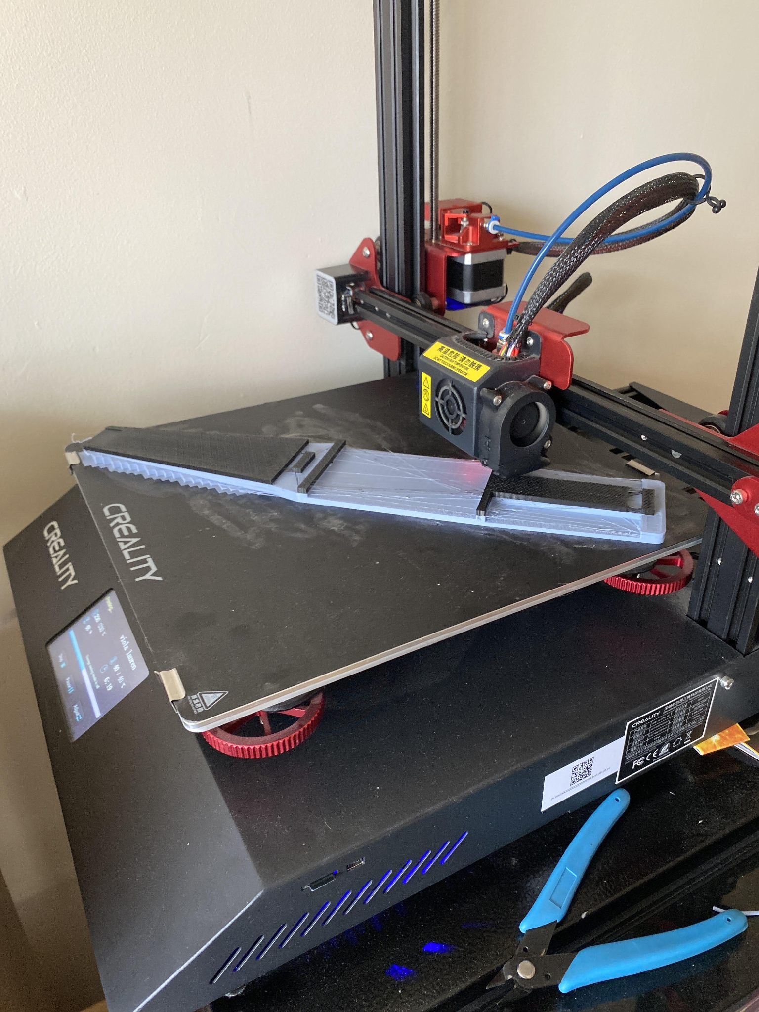
[Figure 8: Creality printer]

[Figure 9: Lulzbot printer for body]
The following software was used:
5.2 Pickups
Table 6: Tools Used for the Pickups
|
Part Number |
Description |
Quantity |
Unit Cost |
Link |
|---|---|---|---|---|
|
404080001 |
Wire Strippers |
1 |
$4.90 |
|
|
N/A |
Solder Spool |
1 |
$7.99 |
|
|
AO469 |
Soldering Iron |
1 |
$29.99 |
|
|
N/A |
22 AWG Wire Spool |
1 |
$9.49 |
5.3 Modular Metronome
Table 7: Tools Used for the Metronome
|
Part Number |
Description |
Quantity |
Unit Cost |
Purchasing Link |
|---|---|---|---|---|
|
404080001 |
Wire Strippers |
1 |
$4.90 |
|
|
N/A |
Solder Spool |
1 |
$7.99 |
|
|
AO469 |
Soldering Iron |
1 |
$29.99 |
|
|
N/A |
22 AWG Wire Spool |
1 |
$9.49 |
|
|
2183-352-ND |
Breadboard |
1 |
$5.95 |
|
|
N/A |
Arduino IDE |
1 |
$0 |
|
|
SC-2ANK003F |
USB 2.0 Cable A to Mini B |
1 |
$2.80 |
5.4 Modular Tuner
Table 8: Tools Used for the Tuner
|
Tool |
Quantity |
Unit Cost |
|---|---|---|
|
1 |
$9.58 |
|
|
1 |
$14.99 |
|
|
1 |
$4.90 |
|
|
1 |
$5.99 |
|
|
1 |
$29.99 |
|
|
1 |
$6.90 |
6. Assembly Instructions
6.1 Viola Body
Print all parts according to Table 1. Then, using the images as reference, assemble the body.
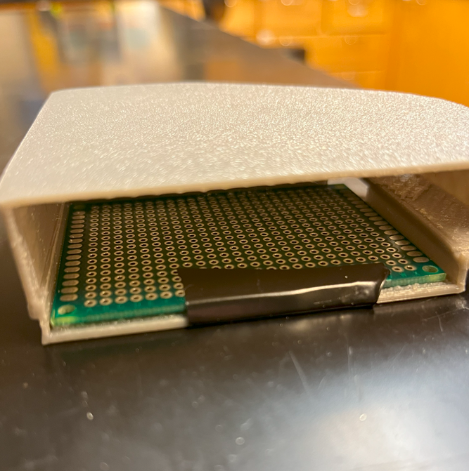
[Figure 10: Insert electronics (perf board used for demonstration)]
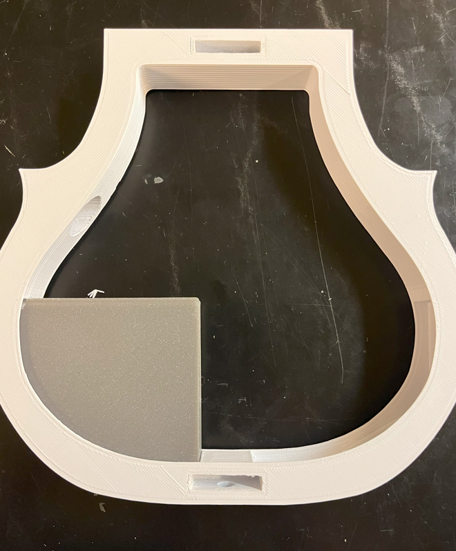
[Figure 11: Insert electronics case into the frame]
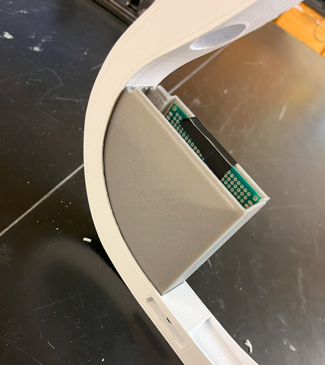
[Figure 12: Inserting the case. Repeat on other side]
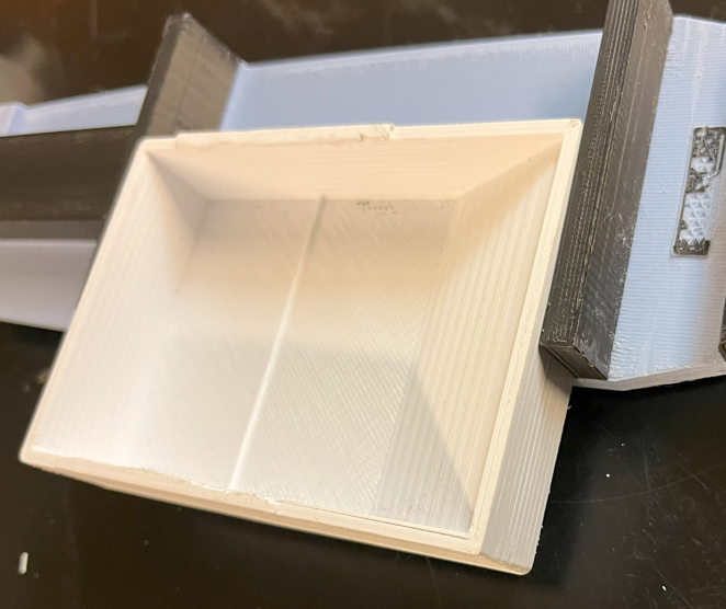
[Figure 13: Insert battery holder into body]
[Figure 13. Line the pegs of the body (blue and black piece) up with the holes in the frame, and push into place (note: battery case missing from image)]
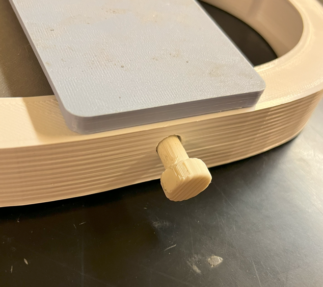
[Figure 14. Insert tailpiece peg into hole in bottom of frame]
[Figure 15. Push the bridge into its slot on the body]
[Figure 16. Insert the pegs on the top frame into the top of the body and the hole in the top right corner of the frame]
[Figure 17. Attach tuning pegs to head; attach to neck]
[Figure 18. Insert neck into the frame]
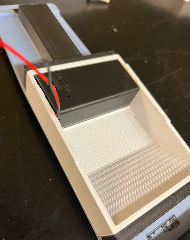
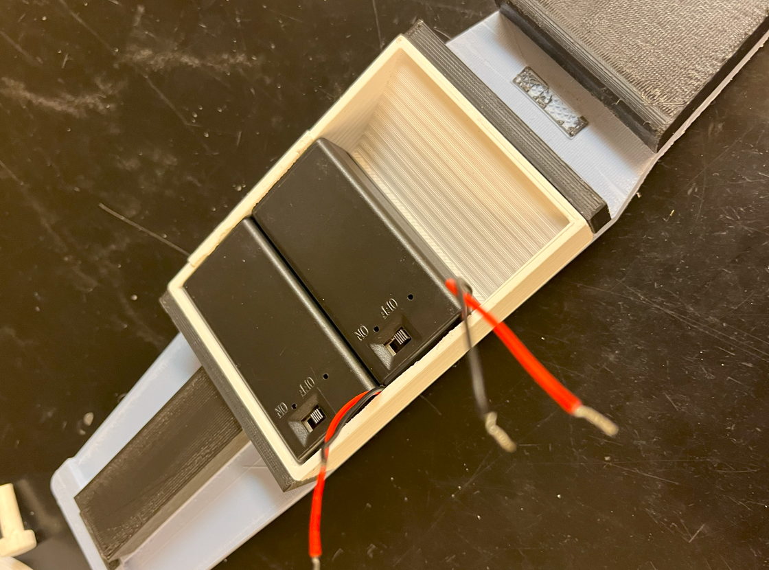
[Figure 19. Finally, slide the two battery cases, with their batteries into the battery holder]
6.2 Pickups
- Solder four piezoelectric discs in series with the audio jack socket as shown in Fig. 3.
- When handling the piezo discs, be delicate and avoid bending them, especially when bending the wire that will wrap around the bridge.
- Glue two piezos to each side of the bridge as close to the top and together as possible without touching, as shown in Fig. 4.
- Additionally, there should be wires leading from the audio jack to the tuner, which is in parallel with the piezos.
6.3 Modular Metronome
These assembly instructions will show the user how to create this device on a breadboard.
- Gather all the tools and components specified in sections 4 and 5 relating to the metronome circuit.
- Program the Arduino Nano with the metronome code.
- Open Arduino IDE with the code shown in Figure 6.
- Connect the computer that has the Arduino IDE open to the Arduino Nano using the USB 2.0 A to Mini B Cable.
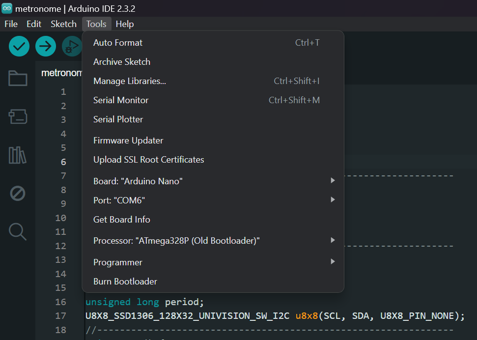
[Figure 20: Arduino IDE Setup]
-
- Go to “Tools” on the toolbar of the Arduino IDE and modify the Board, Port, and Processor to what is shown in the figure above.
- Program the board by pressing the -> button in the upper right corner.
- Once the code properly uploads, unplug the Arduino Nano from the laptop and put the cord away.
- Solder wires to the switch terminals and the terminals of the potentiometer so that it will be able to be wired to the breadboard with ease. Wire length can be variable but 3” wires will allow components to comfortably be connected to the breadboard. The user can always cut it shorter if desired.
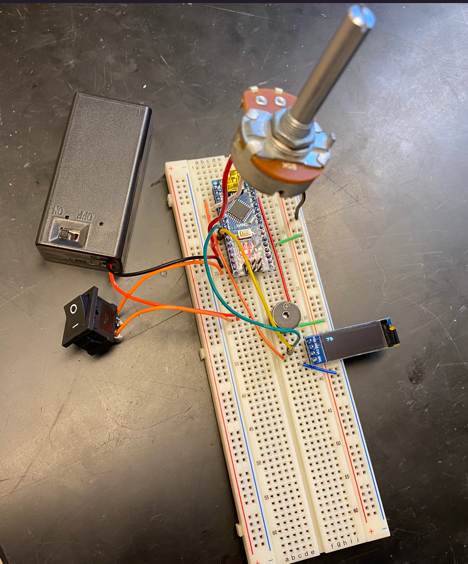
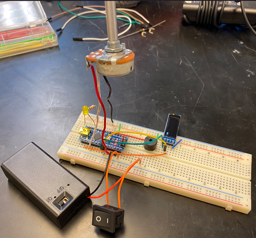
[Figure 21: Metronome Physical Circuit]
- Assembly the breadboard with the components according to the schematic shown in Figure 5. It should look similar to the physical circuit shown in the images above. See the sub-steps below for further help assembling the circuit.
- Put the Arduino Nano on the breadboard first.
- Connect the LED, resistor, and piezo buzzer to the D10 pin on the Arduino. The anode leg of the LED goes to D10 and the resistor connects the cathode of the LED to ground. The piezo buzzer is polarized, so the positive side is connected to D10 and the negative side is connected to ground.
- The Arduino has a GND pin on the same side as D10. Use a wire to connect this pin to ground.
- Connect the OLED display to the breadboard. Use regular or jumper wires to connect the pins to the Arduino. The SDA pin of the display should be connected to A4 of the Arduino. The SCL pin of the display should be connected to A5 of the Arduino. The VCC pin of the display should be connected to 3V3 of the Arduino. The GND pin of the display should be connected to ground.
- Connect the potentiometer to the circuit. Pin 3 goes to the 5V pin on the potentiometer. Pin 2 connects to the A0 pin on the Arduino. Pin 1 goes to ground.
- Lastly, connect the switch and battery to the circuit. The negative terminal of the battery connector goes to the GND pin on the Arduino. The switch wires separate the VIN pin from the positive terminal.
Now that the circuit is assembled, here are some things to note about the user interfaceable items:
- The switch turns the device on and off.
- Turning the potentiometer clockwise increases the tempo up to 200 BPM and turning the potentiometer counterclockwise decreases the tempo down to 60 BPM.
- The buzzer, LED, and display are all indicators of the current tempo being output. None of these can be modified directly, but they will update with the potentiometer.
6.4 Modular Tuner
- Gather the components listed in the tuner BOM, Table 5, and the tools for the tuner, Table 8.
- Assemble the tuner circuit according to the schematic in Fig. 6.
- 3D print the tuner case and lid, and make sure the wires to the batteries, audio jack socket, and OLED display are leading out through the slot in the lid.
- In addition to the schematic, Fig. 22 can be used to help with component placement on a perfboard.
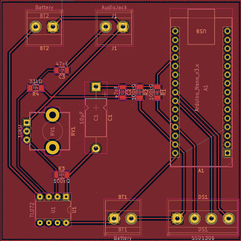
[Figure 22: Tuner PCB]
7. Characterization Data
7.1 Pickups and Tuner
In the following oscilloscope captures, the amplified and offset signal from the tuner circuit can be seen in green, while the raw audio signal is shown in yellow. The audio signal directly from the piezos ranges from about -50mV to 50mV, while the gain from the op amp is adjusted using the potentiometer to get the output of the processed audio signal to less than 5Vpp.
For example, the raw and modified audio signals for when the open A and D strings are bowed are shown in Fig. 23 and Fig. 24.In those figures, it is also apparent that there is a considerable amount of 60Hz noise, which initially caused the tuner to almost exclusively display a reading of approximately 60Hz. The noise by itself when the viola isn’t being played is shown in Fig. 25. When hooked up to an external amplifier, there was no discernable noise that could be heard, so the signal directly from the piezos did not need to be modified. However, the noise was certainly an issue for the amplified signal used to determine the frequency of the audio signal, so the high pass circuit previously discussed in section 3.4 was included in the tuner circuit.
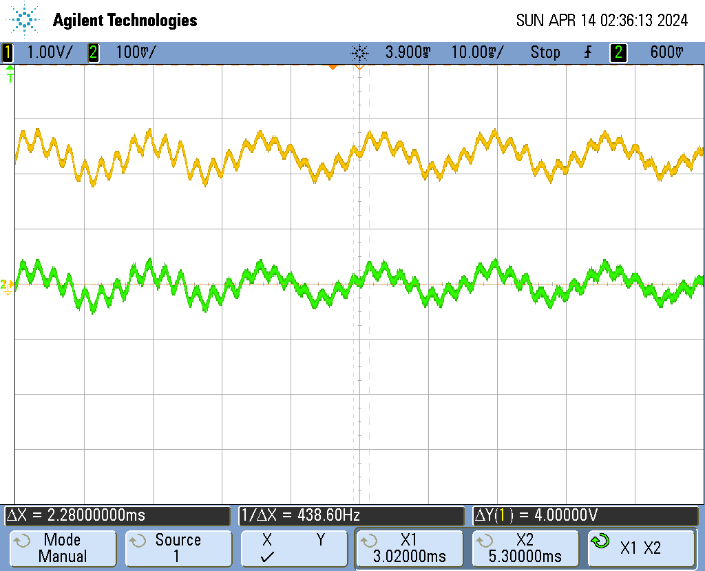
[Figure 23: A String Bowed]
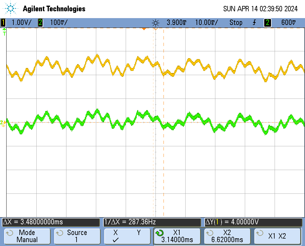
[Figure 24: D String Bowed]
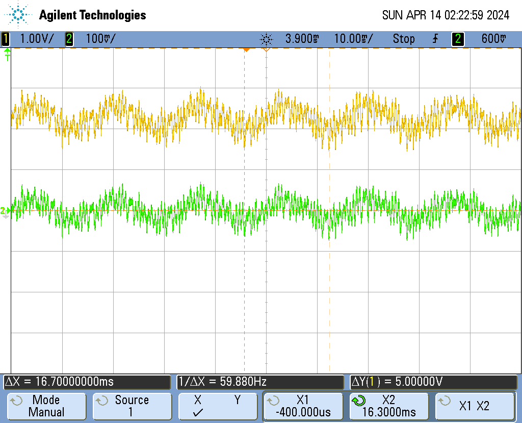
[Figure 25: 60Hz Noise]
It was originally intended for the tuner to be within a minimum of 50 cents of the actual note being played. However, the method of measuring frequency in the time domain caused the readings to only be accurate about half of the time. FFT was explored but not attained, and it would likely be the approach necessary to acquire accuracy and is encouraged for anyone replicating this project.
7.2 Modular Metronome
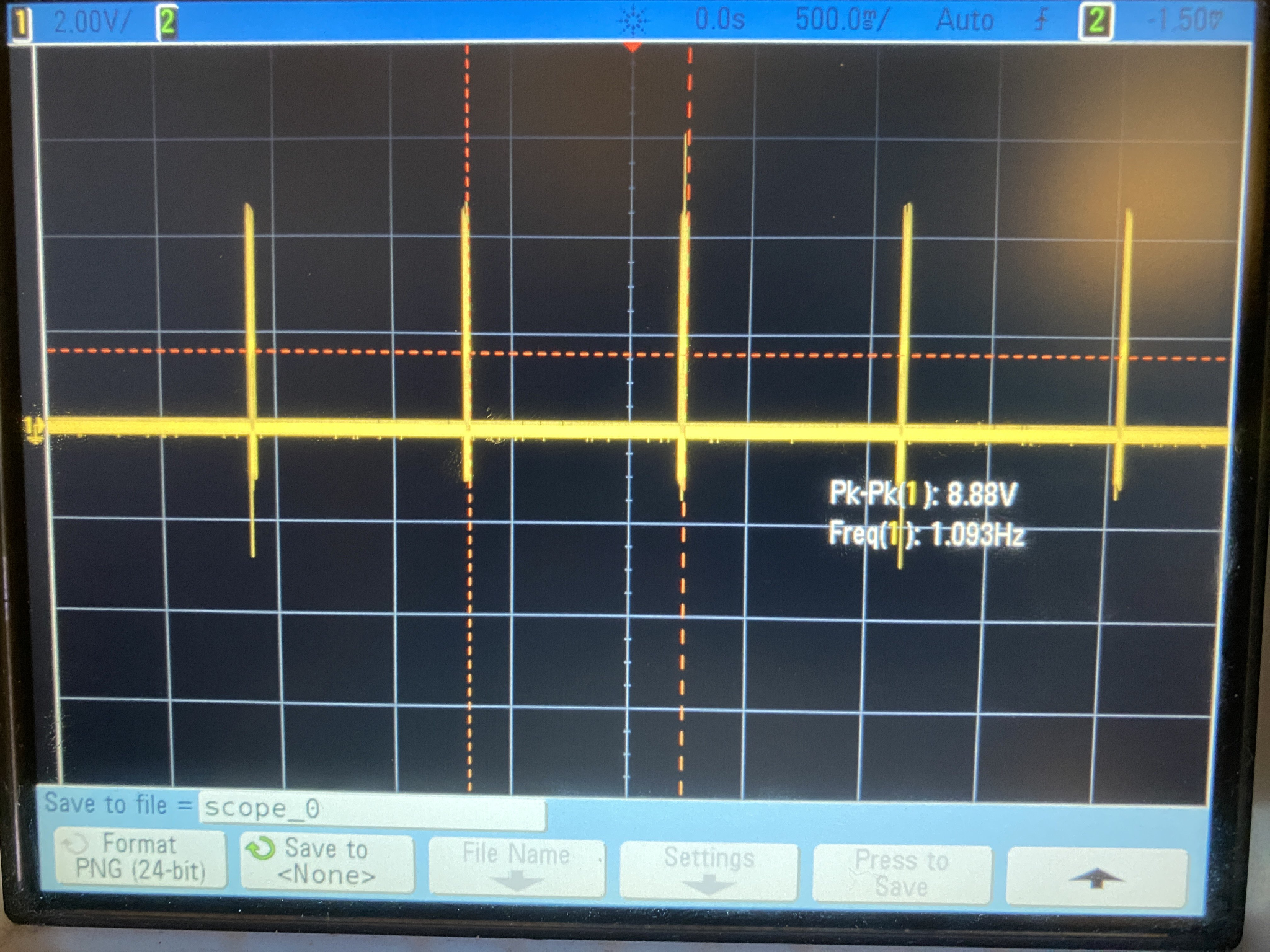
[Figure 26: Oscilloscope Image of Electrical Output 60 BPM]
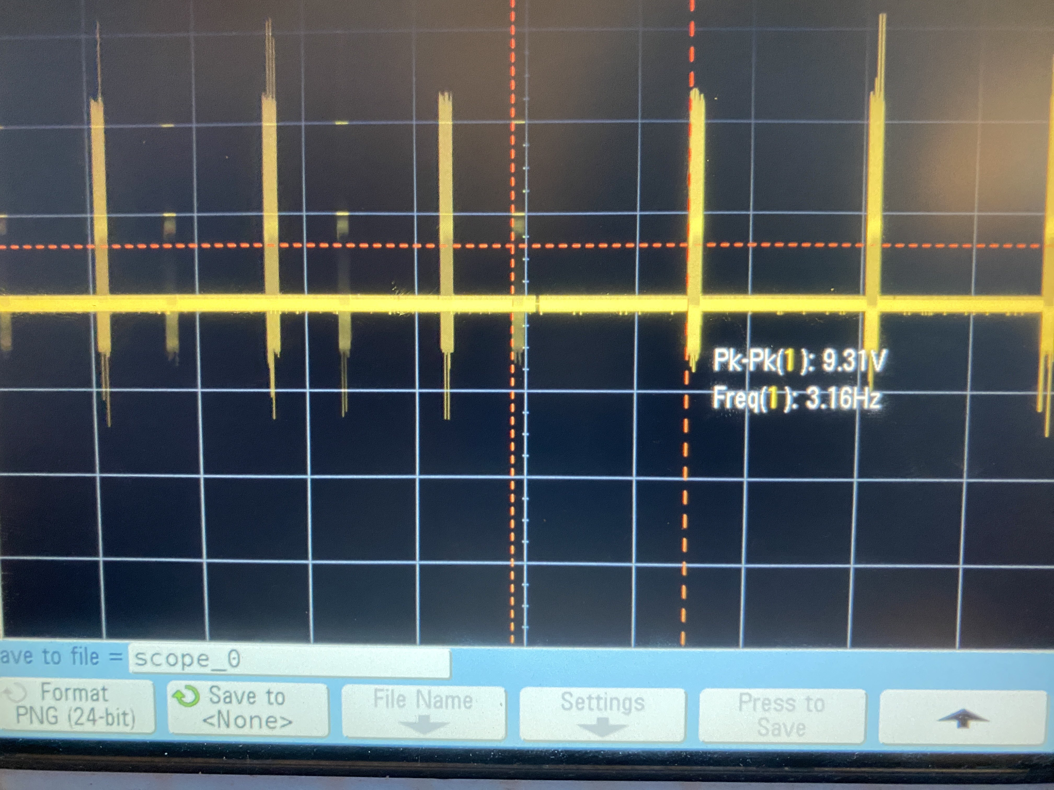
[Figure 27: Oscilloscope Image of Electrical Output 200 BPM]
In order to prove the functionality of the metronome, the accuracy of the tempo it claims to output versus what it actually outputs needed to be tested. This was done by comparing various tempos to a smartphone metronome as well as using an oscilloscope. 60 beats per minute and 200 beats per minute, the lowest and highest tempos the metronome can output, were tested. The frequency was measured and converted to beats per minute to compare to the value the metronome displays. Below are the results:
60 BPM: 1.093Hz → 1.093*60 BPM → 65.58 BPM
200 BPM: 3.14Hz → 3.14*60 BPM → 188.4 BPM
These results show that the metronome is fairly accurate for its simplicity, with percent errors between 6% and 8.3%. Given the cost-effectiveness of this circuit and that it is created for general-purpose use, these numbers are within acceptable thresholds.
8. References
[1] McNeela Music, “Premium Electric Violin,” McNeela Music Store. [Online]. Available: https://mcneelamusic.com/string/violins/premium-electric-violin/. [Accessed: Apr. 6, 2024].
[3] Japan Objects, “Japanese Joinery,” Japan Objects. [Online]. Available: https://japanobjects.com/features/japanese-joinery. [Accessed: Apr. 6, 2024].
[4] Thomastik-Infeld, “What is String Tension?,” Thomastik-Infeld. [Online]. Available: https://www.thomastik-infeld.com/en/stringtelligence/dictionary/what-is-string-tension. [Accessed: Apr. 6, 2024].
[5] Knut’s Acoustics, “Typical String Properties,” Knut’s Acoustics. [Online]. Available: https://knutsacoustics.com/files/Typical-string-properties.pdf. [Accessed: Apr. 6, 2024].
[6] “Material Technical Data Sheet – PLA,” SEAS3D, [Online]. Available: https://www.seas3d.com/MaterialTDS-PLA.pdf. [Accessed: April 13, 2024].
[7] 3D Sourced, “How Strong Are 3D Printed Parts? PLA, ABS, PETG,” 3D Sourced. [Online]. Available: https://www.3dsourced.com/guides/how-strong-are-3d-printed-parts-pla-abs-petg/#pla-filament. [Accessed: Apr. 6, 2024].
[8] Endolith, “Electric Violin”, Endolith. [Online]. Available at: https://www.endolith.com/wordpress/2007/10/13/electric-violin/ [Accessed: Apr. 13, 2024].
[9] Baker, B. “Wiring Diagrams for Piezo Pickup Harnesses”, C. B. Gitty Crafter Supply. [Online]. Available at: https://www.cbgitty.com/news/4-ways-to-electrify-your-cigar-box-guitars-with-piezo-pickup-harnesses-diagrams-included/ [Accessed: Apr. 13, 2024].
[10] Rebres, P. “Make your own arduino metronome”, YouTube. [Online]. Available at: https://www.youtube.com/watch?v=HljWfDTefIQ [Accessed: Apr. 13, 2024].
[11] Rebres, P. “ Metronome”, Dropbox. [Online]. Available at: https://www.dropbox.com/sh/m6c40pu99fqxb5b/AAAe7FpYk6byCTz5a_OlwBxYa/metronome?dl=0&subfolder_nav_tracking=1 [Accessed: Apr. 13, 2024].
[12] Olikraus. “U8glib library for monochrome displays, version 2”, GitHub. [Online]. Available at: https://github.com/olikraus/u8g2 [Accessed: Apr. 13, 2024].
[13] A. Ghassaei, “Arduino Audio Input,” Instructables. [Online]. Available: https://www.instructables.com/Arduino-Audio-Input/. [Accessed: Apr. 6, 2024].
[14] A. Ghassaei, “Arduino Frequency Detection,” Instructables. [Online]. Available: https://www.instructables.com/Arduino-Frequency-Detection/. [Accessed: Apr. 6, 2024].
[15] N. Grimwood, “Arduino Guitar Tuner,” Instructables. [Online]. Available: https://www.instructables.com/Arduino-Guitar-Tuner/. [Accessed: Apr. 6, 2024].