
Growbot Fall 2023 Update
Open Source Hardware Enterprise
December 10, 2023
Eric Engebos (eaengebo@mtu.edu) – Nasi Koukios (adkoukio@mtu.edu) – Nick Kasi (srkasi@mtu.edu)
Background and Vision
This is a project created for the Open Source Hardware Enterprise at Michigan Technological University. A small team of students works on the planning and development of a water resistant remote-controlled robot.
Our project is the Grow-Bot. GrowBot is a proposed device that will be able to assist consumers with creating and maintaining small-scale gardens. The long-term goals of this project are for GrowBot to be able to plant, water, provide health updates, and harvest plants. Grow-Bot is a long term project that has been worked on for many years, with many previous members to reach out to. Also there is a lot of freedom for design and redesign so we can learn new skills and put our own ideas into use.
Functional Requirements:
- (5%) The entire device will have design files that originated entirely from free and open source software.
- (15%) The electronics will be secured
- (5%) The electronics will be organized
- (15%) The robot will have improved accuracy and reliability of gears
- (20%) The robot can be powered on
- (20%) The robot can move forward inside the lab.
- (5%) The robot can turn while moving
- (15%) The robot enclosure has a water resistant cover
New Developments:
This semester we made 3 purchases.
| Part Name | Cost | Quantity | Total |
| FlySky Controller (FS-i6x) and Receiver (FS-iA6B) | 54.99 | 1 | 54.99 |
| Adhesive Foam Rubber Sheet | 12.99 | 1 | 12.99 |
| 5 in. Polyurethane Swivel Caster | 7.99 | 2 | 15.98 |
| Total cost | 83.96 |
FlySky
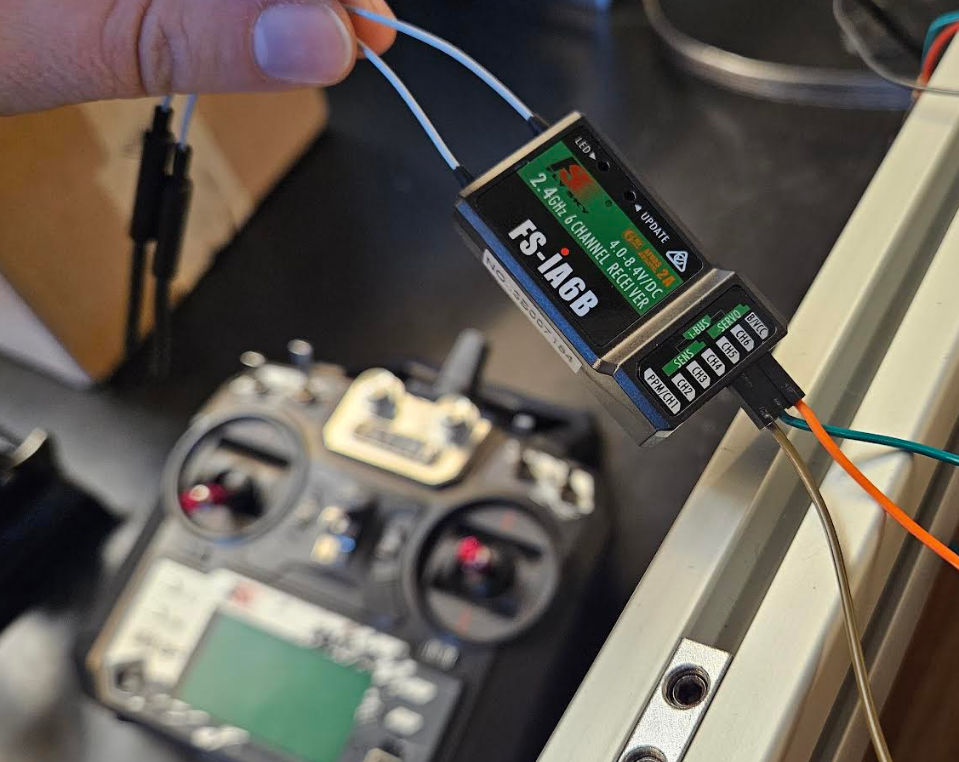
The joystick that was previously used to operate the robot was removed from the breadboard and replaced with a FS-i6x FlySky controller. The FS-iA6B receiver was supplied with power and connected to D19 on the Arduino Mega.
Any FS-iA6B receiver and FS-i6x controller can be paired, they do not have to be purchased together.
- Turn off the controller
- Binding plug must be connected to the B/VCC channel on the receiver.
- Connect a power source to any channel of the receiver.
- A red flashing LED on the receiver indicates the device is in binding mode
- Hold down the binding button on the bottom left of the controller, and power it on.
- Once the LED on the receiver stops flashing, the two devices are bound together, and the binding button on the controller can be released.
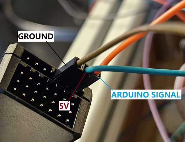
After the receiver and controller are bound, it can be wired to the Arduino Mega. The arduino signal is connected to pin D19, and the receiver needs 5V power and ground. This can be confirmed by checking the Fall 2023 wiring diagram.
Swivel Caster
This semester the back wheels of the robot were replaced with non-powered swivel caster wheels. This allowed for improved maneuverability. The wheel housing mount was changed for the casters to be able to mount to the frame although they didn’t end up getting used for the casters. The casters ended up getting mounted with bolts.
Water resistant Cover
The GrowBot has a new water resistant cover out of plexiglass. It has been cut down to fit the top of the robot’s electronics box. Between the robot and the cover there is a thin layer of foam to keep water from coming under the top cover. The sticky foam was cut in strips to be only along the edges of the top cover.
Replicating the design:
On the Open Source Hardware Enterprise website (https://oshe.io/post/1008/growbot-spring-2023-update/) most of the steps to replicating the Grow-Bot can be found in the Spring 2023 update. Those steps are included below. In addition, we added steps to further the design.
Mechanical:
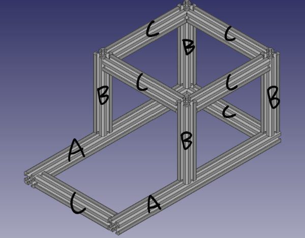
- Assemble chassis
- Cut 30mm T Rails into correct sizes
- A – 2 x 18in
- B – 4 x 8in
- C – 6 x 9in
- Put rails together as shown using 90-degree T slot connectors
- Cut 30mm T Rails into correct sizes
- Print wheel mounts, wheel hubs and actuator gears
- Parts from the OSF Repository (https://osf.io/28dq4/)
- 2 x Front wheel mounts (wheelMount_fall_2023.FCStd)
- 2 x Front wheel mounts (wheelMount_for casters.FCStd
- 2 x Wheel hubs (wheelHub.FCStd)
- 2 x Actuator gears (gears.SCAD)
- Total print time ~50 hours
- Parts from the OSF Repository (https://osf.io/28dq4/)
- Attach bearings to wheel mounts and mount motors
- Attach bearings to both sides of the wheel mounts
- May also require some persuasion
- Mount motors using M4 x 10 screws
- Slide wheel mounts on to T Slot rails and lock in place using T Slot locking hardware
- Attach bearings to both sides of the wheel mounts
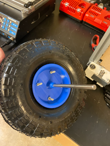
- Replace wheel hubs
- Remove the screws holding the harbor freight wheels together
- Remove just the side with the bearing
- Insert axle rods into printed wheel hubs (May need some persuasion(A hammer))
- Make sure to do this before putting wheel hubs together
- Use M6 screws and nuts to secure printed wheel hub to the remaining original hub
- Add wheels to mounts, add actuator gears
- Slide axle rods through skateboard bearings
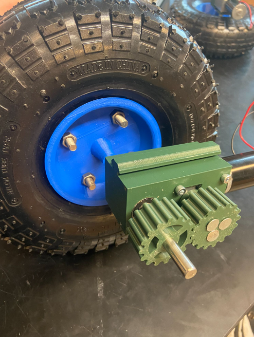
2. Add actuator gears to motor and axle rods
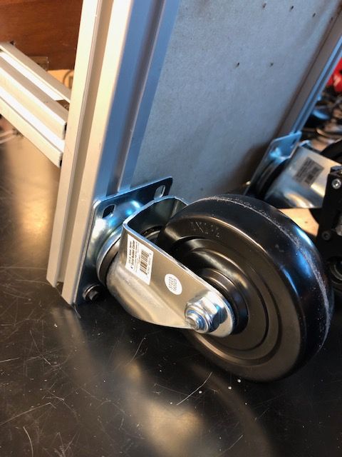
3. Attach 5 inch caster wheels to the back of the robot frame
- Cut a 13 x 13in plexiglass cover to use as a water resistant cover for the electrical box
- Cut the adhesive foam to run along the edges of the electrical box to help keep water from running underneath the plexiglass cover
- Attach the new water resistant cover with L-Brackets
Electrical:
A wiring diagram was created with the open-source software KiCad (https://www.kicad.org/). A PDF as well as the modifiable KiCad file can be found on the OSF repository (https://osf.io/28dq4/).
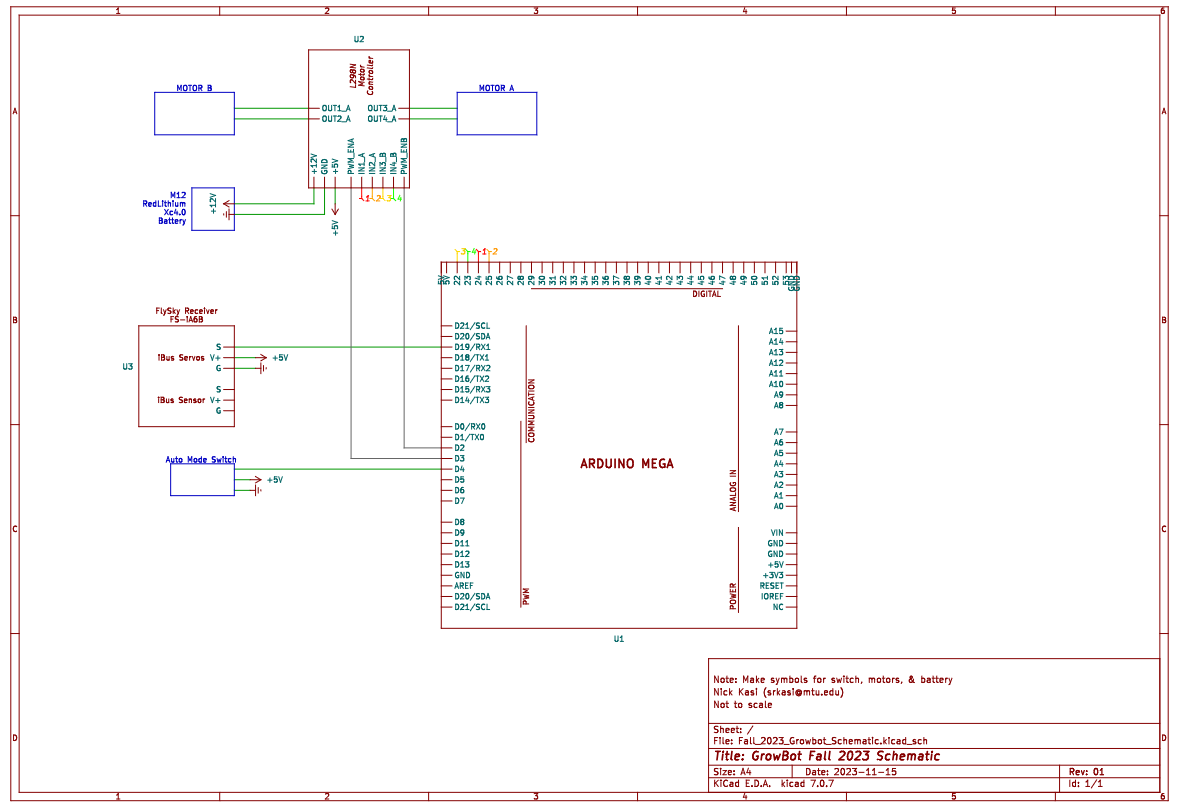
The Fall 2023 Growbot schematic includes the following components:
- Arduino Mega
- L298N Motor Controller
- FS IA6B Flysky Receiver
- 2x Motors
- 2x Switch
The schematic details locations of pins and connections. In practice, the Arduino Mega powers the lines on a breadboard with 5V and ground for easier distribution.
Motor Control:
The Growbot is driven by two 12V 634JSX‑31ZY motors with gearboxes on the front wheels. These motors are supplied power from the battery using the L298n motor controller. This controller also supplies 5V of power to the Arduino Mega.
This semester, the code was updated to be operated with a FlySky controller instead of a joystick. The Growbot code is a modified version of an RC arduino car in the following link (https://dronebotworkshop.com/radio-control-arduino-car/). It can be found in the OSF repository (https://osf.io/mb9rh).
Notes for code:
- Many sensors are not connected to the Growbot. The code contains functions for the operation of the Humidity Sensor and SD card, though they have not been tested.
- In addition, auto mode is not operational. Though it can be enabled with the switch on the Growbot, the ultrasonic sensor has not been tested.
- The “default case” for the FlySky receiver was a large roadblock for the team. Currently, when the FlySky controller is disconnected either (ex. being out of range), the receiver will continue outputting the last signal it received. So, if the last signal was not to move the motors, it will stay still. However, if the last signal was to drive forward, the robot will continue driving even without controller input.
Code can be deployed to the Arduino Mega using the Arduino IDE (https://www.arduino.cc/en/software). When the Arduino Mega is plugged into the device, running the serial monitor displays information about the signal seen by the receiver. In the Main Loop of the code, this is represented by the Serial.print functions corresponding to the direction of RC control. If the main loop for RC mode does not contain disable = 0, the wheels will not spin. The baud in the code must be the correct value. In the current version of the code, it is 9600: Serial.begin(9600). If this is not correctly configured, the serial monitor does not display symbols correctly.
The code does not use PWM motor speed control. On the motor controller, speed has been set to full power with jumpers to 5V power.
Software:
| Tool | Link |
| Motor Control with RC Controller | https://dronebotworkshop.com/radio-control-arduino-car/ |
| KiCad | https://www.kicad.org/ |
| FreeCad | https://www.freecad.org/ |
| Arduino IDE | https://www.arduino.cc/en/software |
Hardware:
| Part | Link | Price | Quantity | Total |
| 30 x 30 mm T Slot Rails | Amazon.com | $25.00 | 2 | $50 |
| 10 in Pneumatic tires x 2 | harborfreight.com | $8.49 | 2 | $16.98 |
| 5 in Caster Wheels | In store Harbor Freight | $8.99 | 2 | $17.98 |
| Arduino Mega | Arduino.cc | $41.14 | 1 | $41.14 |
| L298N Motor Drive Controller 4pcs | https://tinyurl.com/56w9rc46 | $11.49 | 1 | $11.49 |
| Axle Rods | Amazon.com | $8.99 | 1 | $8.99 |
| 8mm Skateboard Bearings | Amazon.com | $9.59 | 1 | $9.59 |
| FLYSKY RC Transmitter Controller | Amazon.com | $52.99 | 1 | $52.99 |
| 8mm Linear Rail Stop Collars | https://a.co/d/4P2c1dW | $13 | 1 | $13 |
| Milwaukee 12V Battery Adapter | https://a.co/d/a3XeQW0 | $13 | 1 | $13 |
| 634JSX‑31ZY Motor and Gearbox | https://www.aliexpress.com/i/2251832136653723.html?gatewayAdapt=4itemAdapt | $32.29 | 2 | $64.58 |
Required Arduino Libraries:
SPI.h https://github.com/PaulStoffregen/SPI
SD.h https://github.com/arduino-libraries/SD
DHT.h https://github.com/adafruit/DHT-sensor-library
HCSR04.h (2.0.0) https://www.arduinolibraries.info/libraries/hcsr04
TinyGPS++ TinyGPSPlus – Arduino Reference
Future Plans:
For next semester, our plans are to replace the wooden components of the Growbot with a waterproof material, as well as implement a more secure form of power distribution with available space to add other components such as motors for end effectors later. In addition, wires will be labeled for further clarity when disconnecting and reconnecting components.