
Project Description and Incentive
OSF: https://osf.io/dj6gz/wiki/home/
All code and design files located on OSF repository
The Bird Attractant and Deterrent device (BAD) aims to guide birds away from cities as they migrate south for the winter. Building collisions are the second leading cause of bird death, resulting in the death of over a billion birds a year. The BAD uses different sounds to attempt to, in a sense, shepherd birds away from potential hazards in the migratory path. By outputting sounds at a frequency at which birds commonly communicate, the birds may become annoyed and move to a different area to get away from the noise. A similar effect is planned to be created using predatory sounds. The BAD was created for researchers in the forestry department of Michigan Technological University. The researchers will use the BAD over the summer of 2023 to determine if the sounds output by the device have any effect on the migration of the birds. If there is a proven effect, the theory behind BAD may be incorporated into major cities and potentially save millions of birds annually.
Goals and Progress
Mechanical Assembly
In the V2 version the method of installation has now changed. Since the box is being set in a typical environment mounted to poles with wall outlet a different power system is opted out which is discussed more in the electrical section.
Since wall power is being used a power cable now leaves the box into a duplex that is mounted into the box. A pg connector is used to ensure that no water enters the box. To note. A pg connector was also used for the output of the speakers. The speaker cable also has a waterproof DTP connector so the speakers can be disconnected and changed with ease. Most of everything is mounted onto the box by drilling holes for m4 screws and epoxied over to ensure waterproofing. On the back of the box general pole mounting hardware is installed to equip it to a pole. The Speakers are mounted on the sides.
Inside with the duplex can be found the amp, the pi and interface module consisting of the screen and the keypad. The pi is held down using velcro tape and sat beneath the interface module. The amp and interface module both have 3d printed parts which can be found in the files section. The interface module has both the screen and keypad which are both attached with m4 screws. The 3d print is then attached to the box with more mounting screws. The amp mount is at and angle so ensure that people can still interact with the amp without having to deal with weird angles. This is also helped with the addition of stand offs to ensure that. There is a file with the amp stand, the standoffs and both of them combined.
Electrical Assembly
The primary change to V2 is the power delivery. The sponsors mentioned they would be installing several units in a city, and a grid connected model would be ideal. This has several advantages, mainly complexity and weight. Removing the battery and solar controller enabled us to shrink the design to a much smaller footprint. This allowed us to design this model specifically for pole mounting scenarios, and everything is integrated into one enclosure. Power delivery is handled by 120VAC into the enclosure into a duplex outlet, where all the other peripherals are connected. Power consumption is still low, however with grid connectivity this is no longer the chief concern. PG connectors are utilized as bulkheads through the enclosure for both speaker cables and the power cable.
Outside of power delivery differences, considerable improvements were made to the controller and the amplifier. These changes can easily be retroactively implemented into V1 and in all practicality is a superior solution. The controller was changed from the ATmega2560 to the Raspberry Pi Model 3B+. This new controller has orders of magnitude more processing power, other advantages such as native audio output, a clock module, internet connectivity, usb connectivity, a display output, and runs Linux natively. Since the design of V1, prices came down considerably for Rasberry Pis enabling the use of this hardware for V2. The interface, for V1 was a rotary encoder, in practice it was unreliable, imprecise, and it was difficult to input values with it. The decision was made to transition to a 12 button keypad. The keypad could be used for up/dn rght/lft and enter navigation, as well as numeric entry using the keys. This proved to be an enormous improvement and enabled much more complicated interactions with the machine. The display was upgraded from a 16×2 LCD to a 20×4 LCD facilitating these complex menu interactions, and allowing more information to be displayed and read form the machine.
Another change was the handling of audio. The transition to an off the shelf component for the amplifier, and the native stereo audio outputs from the Raspberry pi facilitated this improvement. Aside from the quality improvement, the external amplifier enabled easy adjustments such as volume bass and treble. The raspberry pi, is also capable of handling stereo .mp3 files without and complicated conversion as was required in V1. Any bitrate is acceptable, this is much more user friendly and combined with the easy to adjust volume controls made this a large quality of life improvement.
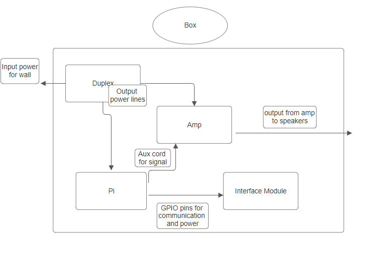
A block diagram and schematic are located in OSF files for high level connections. Connections between GPIO components were made using female-female header pins.
The pinout is located below for RPi GPIO pins along side a block diagram for the box.
| Pin | Value | Connected | Pin | Value | Connected |
|---|---|---|---|---|---|
| 1 | 3V3 | – | 2 | 5V | – |
| 3 | GPIO2 | – | 4 | 5V | – |
| 5 | GPIO3 | – | 6 | GND | – |
| 7 | GPIO4 | – | 8 | GPIO14 | – |
| 9 | GND | – | 10 | GPIO15 | – |
| 11 | GPIO17 | – | 12 | GPIO18 | – |
| 13 | GPIO27 | – | 14 | GND | – |
| 15 | GPIO22 | – | 16 | GPIO23 | – |
| 17 | 3V3 | – | 18 | GPIO24 | – |
| 19 | GPIO10 | – | 20 | GND | – |
| 21 | GPIO9 | – | 22 | GPIO25 | – |
| 23 | GPIO11 | – | 24 | GPIO8 | – |
| 25 | GND | – | 26 | GPIO7 | – |
| 27 | GPIO0 | – | 28 | GPIO1 | – |
| 29 | GPIO5 | – | 30 | GND | – |
| 31 | GPIO6 | – | 32 | GPIO12 | – |
| 33 | GPIO19 | – | 34 | GND | – |
| 35 | GPIO19 | – | 36 | GPIO16 | – |
| 37 | GPIO26 | – | 38 | GPIO20 | – |
| 39 | GND | – | 40 | GPIO21 | – |
Code and Integration
Replacing the Arduino Mega with the raspberry Pi it possible to use python rather than just Arduino C++. The Pi also gave us significantly more computing power than the Arduino.
The code has essentially gone through a complete rework when compared to the previous semester. While the flow of the code is very similar, the reworked python code is more compact and proves to be significantly more effective. By having less lines of code, errors were easier to track down and correct.
Several python libraries were imported the project. The following libraries were all installed using pip: pygame, adafruit_matrixkeypad, and mutagen.mp3. A LCD library was used to control outputs to the LCD display. The I2C device configurations were set by following a tutorial created by Scott Cambell. Pygame was used mainly for audio playback. Pygame makes it easy to start and stop sounds. Mutagen makes it possible to get descriptions of certain characteristics of mp3 files. Mutagen was used in the project to figure sampling rates of the mp3 files which were used to make the output of the audio play at the right speed. The matrixkeypad was used to easily interface with the keypad. The library takes care of some of the computation involved with reading from the keypad.
Use Instructions
- Plug the device in to a wall outlet.
- One plugged in, the device needs some time to start up. Wait for the LCD to display the main menu.
- The device uses the numeric key pad for navigation as well as input. Key 2 is used to move the cursor up and key 8 is used to move the cursor down. Key 5 is used to make selection.
- After startup, the device time should be set. This can be down by moving to the time menu and selecting device time. After selecting device time, input the current time in military time.
- While in the time menu, the time at which the user would like audio to be played can also be set. This time can be set by selecting alarm time and inputing the desired time in military time.
- After setting the times, the desired audio file can be selected. This can be done in the sound menu. Select the File option. An X should replace the cursor indicating that a file is being selected. The current audio files on the device can navigated through using the 4 and 6 keys. To select a file, press the 5 key.
- The audio can be tested by selecting test audio. This will play a test file that is on the device.
- After setting the time and selecting a file, the device is ready to play audio and will start when the device time is equal to the alarm time.
To upload audio files: Files can be uploaded to the device via wifi or USB. The raspberry pi will need to be removed and controlled via mouse and keyboard. The files need to be placed into the home directory and must be mp3 files. As long as the file is mp3 it should work fine, no further changes need to be made to the files.
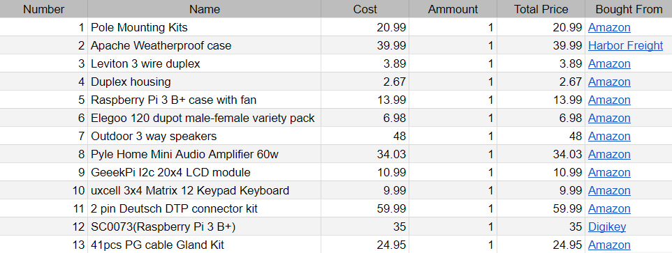
Bill of Materials
strict cost requirements to ensure that the project’s specifications were met without exceeding the budget. To achieve this goal, the team documented every item purchased in the bill of materials, including the quantity, source, cost, and notes about each product.
Links and Resources