
Stephen Metcalfe
Adam Sandahl
Nick Sandahl
Liam Cacioppo
Derek Gottwalt
GrowBot is a proposed device that will be able to assist consumers with creating and maintaining small-scale gardens. The long-term goals of this project are for GrowBot to be able to plant, water, provide health updates, and harvest plants. The reason we chose this project is that we wanted to have access to fresh, homegrown produce, even if you are a busy professional.
Functional Requirements:
- Drive GrowBot manually
- This goal is to get growbot driving with the use of a joystick. Currently, growbot drives with a RC controller.
- Drive GrowBot autonomously
- This goal is to give growbot some forms of inputs other than a controller. Currently, growbot was given an ultrasonic sensor that detects if an object is in front of it. It’ll drive forward until it sees something and then will turn left.
- Read and store meaningful data from a relevant sensor to monitor garden
- This goal is to give growbot sensors to monitor the garden and a way to store the information. Currently, Growbot has temperature and humidity sensors. The readings from these sensors are stored onto a micro sd card.
- Create an accessible and water resistant electronics casing
- This goal was to create a location to store growbot’s electronics. Currently, a wooden and plexiglass enclosure is at an elevated location on growbot. The enclosure holds the arduino, motor controller, and a variety of other electronics. The enclosure is antiquity water resistant. WE were able to pour water on the top and not destroy the electronics. It is only water resistant, not proof. Growbot can not swim.
- Complete local positioning system
- The location position system currently has been replaced with a gps module.
- Continue plant classification to monitor garden health
- A new image detection model was trained to recognize ripe and unripe tomatoes. This model was then implemented on a Raspberry Pi with a Raspberry Pi camera for live image detection.
- Continue web interface system
- The web interface was not worked on.
- Use only open source software and tools
Value-Added Goals:
- Determine basic method of charging GrowBot
- Growbot is now powered using Milwaukee M12 batteries. This allows for easy recharge by using milwaukee battery chargers. The battery system can be replaced by any other power tool battery if a voltage drop is added so that the input voltage to growbot is 12v.
- More in-depth documentation
- Create a standard ROS Image
- Alternative tank tracks
- Tank tracks were not created for growbot due to the time requirements needed to create our planned 3d printed tracks. Future attempts at tracks should find a more suitable production of tracks than 3d printing.
- Create a wireless controller to control GrowBot manually
- Growbot is currently controlled with an rc controller. The current controller doesn’t belong to growbot and will need a replacement. A flysky or other configurable 2.4gHz controller would be suitable.
Steps to Replicate:
Mechanical:
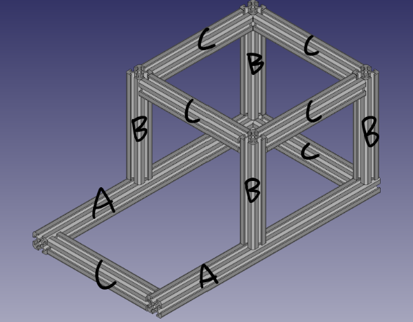
- Assemble chassis
- Cut 30mm T Rails into correct sizes
- A – 2 x 18in
- B – 4 x 8in
- C – 6 x 9in
- Put rails together as shown using 90-degree T slot connectors
- Cut 30mm T Rails into correct sizes
- Print wheel mounts, wheel hubs and actuator gears
- Parts can be downloaded from the GitHub repository
- 4 x Wheel mounts (wheelMount_2.3.FCStd)
- 4 x Wheel hubs (wheelHub.FCStd)
- 4 x Actuator gears (gears.SCAD)
- Total print time ~50 hours
- Parts can be downloaded from the GitHub repository
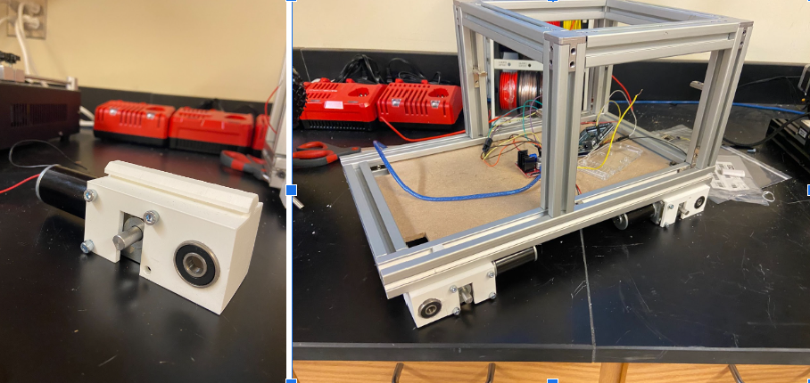
- Attach bearings to wheel mounts and mount motors
- Attach bearings to both sides of the wheel mounts
- May also require some persuasion
- Mount motors using M4 x 10 screws
- Slide wheel mounts on to T Slot rails and lock in place using T Slot locking hardware
- Attach bearings to both sides of the wheel mounts
- Replace wheel hubs
- Remove the screws holding the harbor freight wheels together
- Remove just the side with the bearing
- Insert axle rods into printed wheel hubs (May need some persuasion(A hammer))
- Make sure to do this before putting wheel hubs together
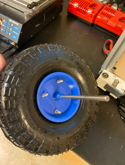
D. Use M6 screws and nuts to secure printed wheel hub to the remaining original hub
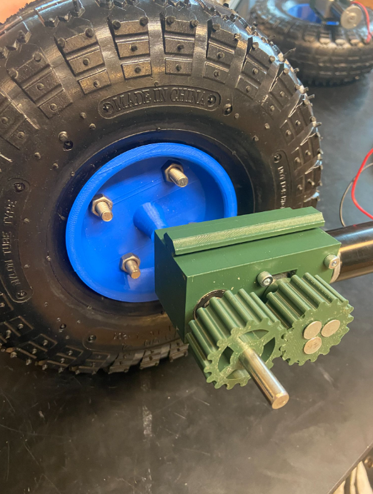
- Add wheels to mounts, add actuator gears
- Slide axle rods through skateboard bearings
- Add actuator gears to motor and axle rods
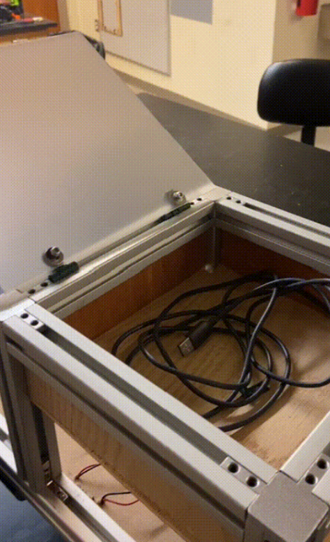
Electronics Enclosure:
The enclosure was constructed out of wood panels and a sheet of plexiglass. This box is added at the top location of growbot. The panels are held within the grooves of the extruded aluminum frame and the plexiglass is hinged on the top to allow for easy access to the electronics.
Ultrasonic Sensor Mount:
A mount was made to hold the ultrasonic sensor on the front of the bot. This part is 3d printed and mounted to the extruded aluminum slots.
Electrical:
Motor Control:
Growbot’s 12v motors are driven using the L298n motor controller.. The tutorial for using a flysky rc controller (https://dronebotworkshop.com/radio-control-arduino-car/) was used to create the majority of the code. The rc car sketch was modified to use a non flysky controller and spin mode replaced with an autonomous driving mode. The motor speed of the controller was set to always full power with jumpers to the 5v power. This removed the need for the PWM motor speed control, so those pin assignments were removed. The replacement of the flysky controller code made use of the PWM input code shown earlier on the tutorial. This used three pins to connect to the receivers channels 1, 2, and 5. To remove all the flysky controller code all forms of iBus library were removed. This includes the serial connection and the methods for reading channels. The last major modification was the logic to stop moving. This was done with a flag “disable” that when set to 1 will set all direction control pins to low so that the motors stop.
Sensors and Data collection:
Growbot’s arduino board uses 2 sensors to gather data and autonomously drive. It has DHT11 Temperature and Humidity Sensor to log both temperature and humidity in a text file on the SD card from the SD card reader. This is done using the tutorial by IOTDesign Pro (https://iotdesignpro.com/projects/logging-temperature-and-humidity-data-on-sd-card-using-arduino ). This tutorial uses 3 libraries to read values from the data pin on the DHT11 sensor and to read and write onto a sd card. Growbot uses an Arduino Mega board instead of the Arduino Uno board, so the MISO, MOSI, and SCK are located at pins 50, 51, and 52 instead of pins 12, 11, and 13. The next sensor Growbot uses is an ultrasonic sensor (HC-SR04). This sensor is positioned on the front of the frame of the bot to detect objects impeding its path. The sensor uses two data pins and the HCSR04.h arduino library by Martin Sosic to find the distance forward from the sensor to an object. The two pins are Trig and Echo. Trig sends out a soundwave and Echo reads when that wave returns. Using the Trig pin as an output and Echo pin as an input, an UltraSonicDistanceSensor Object can be made and have the measureDistanceCm() method called for said sensor to output the distance read by the sensor. The sensor on Growbot continuously checks for objects in front of it while in autonomous mode. When an object is detected within a set range, the bot stops moving forward and turns left until no object is detected. A note for continuing the project is to add another ultrasonic sensor and have the two sensors on outward angles to provide a larger range of detection for more accurate detection and better responses. An overview of the ultrasonic sensor can be found here (https://howtomechatronics.com/tutorials/arduino/ultrasonic-sensor-hc-sr04/ )
Software:
Image Classification:
To set up your Raspberry Pi, first download Raspberry Pi Imager and download a usable image. It is important to note that the Raspberry Pi camera module is only supported on 32-bit OS. For this project I used the latest version of Raspberry Pi OS. Follow the initial menus to configure your Raspberry Pi, including a wifi connection and your desired location, username, and password. Be sure to connect your Raspberry Pi camera by connecting the ribbon cable to the correct port. To use the camera you may have to run raspi-config in the command line and enable legacy camera support. If you plan to connect to your Pi using SSH or VLC be sure to enable these as well.
Once all of the hardware is setup, follow this tutorial to install the image detection python script. To run it make sure to source the virtual environment by typing source ~/tflite/bin/activate in the command line. Then move to the appropriate directory cd examples/lite/examples/object_detection/raspberry_pi and run the python script python3 detect.py. This will run a pre-trained TensorFlow Lite model which has some common objects, but does not detect tomatoes.
To train your own model to detect plants, follow the steps in this Google Colab. This details how to train a model for ripe and unripe tomatoes in which the data can be interchanged to detect any class of objects. If the Google Colab is down, the source Jupyter Notebook is available in the OSF repository. Also available in the OSF repository is a pre-trained tomato detecting model which can be downloaded on the Raspberry Pi and deployed. Once the desired model is downloaded on the Raspberry Pi, follow the same steps to run the detect.py script but this time run with the –model flag as follows python3 detect.py –model <name of model>.tflite. A window will appear which will display the camera feed, and bounding boxes will be placed on the detected images along with an object class and confidence interval.
Localization:
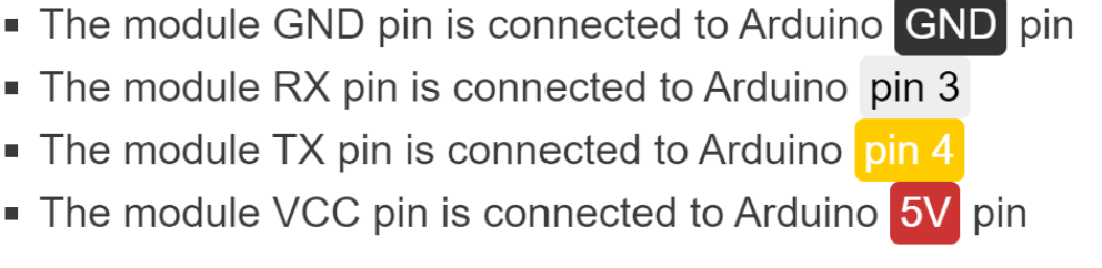
GrowBot localizes itself using a Hi-Letgo GY-NEO6MV2 flight controller GPS module. Testing is still ongoing to fully integrate localization. For now, local home positions can be set and GrowBot will stay within the boundaries. A link to the GPS module is provided below, as well as the library needed to use it. A wiring diagram is shown immediately below:
| Tool | Link |
| Raspberry Pi Imager | https://www.raspberrypi.com/software/ |
| Kaggle | https://www.kaggle.com/datasets/andrewmvd/tomato-detection |
| Zenodo | https://zenodo.org/record/5596799#.ZEnRSHbMK3C |
| TensorFlow Lite Model Maker | https://www.tensorflow.org/lite/guide/model_maker |
| Google Colab (Jupyter Notebook) | https://colab.research.google.com/drive/1uEN3dSeH0wYoKXP9JFkh_lzGYURb9Fkf https://docs.jupyter.org/en/latest/ |
| Motor Control with RC Controller | https://dronebotworkshop.com/radio-control-arduino-car/ |
| Humidity Sensor and SD Card Reader | https://iotdesignpro.com/projects/logging-temperature-and-humidity-data-on-sd-card-using-arduino |
| Ultrasonic Sensor | https://howtomechatronics.com/tutorials/arduino/ultrasonic-sensor-hc-sr04/ |
OSF Link: https://osf.io/sczuj/
GitHub Link: https://github.com/OSHE-Github/GrowBot
Required Arduino Libraries:
SPI.h https://github.com/PaulStoffregen/SPI
SD.h https://github.com/arduino-libraries/SD
DHT.h https://github.com/adafruit/DHT-sensor-library
HCSR04.h (2.0.0) https://www.arduinolibraries.info/libraries/hcsr04
TinyGPS++ TinyGPSPlus – Arduino Reference