

Prepared by: Cory Muehlmeier, Ben Boelens, and Evan Jablinskey
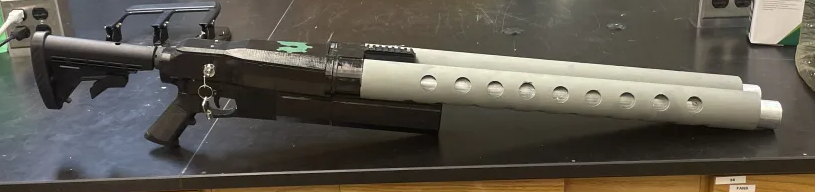
1. Main Product Image
2. Project Description
In the past semester, SHARK Laser Tag has been working on trying to implement the Ideas that we thought of last semester. This was to improve the first and second versions of the shell, start testing the software, and finish out the PCBs to have everything in a hopefully working state. With this semester progress has been going very well although there was some turbulence. At the end of the day we hopefully will provide an updated and fully integratable system to interact with the MILES Tag 2 system.
3. Methodology in Brief
3.1 Blaster Shell
Summary of Research:
- What size and shape needed to fit desired parts
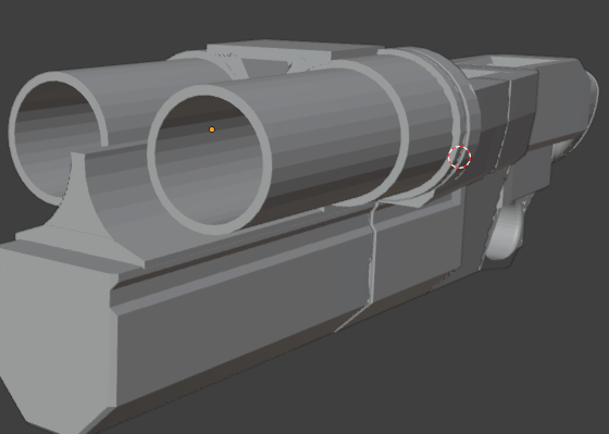
- We chose to go for a two barreled design with space to store the electronics and the headset
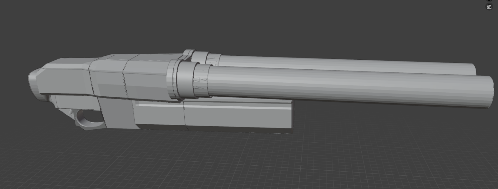
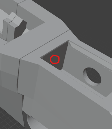
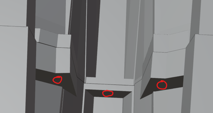
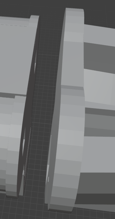
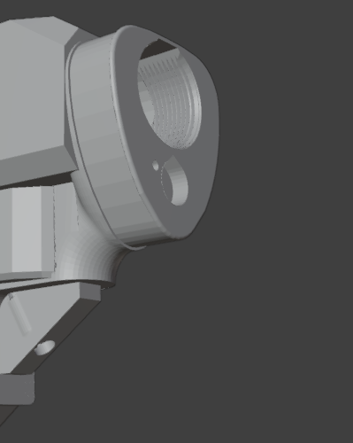
MK 3 3D model
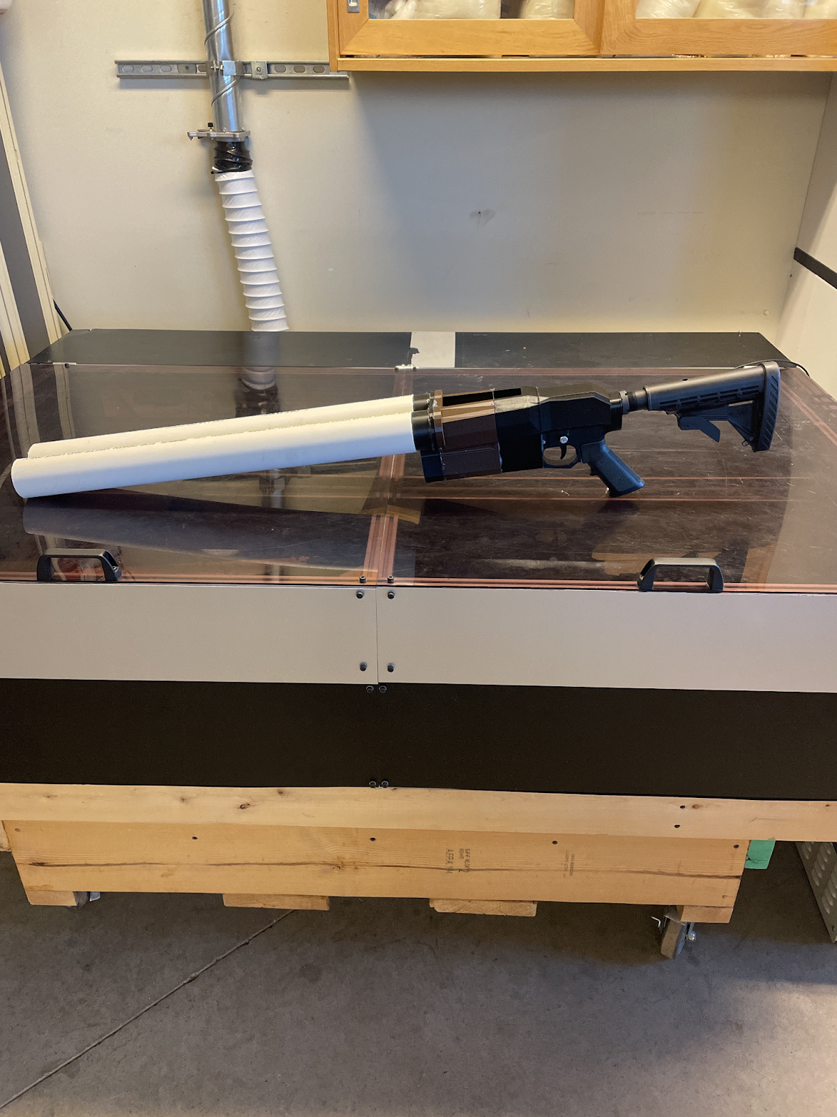
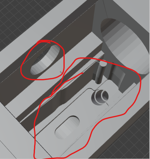
MK 1
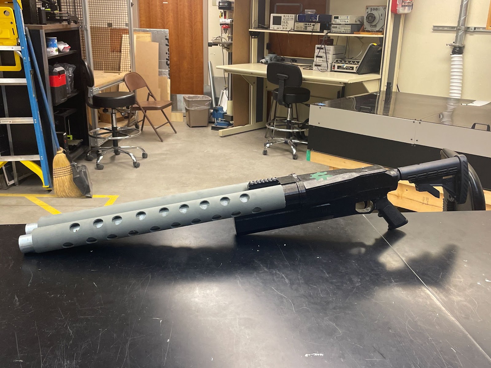
Final Mk 3 version
- For the shell it’s mostly made out of 3d printed materials about 1kg or one spool 20$
- The other parts to note are the barrel shrouds made out of two pvc pipes 10$ and two metal pipes 50$ and a 30$ ar-15 butstock and buffer tube
- The most important tool needed for this part of the project was access to a 3d printer and basic tools like bolts and assorted sized drill bits and drill
3.2 Teensy
A teensy was chosen over other microcontrollers due both to its ease of development and its speed. Because it uses the arduino IDE and arduino libraries, it allows for easy modification and implementation for both our initial implementation and for future groups who may want to build off of our work in the future. We chose a teensy over an arduino due to the speed of the processor. The protocol requires precision in the triggering of the IR LED above and beyond the ability of a standard arduino to fulfill. Because a teensy is faster, it is able to fulfill the requirements of the protocol.
3.3 Auxiliary Board
Summary of Research
- Needed to be smaller or the same size as the previous board
- Needed to fill as a voltage regulator for the new microcontroller
- Found parts that fit the specs and were easily available
- Used updated parts for other external components that the Teensy is set to control
- Testing may require additional modifications to the board
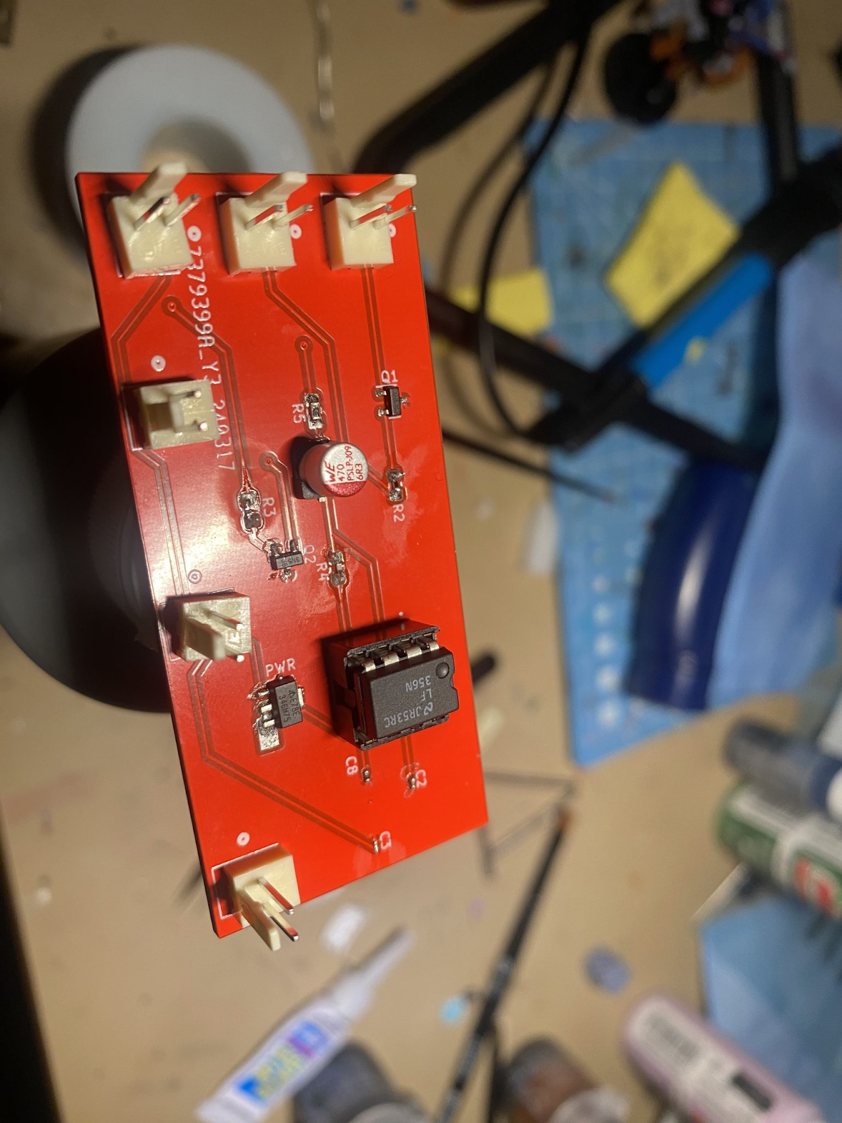
First Iteration of Auxiliary Board
4. Bill of Materials (BOM)
4.1 Blaster Shell
| Part Name | Quantity | Infill | Approx. Print Time |
| Main body | 1 | 5% | 1.2 days |
| Forward body | 1 | 5% | 19 hr |
| Forend | 1 | 5% | 12 hr |
| Sights and laches | 1 | 10% | 5hr |
| Grip | 1 | 5% | 19hr |
| Part Name | Quantity | Price | |
| PVC | 2 | 10$ | |
| Metal tubes | 2 | 50$ | |
| Bolts & nuts | 5 | 2$ | |
| Ar 15 stock & tube | 1 | 30$ | |
| Key latch | 1 | 15$ | |
| Epoxy | 1 | 10$ | |
| Sight Rail | 1 | 12$ |
4.2 Teensy 4.0
4.3 Auxiliary Board
5 PCBs off of JLCPCB ~$20 with shipping
| Item | Part Number on Digikey | Qty |
| LMN386N-1 | LM386N-1-ND | 1 |
| TE Connectivity OP-AMP Socket | A120347-ND | 1 |
| DMN3051L | DMN3051LDITR-ND | 2 |
| AS78L05RTR-E1 | AS78L05RTR-E1DITR-ND | 1 |
| 47uF cap | 732-6390-2-ND | 1 |
| .33uF cap | 490-10408-2-ND | 1 |
| .1uF cap | 1276-1013-2-ND | 2 |
| 1 M resistor | P1.00MLTR-ND | 1 |
| 82K resistor | P82.0KHTR-ND | 1 |
| 3.3K resistor | P3.3KJTR-ND | 1 |
| 51 resistor | P1.00KLTR-ND | 1 |
5. Tools Used
5.1 Blaster Shell
- Drill and drill bits
- 3d printer and PLA filament
- Saw
- Sandpaper
- Bolts
- Epoxy/Glue
5.2 Teensy
- Used open source arduino firmware
5.3 Auxiliary Board
- KiCad Version 7
6. Assembly Instructions
6.1 Blaster Shell
Note: All bolt holes should be predrilled
Step one
The back and middle sections of the blaster can be bolted together though this space and then epoxy or glue is recommended to be put on all other flat points of contact between the two
The next sections can then be bolted together though these spots its recommended to use a 90 degree tool and glue applied
The barrel holder is recommended to be attached with epoxy and bolts through the back around the wires pass through
The barrels can be slid and epoxied into the holes and the shroud pressure fit on the outer ring
A standard Ar-15 stock/buffer tube and grip can be installed
The keylatch and then the trigger button is then installed in this space using screws that run the with of the compartment from the outside

The top and its latch can be installed and fixed in to place then the main body of the gun is complete
6.2 IR Barrels
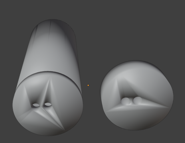
The barrels are a tube the length of 100mm the ir led is put in the middle hole in the tube and a color led in the offset one and the back is fitted over them holding them down and some tape can be used to hold the back on temporarily and the tubes can be slid in to the barrel and secured with a screw from the outside of barrel into the back piece
6.3 Auxiliary Board
Use a reflow oven for surface mounted components and a solder iron for through hole components.Care should be utilized especially when some components may be sensitive to the heat of an iron, proper soldering techniques should be used. Once the board is constructed connect to the other labeled sub assemblies.
6.4 Programming
After manufacturing the board and connecting it to the teensy and barrels, program the teensy using the arduino source code in the OSF repository and the arduino IDE with the teensy.
7. Characterization Data
7.1 Live Tests
Over 50 tests, the blaster was able to successfully receive a shot package 38 times and was read by another gun in 45 cases. These tests were performed in the dark and were set up with the sensor in-line with the barrel over a distance of 10 ft.
8.Sponsors
Our sponsor was Respawn Tactical Laser Tag who provided us with all our necessary parts and electrical components. As such this product will be turned into them for future use in their arsenal.
9. References
Administrator, et al. “Milestag 2 Protocol.” OpenLaserTag, 27 July 2020, openlasertag.org/language/en/milestag-2-protocol/.