
Main Product Image:
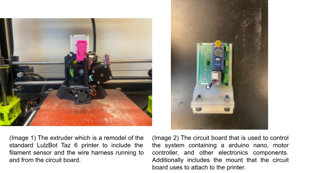
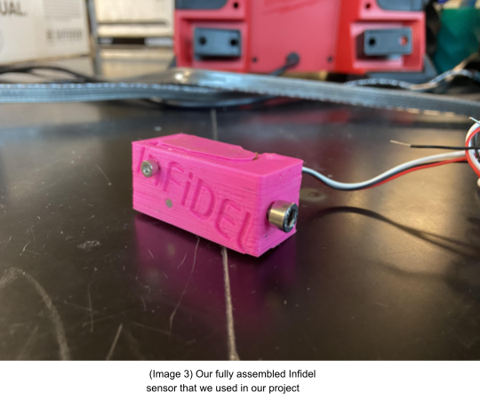
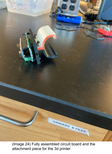
The Project includes an extruder assembly that can be attached to a LulzBot Taz 6 through the normal mounting and a circuit board that mounts on the back of the extruder plate. The extruder used the same build as the standard extruder except the wires are run from the plug to the circuit board and there is the addition of a filament sensor at the top of the assembly. The circuit board uses a perfboard that is mounted to a bracket that attaches to the back of the plate that the extruder itself is mounted to(both pictured above).
Project Description:
This project’s purpose is to develop a system that can be used with a LulzBot Taz 6 printer to passively adjust the rate at which the filament is extruded based on the diameter of the filament being used. This will allow for the use of filament with lower tolerances in diameter to have better print quality as the varying feed rate will keep constant volume and flow through the hot head resulting in less underfill and a constant extrusion rate. This project accomplishes this using an arduino nano to interface with the 3d printer itself, a stepper motor controller, and a filament diameter sensor.
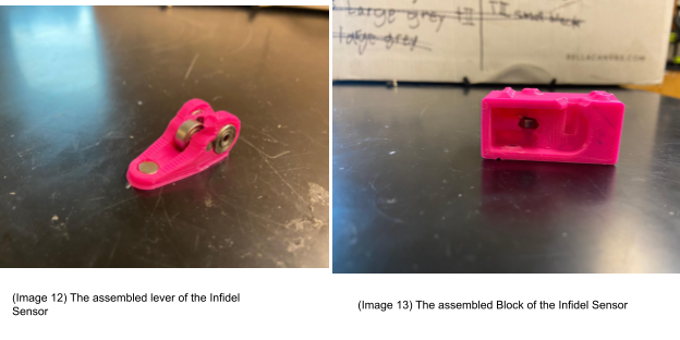
The filament diameter sensor uses a lever that has a roller bearing in which the filament passes under. At the far end of the lever there is a magnet inside of it that then changes the distance away from a hall effect sensor allowing for a readable signal by the arduino that varies based on the diameter of filament.
The arduino interfaces with the 3d printer itself to be powered and to intercept the signal being sent to the stepper motor to determine the set stepper motor speed by the system. It then uses the information gathered from the sensor to adjust this rate.
The arduino then interacts with a stepper motor controller to get the controller to send the signal to the motor of the updated rate calculated from the set rate in the 3d printer and the filament diameter.This interaction is all made possible through the use of a circular buffer to create a delay that matches the physical time it takes to get from the motor to the hot end. This entire process also happens in real time and can be added and removed from the printer at any time to be replaced with a normal head and does not change the 3d printer’s Firmware in any way making it usable on any LulzBot Taz 6 3d printer without modification.
Methodology in Brief:
Sensor design
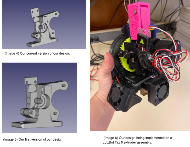
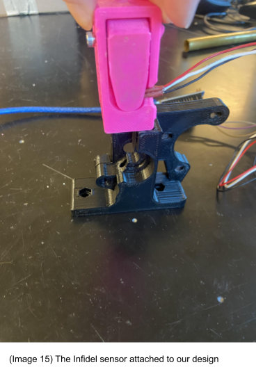
While recreaching a filament diameter sensor there were two different types of sensors that it went by. One was using a linear hall effect sensor and the other was using light sensors. In the previous semester a light sensor was used and proved to be inconsistent. Which made us go towards a hall effect sensor design. While looking at hall effect sensors an affordable open source option was found. Which was the Infidel Inline Filament Diameter Estimestar (low cost) sensor.
The infidel sensor brought us a few benefits. First, this was completely open source design. Which would extremely be beneficial to our enterprise cause. This design also has data already shared online. Which would make this design more promising results from it. This design is also low cost which is great for redesigning proposes and also fits within our budget.
Swappable Extruder Design
One of our first decisions was to push the design to be a swappable extruder design for a couple of reasons. First, It would take a significantly smaller amount of time to swap the extruder systems then adding our part to an already existing extruder system; which would have required the disassembly of each extruder every time we would want to use the extruder system. Another reason is that we were able to minimize the number of new components required. Especially since we would be changing out the stepper motor in the extruder system. This would also make it easy if we have to have any changes with the physical design or getting access to signals in the stepper motor.
Filament Diameter Sensor placement
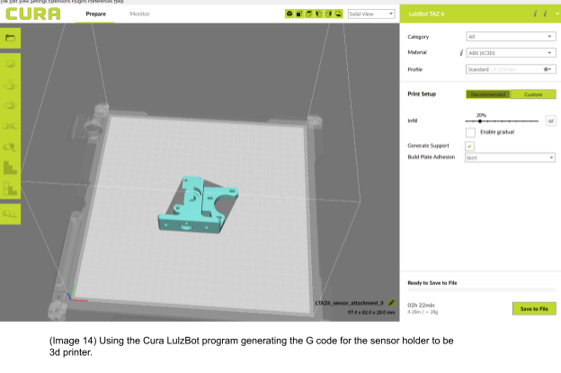
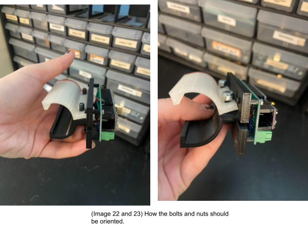
The filament diameter sensor must be placed along the filament. A fixed location was required so that we could get consistent data out of our sensor. This is also because there is a set circular delay of the stepper motor output signal based on how far the filament diameter is being read and the distance would be bigger than previous semester based on the change of the filament diameter sensor. To solve this we redesign one of the parts from the LulzBot Taz 6 by modifying the stl from the distribution center for the LulzBot Taz 6. We added a place in which the sensor could be attached by bolt and nut and be right above where the filament needed to be inserted. We had to disassemble the extruder to attach our new design to the extruder system.
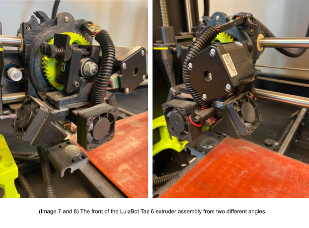
The design went through two different stages. The first design on the bottom has an issue in which the bolts would be too low and rub against the gear. So to solve this problem, the sensor was moved higher to prevent any damage. The only issue with this design is that it is fragile which might become an issue in the future. This is noticed while attaching the extruder system to the 3d printer.
Circuit board placement
For our project we would have to look at how our custom circuit board was going to be attached to our system. We were originally thinking of attaching the circuit board to the extruder system but decided against it because of the limited open space on the extruder.
On the Taz 6 there are limited options on the 3d printer. There is not a lot of surface area to attach the circuit board. With the design that the LulzBot Taz 6 has it would be very difficult to redesign the whole extruder system without breaking anything. The volume of the extruder system could not be changed since there are so many moving parts. We went through a couple of ideas to try to come up with solutions. First the circuit board is going to be attached nearby or on the filament diameter sensor. This would solve the issue and the area of the circuit board and the space that would be taken up would be minimal. However this was later proven that the system would have too much weight on it causing pieces to snap off the extruder system which was not affordable. Then the idea of attaching a piece to snap onto the motor. This was quickly noticed that the motors would heat up and possibly melt off the plastic which is not good. We then saw the potential of attaching it to the back of the 3d printer and having the wires brought to the back of the 3d printer. This would have a lot of surface area and we would not have to worry about the area that the circuit board would take up.
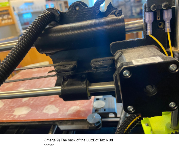
This was done by designing a snappable part. The part would grab onto the 3d printer while it was moving and was easy to pull off and put on. This had two complementary pieces that were around the same radius of the back of the 3d printer. The pieces were attached by bolts and lock nuts so the piece can not loosen.
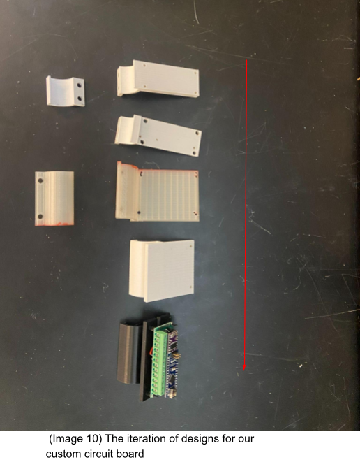
There were multiple iterations of this design. The design started out too small for the circuit board and was not stable enough for the board to attach. The third design worked but we were worried that it would take too much space on the top of the 3d printer. So with our current design it takes up less vertical space and works well.
Circuit Design
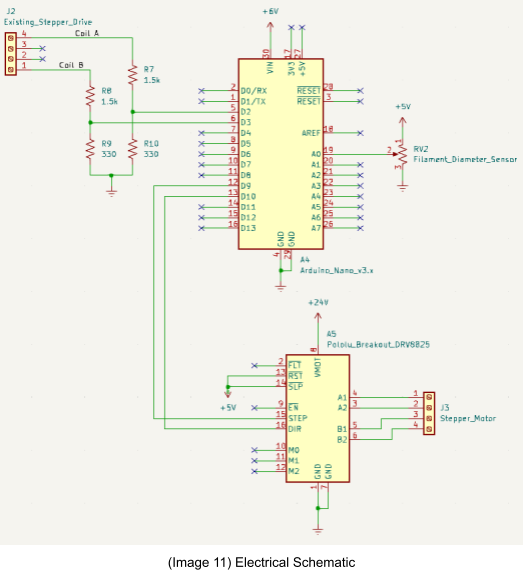
The circuit aims to intercept the signal to the extruder motor and replace it with a new one that accounts for the diameter of filament. There are three main components, the Arduino Nano where processing takes place, the Pololu DRV8825 stepper motor driver, and the SS495A linear hall effect sensor.
The hall effect sensor is modeled as a potentiometer in the diagram because a potentiometer was used to test it. It functions similarly as it is given a 5V input and outputs a different voltage based on the filament size.
The intercepted signal has a voltage much higher (24V) than the Arduino can handle (5V), so a voltage divider is used to reduce the voltage into the Arduino to around 4.3 volts, safe for the arduino. The arduino can accept higher voltages in the “Vin” pin and 5V is often not enough to function properly, so it is connected to a source of about 6V or 7V. It is connected to ground as expected. It also accepts an input from the hall effect sensor to determine the filament diameter. It outputs a PWM signal to the stepper motor driver.
The stepper motor driver accepts the PWM signal, voltage sources (24V and 5V), and a ground. The “reset not” (RST with a line over it) and “sleep not” (SLP with a line over it) pins are connected to the 5V source to prevent constant resetting or sleeping. Either of these would effectively disable the driver’s output. The PWM signals from the Arduino go into STEP and DIR, which control when the motor steps and the direction it moves respectively. A new motor signal is generated and output directly to the stepper.
A previous design had the RST and SLP pins connected to ground instead of 5V by accident.
Arduino Software
The software for the Arduino board is developed within the free arduino 2.0 ide and primarily functions off of interrupts. There are three conditions that can cause these interrupts which are a change in the state of the coil A signal sent from the printer, a change in the state of the coil B signal sent from the printer, or the timer reaching the time limit. Any of these cases will trigger a set of instructions defined at the bottom of the arduino program. When one of these interrupts is encountered the program sets a flag to true signifying to perform a time critical function. This allows the function to be forwarded to the next main loop and allows for it to be processed in the next run of the main loop.
The main loop in the program is tasked with counting the number of interrupts, incrementing and de-incrementing counters, and protecting against rollover. It uses primarily if statements to check for flags or state changes and updates the circular buffer accordingly along with resetting flags and states. The program utilizes the number of interrupts and state changes along with the buffer to interpret the frequency of the input to base the output on due to the lack of hardware to determine the input frequencies directly. The actual movements of the motor are handled by the ISR (interrupt service routine) where it then only sets flags. This is to minimize the time spent within the ISR as to hopefully stay within the main for a majority of the time to keep track of all the variables and keep the circular buffer up to date weather moving forward or backwards.
Generally speaking the program reads the inputs from the filament sensor and calculates the error and ideal filament diameter and uses it to set the output frequency based on the read frequency being sent by the printer.
The ISR is a portion of the software that is called when an interrupt happens and is tasked with handling the interrupt and creating a response to the interrupt. An interrupt is a detected action that needs to be taken care of or responded to immediately so it pushes an interrupt to the kernel which stops the current execution and calls the ISR to resolve the interrupt and then returns to where the program was stopped at.
Bill of Materials:
| 6x2mm Magnets | Filament Diameter Sensor | 1 | $0.08 |
| 623ZZ Bearings | Filament Diameter Sensor | 3 | $2.99 |
| Part name/ part number | Descriptions on what the part was used for | Qty. | Cost of part |
| Spring From Ballpoint Pen | Filament Diameter Sensor | 1 | $1 |
| SS495A | Filament Diameter Sensor | 1 | $7 |
| M3x8 Screws | Filament Diameter Sensor | 2 | $0.19 |
| 3x40mm Pins | Filament Diameter Sensor | 3 | $0.52 |
| 3d Printed Block | Filament Diameter Sensor | 1 | 8 grams of filament |
| 3d Printed Lever | Filament Diameter Sensor | 1 | 2 grams of filament |
| LulzBot Taz 6 | For extruder system and printing bed | 1 | $4,950.00 |
| 3d Printed Electronic Holder | Circuit Board Attachment | 1 | 30 grams of filament |
| M4x10 Screws | Circuit Board Attachment | 2 | $0.44 |
| M4 lock nuts | Circuit Board Attachment | 2 | $0.30 |
| M2x20 Screws | Circuit Board Attachment | 3 | $1.35 |
| M2 Nuts | Circuit Board Attachment | 3 | $0.15 |
| 3D Printed Sensor mount | Filament Diameter Sensor Attachment | 1 | 31 grams of filament |
| DFR0010 | Microcontroller for processing | 1 | $9.90 |
| Jumper wires | |||
| Stepper motor driver | DRV8825 | 1 | $3.40 |
| 330 ohm resistors | 2 | $1.59 | |
| 1.5 K ohm resistor | 2 | $0.14 | |
| Bus bars | WM23664-ND | 4 | $16.52 |
| perfboard | 1 | $0.90 |
Tools Used:
This is a list of tools we used throughout the duration of working on the project. This will include the tool name, part numbers or type if there are any, and the estimated cost of the tool.
| Tool Name | Part Number | Cost |
| X-Tronic 5000 series | #5040-Xr3 or any soldering iron | $298.75 |
| Solder wick | Any | $7.99 |
| Solder suckers | Any or Teenitor Solder Sucker | $6.99 |
| Solder | Any 0.6mm Diameter 50/50 Lead Tin Solder | $11.99 |
| Oscilloscope | MSO6012A | $895.00 |
| Solder Stand with Helping Hands | Any that will work with you | $15.99 |
| Microsoft Excel | $159.99 | |
| Windows command prompt | Any cost of a windows computer | |
| Google drive (docs, sheets, etc) | $0 | |
| Arduino ide | $0 | |
| Notepad Application on Windows | ||
| LuzBot Taz 6 | $4,9500.00 | |
| Drill | Any drill (We used the Milwaukee brand) | $149.00 |
| Hammer | Any | $15.99 |
| 2mm Drill Bit | Any | $8.61 |
| Alen wrench | Would need 3mm and 2mm for removing bolts | $16.37 |
| Screwdrivers | Hex 2mm and Hex 3mm | $8.92 |
Assembly Instructions:
Step-by-step instructions for assembling the project, supplemented by images to clarify the process.
Infidel Filament Diameter Sensor
To make the infidel sensor all you need to do is to follow the instructions from the “Infidel filament diameter sensor” [2]. We printed our pieces using 2.85 mm PLA and used the recommended settings on the LulzBot Taz 6. In this process we did some filing to have the bearings fit inside the holes. Also be aware that you will not be able to remove the pins once they have been inserted.
After you have your sensor fully assembled. Find and print Restruder_container_v2.stl. We printed using 2.85mm ABS filament. We used the LulzBot Taz 6 and used the recommended settings.
Once you print out the piece take 2 M2x 8 bolts and screw the filament diameter sensor into a 3d piece. Make sure that the input is facing up.
Then once you have this you will have to go backward from the Lulzbot Taz 6 “extruder assembly” [6,7] and follow that until you can replace the piece. Then follow the instructions to assemble the extruder system and you are all set to go.
Circuit Board Construction
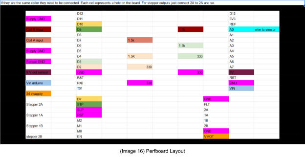
20 AWG solid core copper wire was used to connect the traces on perfboard. All cells of the same color in the spreadsheet should be connected. The cells are spaced to be consistent with the size and spacing of the perfboard. The cells with writing that have been left white are either not used or do not need to be connected with jumper wires.
After the wires are soldered, a multimeter should be used to check continuity in the intended locations. It is also a good idea to check for unintended shorts between other locations. Adjacent pins are especially likely to have a short.
Circuit board attachment
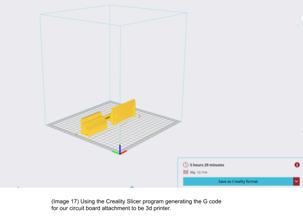
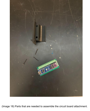
First you want to download the electronic_holder_clasp_v2.stl and electronic_holder_circuit_board_holder_v4.stl from our osf page ””. There are two options you can now do. Then you will want to print out the stls in a filament of your choice. We used the Ender 3 printer to print it out using 1.75mm PLA filament. We used the recommended settings and added the support setting on.
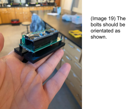
Once you have your part printed you want to grab these items. 3 M2x12 bolts, 3 M2 nuts, 2 M4x8 bolts, and 2 M4 nuts. First step is taking electronic_holder_circuit_board_holder_v4.stl and and attaching the circuit board using the M2 bolt and nuts.
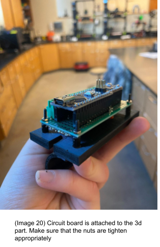
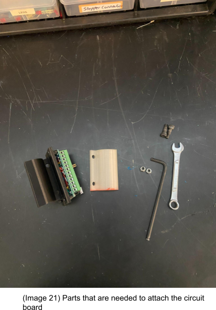
Then You will want to take your M4 Bolts and lock nuts and attach both of the 3d pieces together.
Make sure to tighten the bolts so that the board will not move easily. Also changing the nuts to lock nuts will help it from not getting the board loosen over time.
Characterization Data
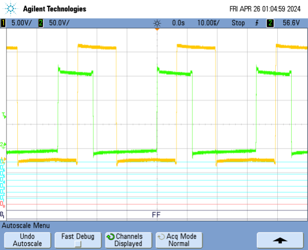
This is the resulting diagram that the oscilloscope shows when the system is being run on the test bench given ideal inputs with the latest updates to the design.
References:
[1]
“Pololu – DRV8825 Stepper Motor Driver Carrier, High Current (md20a),” www.pololu.com. https://www.pololu.com/product/2132/ (accessed Apr. 21, 2024).
[2]
T. Sanladerer, “Printables,” www.printables.com, Feb. 19, 2021. https://www.printables.com/model/57154-infiDANK (accessed Apr. 21, 2024).
[3]
SS490 Series Linear Hall-Effect Sensor ICs, Jun. 2018. https://4donline.ihs.com/images/VipMasterIC/IC/HWSC/HWSC-S-A0012708849/HWSC-S-A0012826823-1.pdf?hkey=82A29B72BDB3BD67C626B77C2F032848 (accessed Apr. 21, 2024).
[4]
“Index of /TAZ/6.0,” download.lulzbot.com. https://download.lulzbot.com/TAZ/6.0/ (accessed Apr. 21, 2024).
[5]
T. Harikkala, A. Nigrine, L. Manhart“Restruder – Fall 2023 Update,” Dec. 12, 2023. https://oshe.io/post/2937/restruder-fall-2023-update/ (accessed Apr. 21, 2024).
[6]
“OHAI: Open Hardware Assembly Instructions,” ohai.lulzbot.com. https://ohai.lulzbot.com/project/taz-6-extruder-assembly/ (accessed Apr. 21, 2024).
[7]
“OHAI: Open Hardware Assembly Instructions,” ohai.lulzbot.com. https://ohai.lulzbot.com/project/taz-6-extruder-full-assembly/hot-end-tool-head-assembly/ (accessed Apr. 21, 2024).
[8]
L. Manhart, A. Nigrine , T. Harikkala , and L. Galbraith, “OHSE Restruder,” Dec. 10, 2023. https://osf.io/4x3mk/ (accessed Apr. 23, 2024).