
Growbot – Open Source Hardware Enterprise – April 22, 2024
Eric Engebos (eaengebo@mtu.edu)
Nasi Koukios (adkoukio@mtu.edu)
Nick Kasi (srkasi@mtu.edu)
Hakeem Culberson (hiculber@mtu.edu)
1. Main Product Image
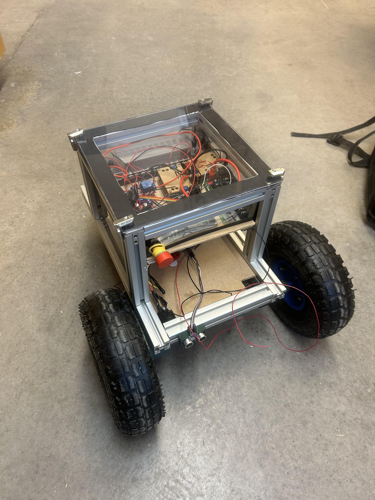
Figure 1: Grow-Bot
2. Project Description
The Growbot is a project created for the Open Source Hardware Enterprise at Michigan Technological University sponsored by General Motors. This team is focused on the planning and development of a water resistant remote-controlled robot. The Growbot is a proposed device that will be able to assist consumers with creating and maintaining small-scale gardens. The long-term goals of this project are for GrowBot to be able to traverse rough terrain, wet environments, and interact with the garden using an end effector. Growbot is a long-term project that has seen many revisions throughout the years. Our mission this semester was to make the electrical system much more robust and reliable.
3. Methodology in Brief:
Component and Layout Decisions
Before this semester, the Growbot was wired using a motor controller connected to the battery which supplied 5V to an Arduino MEGA. Then, a breadboard was powered with 5V from the Arduino, on which all sensors were connected. This distribution system presented several problems. First, the Arduino MEGA requires 7-8V for normal operation. Due to insufficient voltage of 5V, the robot would often encounter errors. For example, the receiver for the remote control was connected to the Arduino, communicating the signal from the controller. However, the robot often would not be able to respond to simple commands such as driving forward. The solution to this was to plug in the Arduino MEGA to an external power source such as a laptop. So, the electrical system required upgrades in order to allow the robot to move independently from a laptop powering the Arduino. In addition, the electrical system did not include safety features such as fuses or a killswitch. Finally, the breadboard pin system was not a reliable way to connect wires. They would often come undone, causing confusion on how to reconnect them.
Two decisions regarding layout involved buck converters and a fuse block. It was decided that for safety as well as more robust connections, a fuse block would be used for the initial 12V power rail. How many lines this block should be capable of connecting to was a source of discussion: there were several options ranging from 4 lines to 12 lines. In its current state, the robot required 3 lines to be used. However, to allow for future additions to the robot, a 12 line fuse block was selected.
The second decision was whether to (1) purchase one buck converter to power the Arduino and run sensors off of its 5V output, or to (2) purchase two buck converters and have the sensors separate from the Arduino power. The first option meant one less component, reducing costs and decreasing the amount of space and wires needed in the electrical box. The second option meant not drawing any more current from the Arduino and allowing for adjustable voltages instead of only 5V, but possibly introducing noise into sensor readings. The second option was decided upon for the ability to change the voltage freely, allowing more flexibility in the design.
Killswitch/Relay
After meeting with our sponsors, it was decided that the robot needed a killswitch to shut everything off at the press of a button. The killswitch we used was the A22NE-PD/A22NE-P/A22E [2]. The emergency stop switch, and pretty much all emergency stop switches, have a high resistance. The datasheet of our killswitch reported 10k ohms of resistance, but the actual resistance when measured with a DC multimeter was 66k ohms. Having a high resistance is bad due to a high voltage drop across the component, reducing the current that would flow through to the rest of the circuit. This can be denoted by Ohm’s Law, I = V/R. Therefore, a relay should be placed in between the emergency stop switch and the circuit. So, a relay was bought and used in the circuit. Figure 2 is a diagram showing the connections between the relay, battery, killswitch, and the fuse block (bottom left). We investigated layouts of many different relays, and found datasheets that corresponded closely with our specific relay (the HiLetgo 12V 1 Channel Relay) but contained more informative diagrams [3].
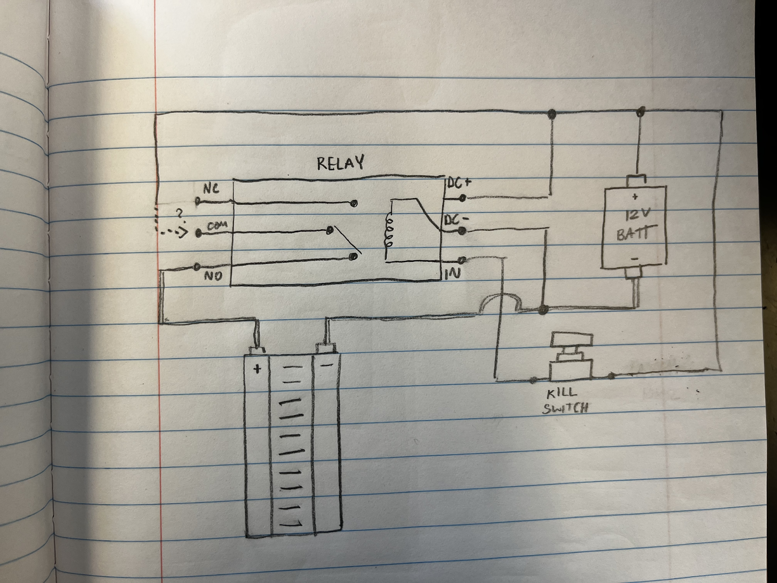
Figure 2: Killswitch pin layout
Fuses
The Growbot needs to have protections against events such as overcurrent. Therefore, the easiest way to protect against this event was to use fuses. Looking at documentation, the motors have a stall current of up to 6 amps. To confirm, the team tested how much current the motors would draw even under strain and found similar results. To avoid blowing a fuse during expected operation, it was decided a 7 amp fuse was used. The Arduino also uses a similar type of thinking: since it does not draw very high current a 1 amp fuse was sufficient. To easily replace the automotive fuses being used, a fuse block was bought.
Buck Converters
Power for the Growbot needed a bit more thought. 12V is needed for the motors, but the Arduino and the more sensitive electronics cannot operate at that voltage. So, to step the voltage down, a dc – dc converter needs to be used. Our choice was two buck converters. One of the buck converters was used for the arduino, and the other is for the smaller electronics. And to easily distribute the power, power rails were utilized.
Component purchases for the new power distribution system
| Item | Link | Per Unit Cost | Qty | Total Cost |
| Buck converter | Amazon.com | $16.99 | 2 | $33.98 |
| Fuse block | Amazon.com | $18.99 | 1 | $18.99 |
| Relay | Amazon.com | $5.89 | 1 | $5.89 |
| Distribution Rail Line | Amazon.com | $13.99 | 1 | $13.99 |
| Total | $72.85 |
4. Bill of Materials (BOM)
Bill of Materials | |||||
| Category | Item | Link | Per Unit Cost | Qty | Total Cost |
| Mechanical | 30 x 30 mm T Slot Rails | Amazon.com | $25.00 | 2 | $50 |
| 10 in Pneumatic tires x 2 | harborfreight.com | $8.49 | 2 | $16.98 | |
| 5 in Caster Wheels | In store Harbor Freight | $8.99 | 2 | $17.98 | |
| Axle Rods | Amazon.com | $8.99 | 1 | $8.99 | |
| 8mm Skateboard Bearings | Amazon.com | $9.59 | 1 | $9.59 | |
| 8mm Linear Rail Stop Collars | https://a.co/d/4P2c1dW | $13 | 1 | $13 | |
| Adhesive Foam Rubber Sheet | Amazon.com | 12.99 | 1 | 12.99 | |
| Electrical | Milwaukee 12V Battery Adapter | https://a.co/d/a3XeQW0 | $13 | 1 | $13 |
| 634JSX‑31ZY Motor and Gearbox | https://www.aliexpress.com/i/2251832136653723.html?gatewayAdapt=4itemAdapt | $32.29 | 2 | $64.58 | |
| Arduino Mega | Arduino.cc | $41.14 | 1 | $41.14 | |
| L298N Motor Drive Controller 4pcs | https://tinyurl.com/56w9rc46 | $11.49 | 1 | $11.49 | |
| FLYSKY RC Transmitter Controller | Amazon.com | $52.99 | 1 | $54.99 | |
| Buck converter | Amazon.com | $16.99 | 2 | $33.98 | |
| Fuse block | Amazon.com | $18.99 | 1 | $18.99 | |
| Relay | Amazon.com | $5.89 | 1 | $5.89 | |
| Distribution Rail Line | Amazon.com | $13.99 | 1 | $13.99 | |
| Total Cost | $387.58 | ||||
Currently, the project is not very accessible due to the high cost of reproduction. Most notably, the T Slot Rails, Motors, Arduino, and Flysky are very expensive components.
- Though a different material could be considered for assembly, compromising the strength of the frame would affect the durability. One alternative could be to reduce the size of the robot, decreasing the materials needed as well as reducing weight.
- The electrical components were chosen for ease of implementation. The Arduino has extensive documentation and the FlySky controller and receiver are very intuitive to set up. To reduce costs, less expensive components could be selected, but assembly instructions must be very detailed to ensure anyone replicating the design has a sufficient explanation to set up the components.
- Finally, the cost is inflated due to purchasing more material than needed. For example, the adhesive foam rubber sheet linked is 12 inches wide and 48 inches long. This is way more than actually used on the robot. Purchasing components in smaller quantities is another way to reduce costs.
5. Tools Used
| For testing | Part Number |
| Multimeter | The Fluke 187 True Rms Multimeter was used, but any multimeter can be used. |
| DC power supply (12V) | E59CDCBB |
| Oscilloscope | The MSO6012A mixed signal oscilloscope was used, but other oscilloscopes can be used. |
| For building | Part Number |
| 3D printer | The Lulzbot Taz (1942-KTPR0051NA-ND) was used, but any 3D-printer can be used to print the parts. |
| Flathead screwdriver | Flathead screwdriver (308852) was used. Although any Flathead Screwdriver that is ⅛ will work for the application |
| Phillips screwdriver | Phillips screwdriver (20837688 ) was used. Although any Phillips Screwdriver that is within the size requirements will work for the application |
| Cutting tools (Exacto knife, and Swiss army knife) | An Exacto blade was used (X3202) to cut thin plexiglass although any sharp cutting tool will be able to achieve the same result. |
| Wire strippers, | The Wire Strippers (1597-1537-ND) although any wire strippers that can cut 14-22 gauge wire will work. |
| Connector crimpers | The crimper used (660001014100) |
| Soldering iron | The Soldering Iron used was the (5040-XR3) Although other irons can be used to solder the wire connections. |
| Electrical tape | ½ inch tape was used. 1 inch can also work along with not needing a specific brand any electrical tape will work. |
| Power Drill, Drill bits | A Milwaukee Drill was used (2902-20). Although any power drill can be used to cut through the plexi glass. For the drill bits a multi size kit was used (20836961). |
| Software | Version |
| Arduino IDE | Arduino IDE – 2.3.2 |
| KiCad | KiCad – 8.0.1 |
| QCad | QCad – 3.29.6 |
| FreeCad | FreeCad – 0.21.2 |
6. Assembly Instructions
On the Open Source Hardware Enterprise website (https://oshe.io/post/2765/growbot-fall-2023-update/) most of the steps to replicating the Grow-Bot can be found in the Fall 2023 update. Those steps are included below. In addition, we added steps to further the design.
Mechanical:
- Assemble chassis
- Cut 30mm T Rails into correct sizes
- A – 2 x 18in
- B – 4 x 8in
- C – 6 x 9in
- Put rails together as shown using 90-degree T slot connectors
- Cut 30mm T Rails into correct sizes
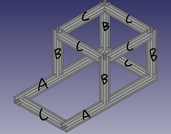 | 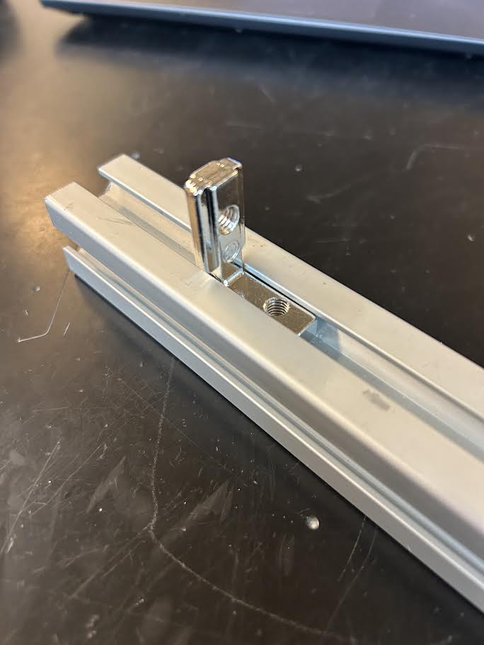 |
| Figure 3: Frame Diagram | Figure 4: T Slot Connector. |
3D-Print wheel mounts, wheel hubs and actuator gears
- Parts from the OSF Repository (https://osf.io/28dq4/)
- 2 x Front wheel mounts (wheelMount_fall_2023.FCStd)
- 2 x Front wheel mounts (wheelMount_for casters.FCStd
- 2 x Wheel hubs (wheelHub.FCStd)
- 2 x Actuator gears (gears.SCAD)
- Total print time ~50 hours
 |  |
| Figure 5: Motor housing and gears | Figure 6: Wheel hub |
Attach bearings to wheel mounts and mount motors
- Attach bearings to both sides of the wheel mounts
- May also require some persuasion
- Mount motors using M4 x 10 screws
- Slide wheel mounts on to T Slot rails and lock in place using T Slot locking hardware
Replace wheel hubs
- Remove the screws holding the harbor freight wheels together
- Remove just the side with the bearing
- Insert axle rods into printed wheel hubs (May need some persuasion(A hammer))
- Make sure to do this before putting wheel hubs together
- Use M6 screws and nuts to secure printed wheel hub to the remaining original hub
Add wheels to mounts, add actuator gears
- Slide axle rods through skateboard bearings
- Add actuator gears to motor and axle rods
- Attach 5 inch caster wheels to the back of the robot frame
Cut a 13 x 13in plexiglass cover to use as a water resistant cover for the electrical box
- Cut the adhesive foam to run along the edges of the electrical box to help keep water from running underneath the plexiglass cover
- Attach the new water resistant cover with L-Brackets
- Cut plexiglass for the walls of the electrical box. Drill a hole on one side for the killswitch to fit.
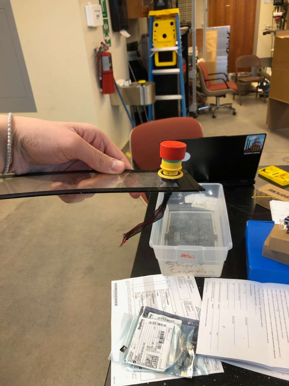 | 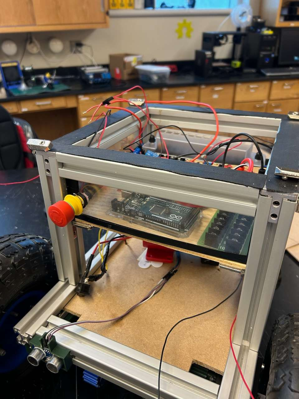 |
| Figure 7: Mounted kill switch | Figure 8: fully Assembled Grow-Bot |
Electrical:
- A wiring diagram (Figure 9) was created with the open-source software KiCad (https://www.kicad.org/). A PDF as well as the modifiable KiCad file can be found on the OSF repository (https://osf.io/28dq4/).
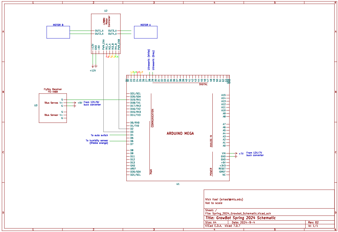
Figure 9: KiCad Drawing of Pin connections
- A layout diagram (Figure 10) was created for the Electrical Board made in QCad (https://qcad.org/) with the parts ordered in Spring 2024. A PDF as well as modifiable QCad file can be found on the OSF repository as well.
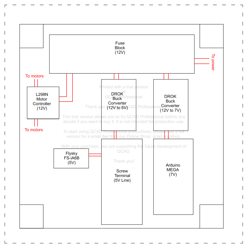
Figure 10: QCad diagram of all components to scale with power connections in red.
The Growbot includes the following electrical components:
- Arduino Mega
- L298N Motor Controller [1]
- FS IA6B Flysky Receiver
- 2x Motors
- Switch
- Kill Switch [2]
- 2x DROK Buck Converter 12v to 5v
- PCB005 1X Power Distribution Board 3 Inputs 2 x 10 Outputs for DC AC Voltage
- 12 Way 12V Fuse Box Blade
- HiLetgo 12V 1 Channel Relay Module
7. Characterization Data:
| Objective | Passed/Failed | Notes |
| The killswitch cuts off current when pressed | Passed | Initial tests yielded the opposite result: The current would only flow when the killswitch was pressed. This was resolved by connecting the positive line of the fuse block to “Normally Open” on the relay instead of “Normally Closed.” We used a DC power supply to run current through the circuit and test the killswitch.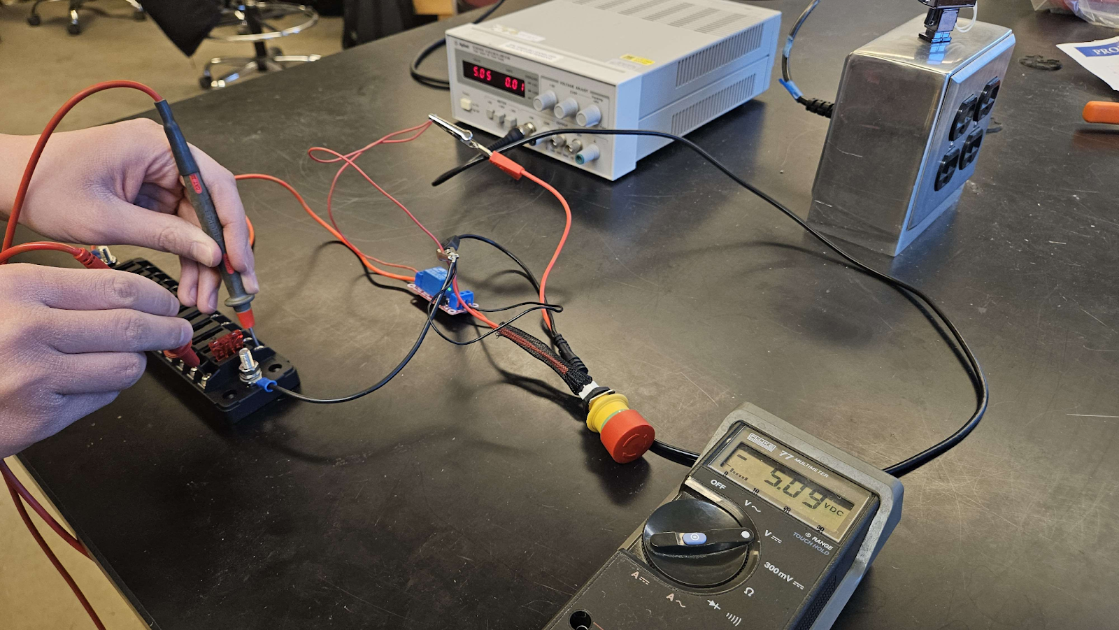 |
| The killswitch allows current when opened | Passed | |
| The fuse block provides 12V of power | Passed | Components requiring 12V such as the motor controller runs directly off of the fuse block. Smaller devices such as the receiver and sensors run off of the 5V distribution rail. The distribution rail becomes 5V after using a buck converter to bring down the voltage. |
| The sensor distribution rail provides 5V of power | Passed | |
| The arduino is receiving 7V power in | Passed | Before upgrading the electrical board, the Arduino would not receive sufficient power (5V instead of 7V). This meant that the robot would not respond to inputs from the controller on its own, and an external power source would need to be plugged into the arduino. This has been resolved and the robot now responds to the controller independently. We resolved this by using a buck converter to reduce the voltage from the fuse block to 7V from 12V and then connected the output of the buck converter to the arduino. |
| The flysky controller and arduino communicate | Passed | |
| The flysky receiver outputs a default value when disconnected from the controller | Passed | Initially, when the controller and receiver were disconnected (whether by moving out of range or turning off the controller), the receiver would continue outputting its most recent signal. This was resolved by modifying “default case” settings on the controller. Now, the receiver will output a default value that confirms the controller has been disconnected. |
8. Open-Source Principles:
All files were created using Open-Source software. All design files are available online with the OSF repository. The design process and documentation of roadblocks is available on oshe.io with the Growbot team’s work logs.
Overall, the project is not extremely replicable due to cost of parts, but all of the components are purchasable and no extensive manufacturing is needed. It is well documented.
The decision making and iterations of the robot can be found in the team’s work logs.
Nick Kasi: https://oshe.io/post/4096/nick-kasis-work-log/
Eric Engebos: Eric Engebos Work log
Nasi Koukios: https://oshe.io/post/1481/nasi-koukios-work-log/
Hakeem Culberson: https://oshe.io/post/3329/work-log-hakeem-culberson/
9. Sponsors/Acknowledgements:
This project was sponsored by General Motors in 2020.
We would like to thank the individuals at General Motors who offered their expertise and gave us feedback during regular meetings.
Jason Biehl
Zachary Arnold
Drew Vincent
10. References:
[1] “L298N Motor Driver Module.” Components101, components101.com/modules/l293n-motor-driver-module. Accessed 18 Apr. 2024.
[2] Emergency Stop Pushbutton Switches (22-Dia. or 25-Dia.), assets.omron.eu/downloads/datasheet/en/v7/a22e_a22ne-p_aa22ne-pd_datasheet_en.pdf. Accessed 18 Apr. 2024.
[3] 1 Channel 5V Optical Isolated Relay Module, https://handsontec.com/dataspecs/relay/1Ch-relay.pdf (accessed Apr. 18, 2024).