
Tuesday, September 19, 2023
We met with Nick Sandahl and Adam Sandahl, two members of OSHE that worked on Growbot the previous semester (Spring 2023). Though they are working on new projects now, they agreed to help us understand some existing parts of the Growbot. After trying to puzzle out a breadboard and old versions of the code, we ultimately got the robot to power on and spin the front wheels while Nasi held up the back of the robot (it is currently missing back wheels so we had to improvise). We were using a joystick with very inconsistent responses for moving forward, backward, and turning.
We decided to purchase certain components. We need a new FlySky controller as the one from previous semesters is broken, and the joystick really isn’t cutting it. In addition, we need swivel wheels for the back of the robot, since it is using front wheel drive and thus the back does not need motors. We also need foam for the water cover and a new axle.
The rest of this log will contain notes that we took while trying to get the Growbot moving again.
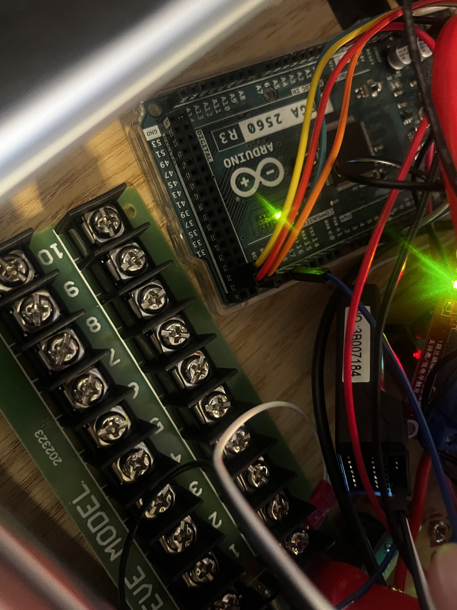
Motor Controller:
- 4 Cable input (Red, Orange, Yellow, Green)
- These cables are connected on the side of the motor controller that I will call the “front.” It is facing the direction of the ultrasonic sensor at the front of the robot. Two cables are controlling Motor A, two are controlling Motor B.
- When all 4 lines are high or all lines are low, the motors will stop.
- The 2 cables on each side of the 4 cable input are PWM. The PWM controls the speed that the motors will run at. One cable controls Motor A, the other controls Motor B.
- You can see in the code which Arduino pins each wire connects to.
- Note: Make a schematic so you don’t have to look at the code every time!
- On the motor controller, there are yellow wires coming out of 3 sides. The front two are going to the battery. The ones on the side go to different sides of the motor.
- To re-iterate, each pair of wires on the right and left side of the board connects to one motor (motor A = left, motor B = right) (Black tape indicates ground.)
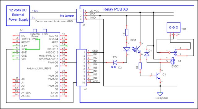
- The front of the controller has an extra 5V port to power the Arduino. It is next to the 12V battery inputs.
- RISK: IF YOU ARE CHANGING THE BATTERY FROM 12V TO HIGHER
- (The 3 “input” pins on the front side of the board, if you are looking at it from the front: the left is high, middle is ground, right is the 5V)
- Remove the black jumper pin right behind the terminals (which will remove the 5V line)
- If you don’t remove the jumper pin and make the input higher than 12V, then the board gets fried! Don’t do that!
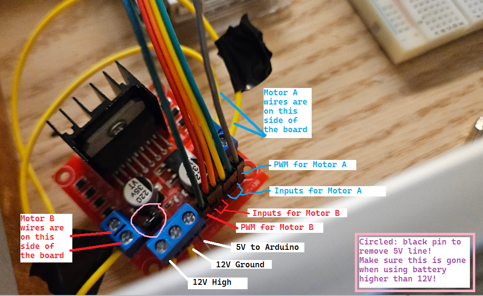
- Note: Take a photo of the motor controller and label the different ports! But please make it look nicer than this, I used MS paint.
Code:
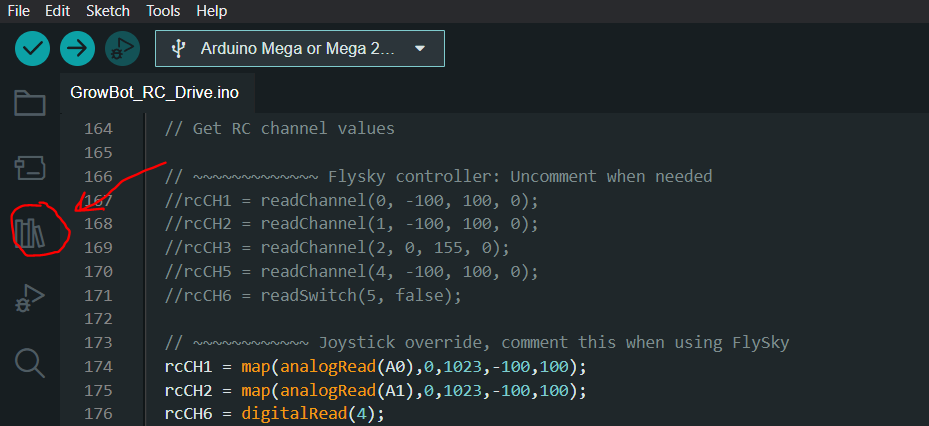
- There are several sections of code commented out, usually involving something called “iBus.” This is code configuring the FlySky controller. Since we don’t currently have a FlySky controller, the code is using a single joystick. When you convert back to using FlySky, comment out the joystick code and un-comment out the FlySky code.
- We were viewing the code in the Arduino IDE (Nightly) which can be found on the arduino website. The code itself was found in the google drive under the “Arduino” folder. The code has since been modified, but this was the the base.
- Note: Put the new version of the code in the google drive!
- When verifying the code for the first time, a common error you will face is that certain libraries cannot be found in the code.
- Click the “library” button on the left side of the screen (see image below), and look up the library that is causing issues. Then, hit “install.” If it still doesn’t work… We just installed a bunch of similar-sounding libraries until it worked eventually.
- In this post made by the previous Growbot team, there is a table at the bottom of the page showing links to various tools. If you are still having issues finding libraries for the ultrasonic sensor or the humidity sensor, start looking there.
Possible future changes that we discussed but aren’t planning to implement any time soon:
- Add another electronics board on the bottom of the robot for a more organized way to connect to sensors/motors. Currently there is quite a distance from the top electronics board down to where the components are, and it can get messy or tangled/disconnected.
- Power the arduino seperately from the motor controller using a DC to DC buck converter. The arduino MUST have 5V or less to avoid damaging it, so we need to convert from the 12V battery.
That’s all for September 19th!
Thursday, September 28, 2022
This week, my grand mission was to get the FlySky Controller working. We ordered a new controller, but Dr. Shane also allowed us to use the controller of a decomissioned project: The quadcopter. However, we still needed a receiver, so for testing purposes I used the receiver of the new controller. (It ultimately doesn’t matter which receiver and which controller is used, they can be paired.)
Also, today I emptied out the Growbot cabinet to inspect everything inside and try to find the old receiver. I could not find a receiver, but there are many unused parts in the cabinet that might be able to be removed to clear up some space. I also put all loose cables in a plastic bag, so it is easier to find something to use when needed.
I used this website as a starting point. To bind the receiver and the controller, I used this video.
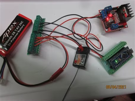
- Connecting the receiver to the Growbot
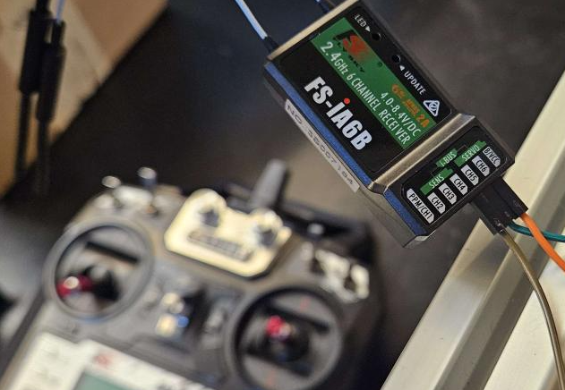
The receiver looks like this (See above). In the background of the image, you can also see the quadcopter FlySky controller that I was using. In order to hook it up, 1 pin needs to be connected to the Arduino MEGA, and 2 pins need to be connected to some kind of power source. In this case, I was connecting it to the 5V and Ground lines on the breadboard.

In the code, you will find the location to plug the receiver into the Arduino MEGA. This is our “iBus” and it is Pin 19 in this image.

- Pairing the Receiver with the FlySky controller
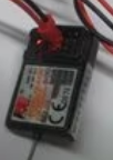
Now, when you turn on the robot, the receiver will have a flashing red LED. In order to pair it with the controller, you can connect the binding key to the rightmost 3 pins on the receiver (see below).
When the FlySky controller is off but the receiver is on, press and hold the binding button on the bottom left of the FlySky controller. While holding this down, turn on the controller. It will go into “binding mode” and find the receiver.
- Issues
The FlySky controller would play display that the receiver had no power (RX and an empty battery symbol on the screen). I charged the Growbot Battery but this problem persists. It is possible there is a certain voltage level that the controller expects. If there is a way to lower the voltage threshold, it may remove this issue. Until this issue is solved, it will be difficult to test controls. However, the receiver and controller both turn on and recogize each other.
Another issue is the organization of the breadboard. I am struggling to find a way to plug in the receiver that does not cause visibility issues and further confusion: We are going to have to do a lot of wire management.
- Future plans
We have been working on waterproofing the robot by cutting new covers and ordering a foam seal to ensure no water can enter the electronics enclosure. In addition, we have been working on our presentation for the Critical Design review. We are reconsidering using caster wheels for the back wheels of our robot due to traction issues. Ultimately we hope to get the robot moving using the controllers and let it stand on its own 4 wheels (instead of the 2 it is currently using).
Friday, October 6
This week there was more work on the FlySky Controllers, the waterproof cover, and some repairs.
- Issue with the FlySky alarm
Last week, it was noticed that the FlySky controller would successfully bind to the receiver, but it would constantly sound a warning that the receiver had no battery. Despite it being difficult to find people with similar issues online, we found a way to prevent this from happening. First, operating the menu on the controller was a bit difficult, so this website clarified that holding down the “cancel” button would confirm a selection. Then, in the settings the threshold at which a low power alarm would sound would have to be reduced. The low power may be an issue in the future, but it is difficult to troubleshoot when an alarm is constantly going off. The steps are as follows:
- Hit “cancel” several times to return to the main screen
- Long press the OK button to open the menu
- System>RXsetup>RXbattery
- On both the external and internal sensors, set “Low” and “Alarm” as low as possible (0 or 0.1)
- Long press cancel to confirm
Afterwards, we ran the new code on the Arduino to see if the robot had any response to the controller. The results showed that the robot would run backwards until the FlySky controller was detected, at which point it would stop. When the right joystick was moved, the motors would turn extremely slowly, almost imperceptibly. However, it was a sign that the robot was indeed receiving signal from the FlySky.
(Note: Adjust “default” cases so the robot does not continuously run. Find out if the slow motor response is due to battery issues or code issues.)
A few other issues were discovered during testing. The robot seemed to run out of battery, so it was recharged, but after re-attaching the battery the robot would refuse to turn on. Nasi discovered that the power switch had been disconnected from its wires, and fixed it with some soldering. Eric worked on the waterproof cover and securing it to the frame.
- Future plans
For next week, we will be presenting our Critical Design review. In the future, we want to get the caster wheels on the robot and the FlySky more reliably controlling the driving. In addition, we need a more permanent way to secure the receiver.
Friday, October 13, 2023
This week, we presented our Critical Design Review. We received a lot of important feedback on our project, so we re-assessed our plans.
Planning
Here are some possible modifications to our plans for the rest of the semester:
The objective of the project for Fall 2023 are the following:
- The entire device will have design files that originated entirely from free and open source software.
- The electronics will be secured – Achieve a robust packaging of electronics
- The electronics should not move or disconnect while the robot is in motion.
- The Arduino Mega and the Breadboard are currently secured with tape, the motor controller has a 3d-printed housing, and the battery is connected with velcro.
- The wooden electronics housing can be converted to plastic (PVC or ABS board), the breadboard and arduino will be secured with screws and spacers
- The electronics will be organized – The electronics packaging will be optimized for a modularity and accessibility
- Each component has its own location, and wires are neatly organized.
- Replace breadboard with connector that is secured to the board. Board connector: https://www.amazon.com/Terminal-200v-450v-Terminals-Connectors-GUBCUB/dp/B09VSYWFFM?th=1
- Arduino pins: https://www.amazon.com/DGZZI-50pcs-Terminal-Connector-Arduino/dp/B07SZFGH4B/ref=sr_1_4?crid=GEVQSM82G2WA&keywords=dgzzi+pcb+mount+screw+terminal+block&qid=1697235293&sprefix=dgzzi+pcb+mount+screw+terminal+block%2Caps%2C149&sr=8-4
- Organize/optimize wire routing from electronic modules to connector and to the arduino
- Create new wiring diagram in KiCad
- Update with all modifications to the electrical circuit.
- FlySky receiver
- 5V Power line from Motor Controller
- Remove components that are no longer on the robot
- Update with all modifications to the electrical circuit.
- Replace damaged gears
- Evaluate if there is a stronger material available to print, else print multiple so that replacement gears are available
- The robot can be powered on safely
- Add a circuit breaker/fuse on Hot side of battery
- Add a circuit breaker/fuse on 5V line to Arduino mega
- Arduino mega: 100mA
- Check power consumption of Motors (Make sure Multimeter is measuring using the right pins OR use the lab clamp thingy from Lab 5, b/c multimeters can’t always measure high current)
- Measure current on 12V battery when motors are not running
- Measure current when motors are running (difference is motor)
- Double total amperage for fuse value
- Improve maneuverability of the robot
- Attach swivel casters for back wheels
- The electronics enclosure has a water resistant cover
- Extra sealing with gasket
Code
In addition to this planning, troubleshooting for the code continued.
When the flysky controller is off:
- If the robot turns on when Auto mode is DISABLED, nothing happens
- If the robot turn on when auto mode is ENABLED, it will go forward (even if the auto switch is subsequently turned off)
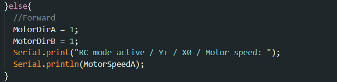
The code was modified to test if Auto mode switch can affect robot operation. A second “else” (image below) was added to disable motors when the auto switch is off. It would stop the motors, but they would make a jerking, clicking sound.
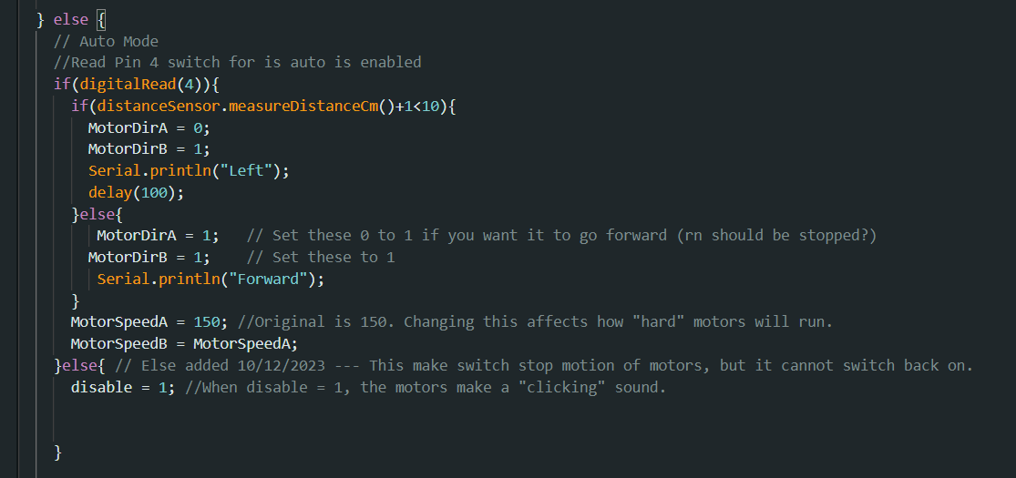
Once it detects the flysky controller, it will no longer run normally, and usually have either “jerky” motion or no motion at all (when right stick is moved).
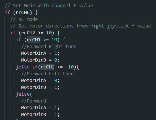
- Potential solution: Modify motor speed within the code instead of motor direction. (Image below shows FlySky code affecting Motor direction.)
Next week, we will discuss plans regarding removing the breadboard and attaching wheels, as well as learning more KiCad to update the schematic.
Wednesday, October 18, 2023
The code has been sucessfully troubleshot! Trouble…shooted? In any case, the past few days many more issues have arisen, but a lot of helpful information was gained.
Physical issues
- The motors appear to struggle moving, and it is not code-related this time. Even in auto mode where they would run continuously, the left motor is not making any sound or movements, and the right motor is making faint sound but not moving.
- We will have to detach the motors and test them individually, as well as checking the wires for any issues. If the problem is the motors themselves, we will need replacements.
CAD
- The CAD for the motor mount is located in the Shared Growbot drive under Growbot>CAD>Fall 22>wheelMount_2.4.FCStd
- Eric is working on re-printing the cracked front housing and adapting it for our back wheels.
Code
- After consulting with Adam Sandhal, he suggested that we use the Serial Monitor to see if the issue is signal strenth, code, or a physical problem.
- To use the serial monitor, you can open it in Tools>Serial monitor in Arduino IDE and setting the baud to 9600.
- In addition, the baud in the code must be 9600 (Where it is written: Serial.begin(9600)).
- If this is not the case, the monitor will output a bunch of junk. (See below).
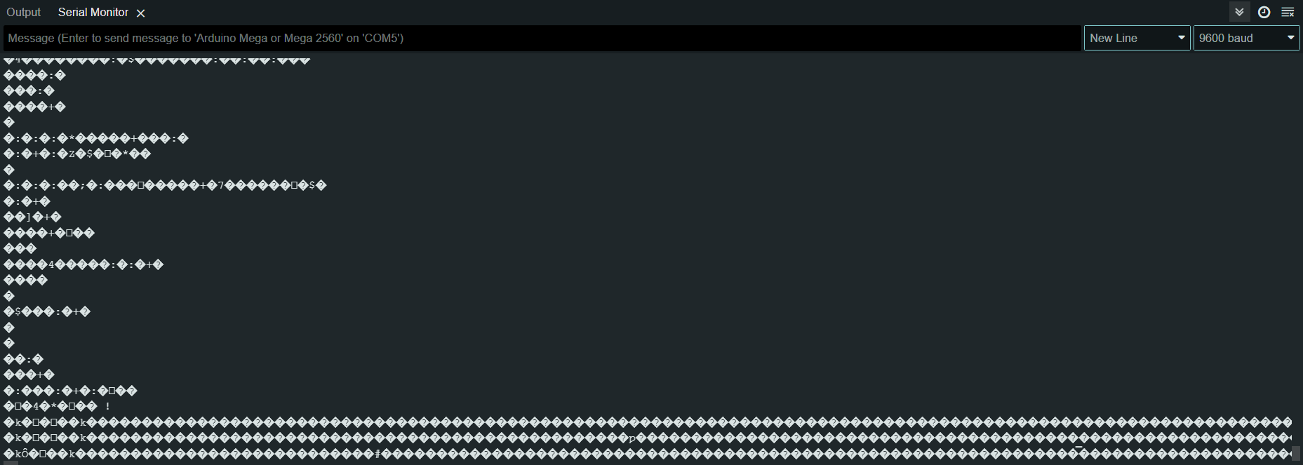
- Once the baud is successfully set, Serial.print(“Whatever you want to print”) can be inserted into the code where needed.
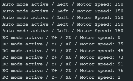
- I added serial print for all situations of Auto mode and RC mode. I quickly found that turning the right knob all the way counter-clockwise turns OFF RCCh6, and turning it all the way clockwise turns ON RCCh6. So, when the knob is around 11PM, Auto mode will be enabled, when the knob is around 8PM, RC mode will be enabled.
- The serial monitor pretty clearly shows that the arduino can sucessfully detect when the right stick of the FlySky controller is giving inputs. So, the issue is not the signal between the two devices, and the code is setup correctly. (Below, the serial monitor switching from auto mode to RC mode and displaying different motor speeds as the right stick is moved more or less.)
Here is the section of the code that shows serial print when the Y is positive and the X is 0 on the right stick:
- However, the motors still do not run. Next time we will start working on removing the motors for physical testing.
Timesheet
- We also created a timesheet for the remaining weeks in order to create goals to work towards and tentative deadlines. The timesheet is not finalized but it is good for keeping track of what everyone will be working on that week.
Returning 6inch casters
- I will be returning the 6inch Casters next Wednesday.
October 24, 2023
GOOD NEWS! The RC code is now working. UNFORTUNATE NEWS: Many weeks were spent agonizing over a SINGLE LINE OF CODE.
I will first explain the working solution, and then I will explain the previous attempts.
CODE
- The code for the robot is focusing on one variable: rcCH6. This reads a certain value from the controller. When chCH6 is high, it means the controller is connected and RC mode is active. When rcCH6 is low, it means the controller is not detected, and autonomous mode is active.
- The robot will only turn the motors when it is ENABLED (disable=0) in the code: this had to be placed once rcCH6 was detected.

All we needed was this disable = 0… I would like to dedicate this success to Adam Sandhal who looked at the code for 2 minutes and immediately figured it out. This is why you ask people for help as soon as possible, folks.
Anyway, today we also spent some time fixing the motor issues from the previous week.
- First, we removed the motors and Nasi checked the electrical connections by removing the insulation and testing the motors with a Multimeter. He confirmed that the components themselves were fine, and added insulation back to the wires.
- Eric figured out that some pins on the Arduino were disconnected (the data pins for Motor B on the arduino had come loose from pin 25). After re-connecting this, the motors ran fine in autonomous once again.
Future code issues
- Now that the robot could reliably switch to RC mode, we faced the issue where it could not switch BACK to auto mode once the controller is disconnected. Maybe this was because rcCH6 would simply stay high once the controller disconnected. We attempted to remedy this in the code by resetting the channel back to low each loop. However, if the receiver is still reading “high” when the controller is disconnected, this value will be updated again, so ultimately this was removed from the code.
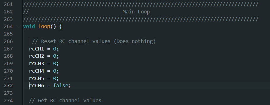
Attempt at fixing the switch back to auto mode shown on lines 267-272 on the image above, did not work so it has been removed.
- Next, we added more Serial Prints to show us in what states rcCH6 would read as high.
- Turning on the robot with the controller on: 1
- Then, turning off the controller: 1
- Turning on the robot with the controller off: 0
- Subsequently turning on the controller: 1
- Then, turning off the controller: 1
- Turning on the robot with the controller on: 1
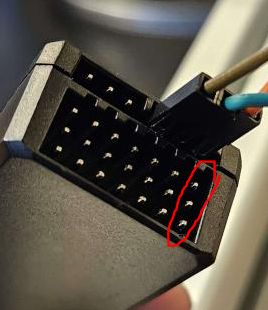
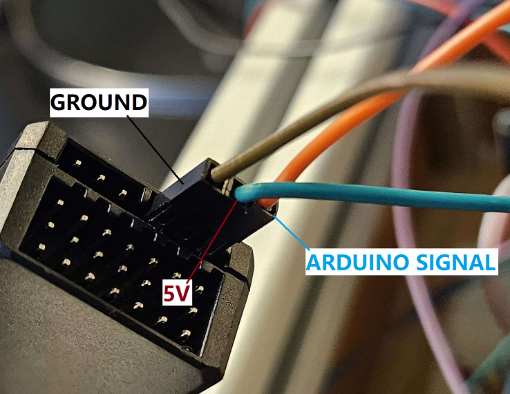
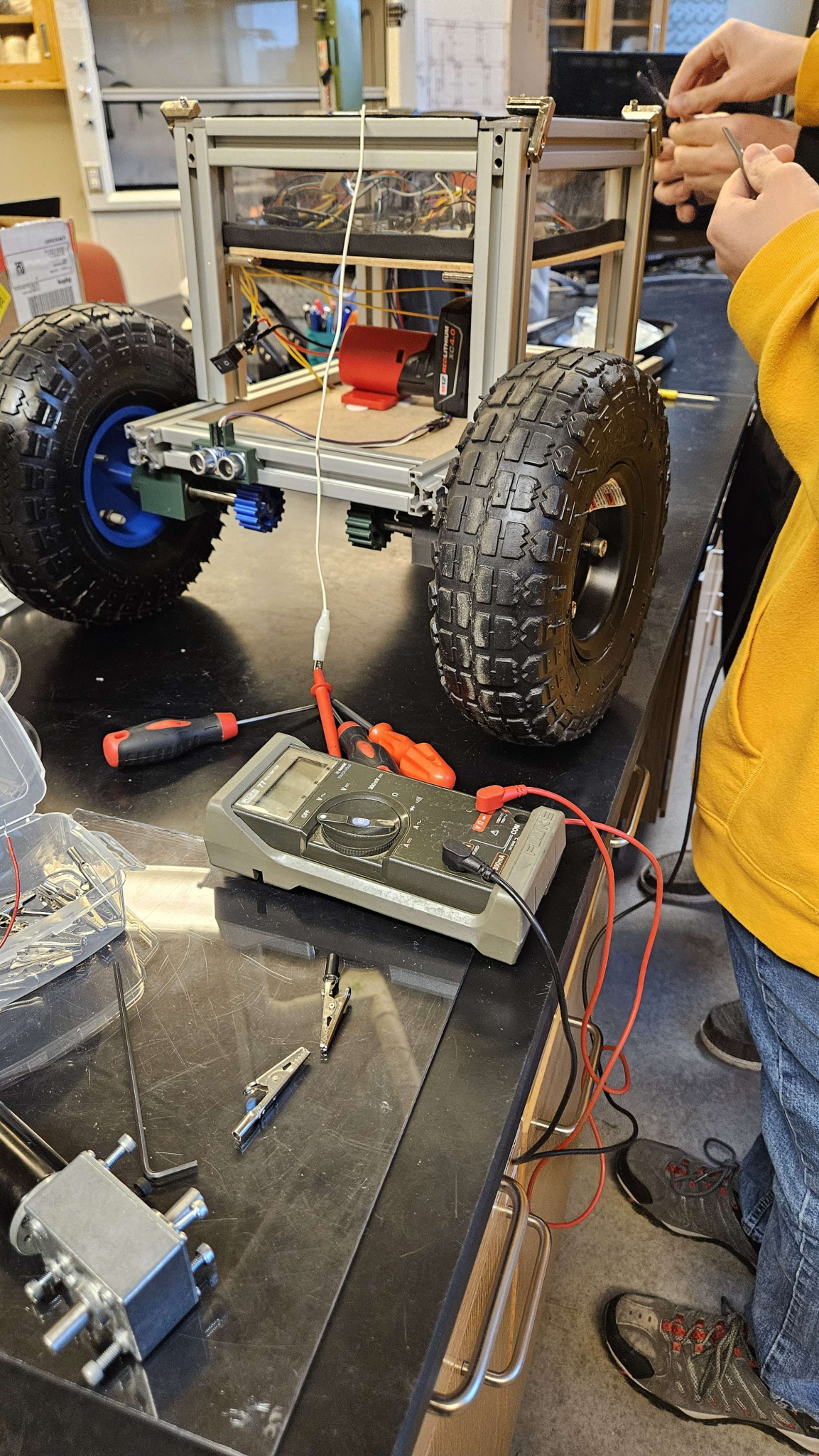
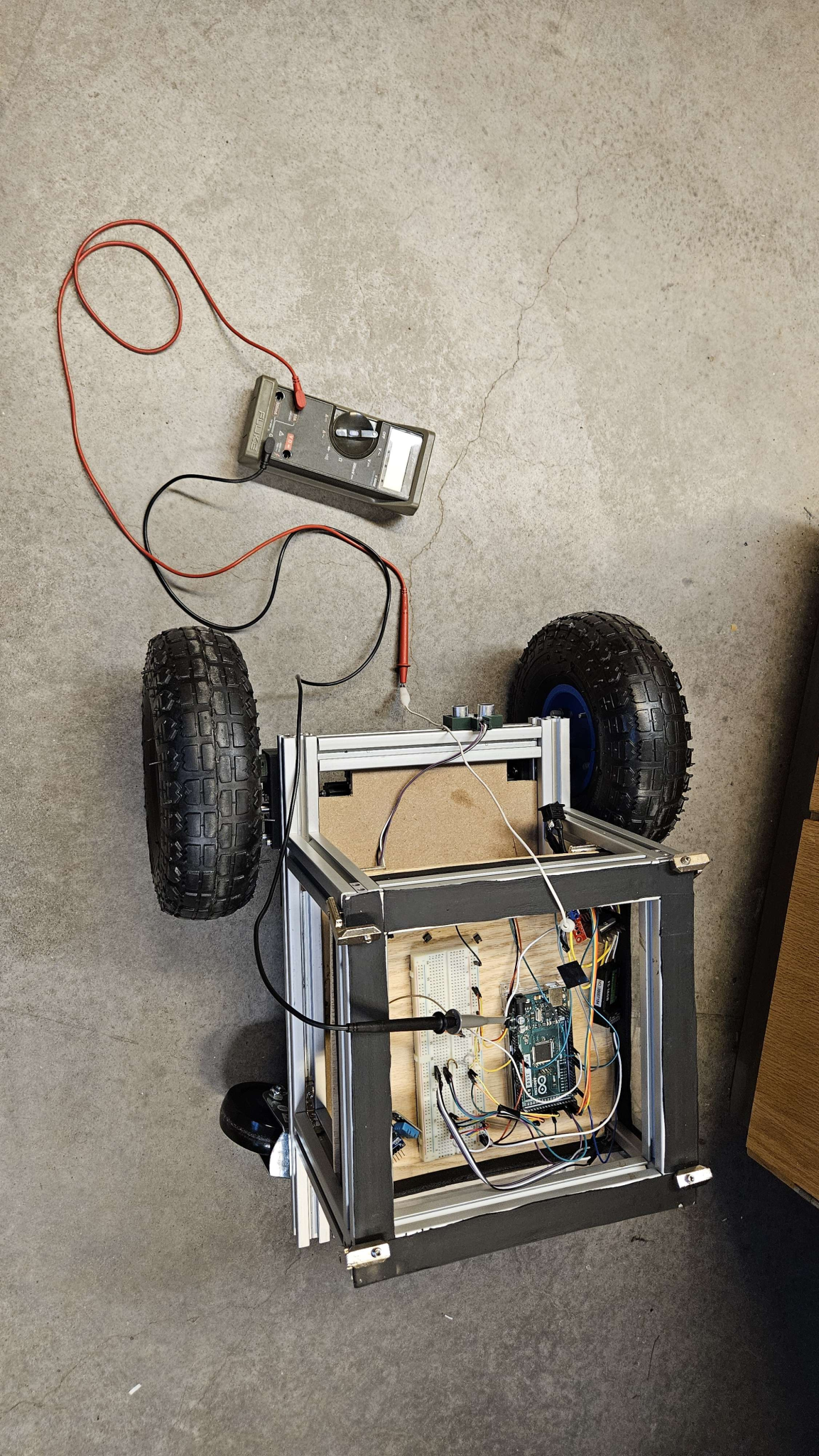
- To investigate this further, we took at look at the receiver itself. One of the pins on the receiver is likely sending a high or low signal based on whether it detects rcCH6. We located this by grounding the multimeter (V DC|:) on the motor controller and touching the other terminal to each pin on the receiver (making sure not to bridge the gap between pins). Then, we would turn on and off the controller to see if the voltage would change. We eventually located the pin shown in the image below:
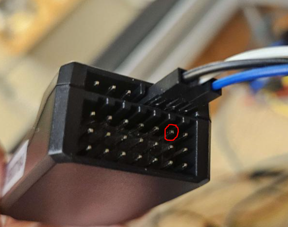
(Note, the middle pin was always 5V.)
- The following comment was haphazardly written into the code:
//10/24/2023: If the controller is disconnected, it keeps whatever motor speed was last and will keep going. This means if you get out of range the robot will run away // Possible fix: Attach a pin to the receiver that feeds information about SIGNAL to arduino. When the controller disconnects, the ANALOG signal should go to zero, so // connect one of those pins to Analog in (A1-whatever), and use that to see whether it should be in autonomous mode or not. (2nd from right, top pin) (ranges from .3 to .16) // .16 is when Ch6 is Low (physically) .3 is when Ch is High (physically). When it’s OFF it just stays in whatever it was before.
- Translation: The voltage on the circled pin is related to the connection of rcCH6, which we are interpreting as the state of controller. When rcCH6 is PHYSICALLY turned down with the knob, it has a 0.16 volts. When rcCH6 is PHYSICALLY turned up with the knob, it was 0.3 volts. Ideally, when the controller is disconnected (losing battery, turning off, moving out of range,) the pin should become low once more. However, we found that if the receiver loses connection with the controller, this pin keeps whatever value it last had.
- Imagine if you are driving the robot at full speed, and then it moves out of range of the controller. The receiver will keep sending the “full speed” signal it last had even if it has lost connection with the controller and your robot will run away!
ONE LAST ISSUE: RC mode does not properly enable and allow the controller to run the motor if the arduino is not connected to the PC! I suspect that this means the arduino does not receive enough power on its own from the battery, and is using the power supplied from the PC. (I could be entirely wrong, but it’s another issue to think about.)
Ultimately, we fixed the motor issue, tested the motors, got the RC mode working again, and learned a lot about how this receiver works, and it is likely a good idea to re-think the way we are switching between auto mode and RC mode.
November 4, 2023
This week, I tried to familiarize myself with KiCAD in order to work on the wiring diagram. I watched the following video:
- Making a new project/library
- Creating a symbol with pins and labels
- Adding components to schematic
Learn KiCad #1 – Make a Schematic
- Terminals, connectors
- Common symbols
Just for practice, I created a rough symbol for the Arduino MEGA.
- Reference: Arduino MEGA Datasheet
- For now, all of the pins are labelled “Inputs” – this is not true, and the appropriate setting should be configured later.
- The size is not accurate. I could not find a way to add dimensions (specified in the datasheet) to a drawing. So, this is not to scale, and merely a representation of what pins are avaliable.
- I am unsure how to cleanly represent the bottom row. Maybe a “long” bottom row instead of doubling up would make sense.
- Symbols for motors, batteries, and switches are already avaliable.
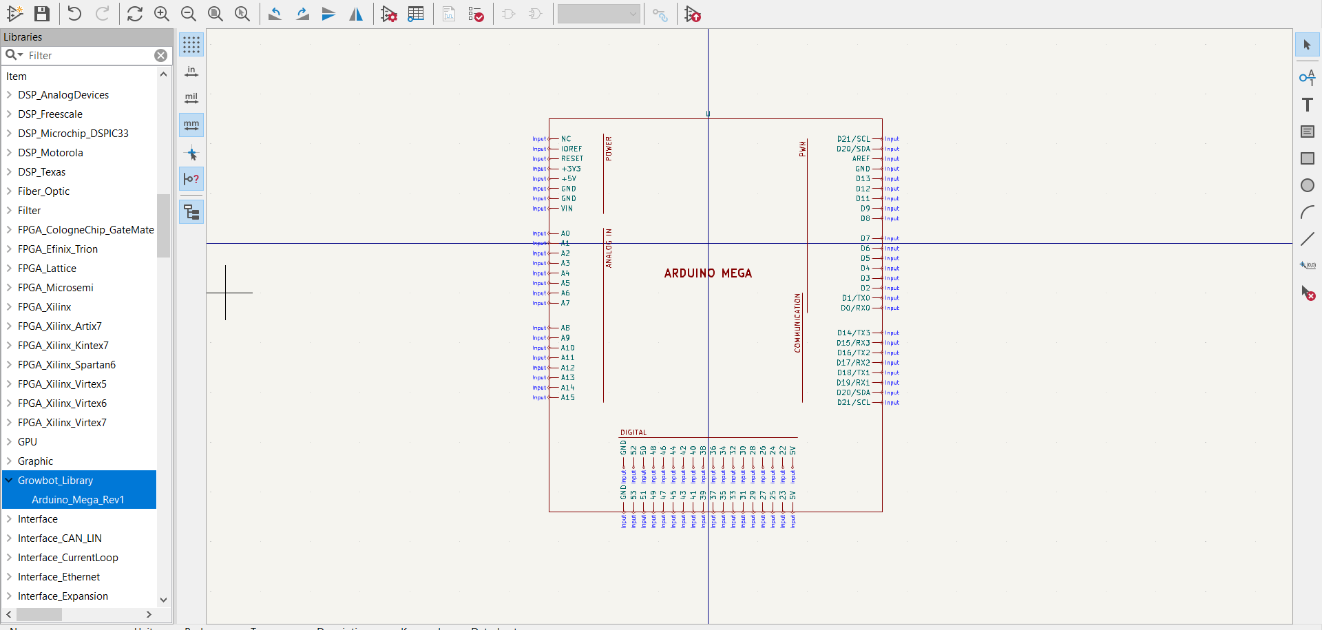
KiCad window for creating symbols.
For the wiring diagram itself, I will need to make symbols for the following components:
- Motor controller (L28N)
- Flysky Receiver (FS – iA6B) – Can’t find a pinout online
For improving the Arduino MEGA symbol:
- Smaller/more compact
- No double rows
In the drive, there is a document called “Wiring Diagram V4” which shows Raspberry Pi, Humidity sensor, and other configurations. If adding these back in the future, this WILL be useful.
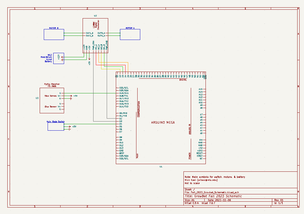
November 6, 2023
The wiring diagram is looking less empty, but many components are just simple boxes, namely the 12V battery, the motors, and the Auto Mode switch, and no sensors are accounted for. As it stands, all of the pins needed to make the robot driver are drawn. However, the power switch is missing.
- Re-organized bottom pins on Ardino MEGA
- Created L298N Motor controller because I didn’t like how the official one looked
- Created FlySky Receiver
- Added temporary symbols for battery, Motors A and B, and the auto mode switch (all seen in blue)
- Need to add power switch between motor controller and battery
- Need to ask about professional conventions for wiring diagrams
November 29, 2023
As the semester is coming to a close, the Growbot team is hard at work ensuring all project specifications are fulfilled in time. We finished printing the back wheel mounts for the new casters, as well as re-printing new front gears, and all four wheels are now attached to the robot. Several test-runs driving the robot around the lab have been met with some success.
- The Arduino is being powered by 5V from the motor controller, less than the needed 7V. Thus, the Arduino’s own 5V output is unstable, and likely causing connection issues with the FlySky receiver. When the Arduino is plugged into a laptop via Ethernet (same as when using the serial monitor) it receives enough power to run normally.
- The robot is not robust enough to drive through unstable ground but it can move forwards, backwards, and turn in both directions within the lab.
- Some of the old 3d printed parts for the front wheels are cracked, which is causing misalignment in the gears and unreliable movement. We are planning on re-printing and replacing these parts.
In addition, an OSF repository has been created for all current documents of the Growbot: https://osf.io/28dq4/
- If anything major is modified, it is possible to create a new Registration of the repository to save previous versions.
The Growbot Project began in 2020 with a generous donation from GM, but with multiple changes in team members and re-definitions of the project, GM has not received sufficient updates on the project. So, on Thursday, November 30, 2023, we will be giving a short presentation at the final MTU Enterprise Manufacturing Initiative (EMI) meeting.
We are continuing to work on our final report, final tests of the robot, and the EMI presentation!
Semester 2: Spring 2024
Thursday, January 25
This week, in addition to working on a finished presentation for the next GM meeting on February 1st, I began to look into how other people online have been working on power distribution. For the presentation, we need to finish a Gantt Chart and a budget.
Links to investigate for RC cars and power distribution:
The first page I found was a person detailing the process of revamping an old RC car.
- They are using the same motor controller board as us. Originally, the RC car used a 12V 1200mA hr lead acid battery. The 12V was used for the camera. To step-down the voltage, a TO3 transistor used as a voltage regulator and the 5V was hacked into the RC control for power. The car was refitted with an Arduino Nano.
- Youtube video following the process from start to finish: https://youtu.be/z8VwoRfqXG0
- Link: https://community.element14.com/challenges-projects/project14/radiocontrol/b/blog/posts/rc-toy-hack—rc-car-rescue-restore-recycle-retrofit
Looking at the image above from the RC car retrofit, the components include a 7.4V Apex Battery, high and a ground rail, all connected to the Arduino Nano, the Qunqi L298N motor controller, and one component I can’t quite identify.
The next page I found shows someone using an ArduPilot board to wire an arducopter.
- Some comments detail different ways to wire. This is an interesting image to study to get an idea how power distribution works for other systems.
- Link: https://diydrones.com/forum/topics/how-to-wire-a-multi-without-a-power-distribution-board-for-idiots
This page involves someone new to Arduino using an UNO and asking about batteries.
- One comment by jremington on April 2022 details “Look at the “C” rating for a battery, e.g. 10C. This is approximately the maximum short term current that the battery can safely deliver, in terms of its capacity C, specified by the manufacturer in Ah or mAh. Example: a 10C battery with C=3600 mAh (3.6 Ah) can supply 36 A, for brief periods. 4.8-6V batteries intended for electric RC vehicles are a popular choice.”
- In addition, jremington states “Search for “arduino external power servo” for many tutorials. Another “gotcha” is that breadboards are designed for low power logic circuits and can’t support high currents for motors and servos. The tracks burn. For many servos, solder power connections, or use a servo power distribution PCB like this one: Servo Power Distribution Board (8 Channel) – goBILDA 2“
- This is a great starting point for transferring our electronics off of a breadboard power distribution system.
- Link: https://forum.arduino.cc/t/batteries-and-micro-servos/978441
Hakeem finally solved the age-old issue of the receiver keeping the last value from the controller when the controller is turned off.
Troubleshooting process:
- Add 5V line and ground to breadboard.
- Plug in the top 5V and GND line to the receiver
- Add a cable to whichever channel you want to observe the signal. This is in the bottom 3 rows of pins. Each “column” corresponds to one channel, and the signal is on the top pin.
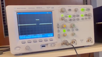
- Hook up one of the signal pins with a cable to the oscilloscope (and ground it on the breadboard)
- This should show up as a square wave that “lengthens” as the controller is manipulated
- When the controller is turned off, the wave should snap to the default state.
If not, on the controller adjust the failsafe settings.
- Turn on the controller
- Long press OK to open menu
- Navigate to “system” with the up and down keys and press OK to select
- Navigate down to RX setup
- Navigate to failsafe
- Select a channel, then use up and down keys to turn it ON
- Do this for all the channels, so they have a percentage next to them
- Long-press “Cancel” to confirm
Now, the oscilloscope will show it snapping back to the “default” position when the controller turns off.
In addition, we noticed that the 5V line from the motor controller to the arduino had come disconnected repeatedy. This wire must be replaced.
Next week’s to-do list:
- Come up with a potential list of components for the robot
- Concerns: We will be presenting these as if they are concrete plans, but it is not finalized at all
- Add components to planned budget
- Organize components by voltage range, to make sure the variety of voltages used on the robot is minimized
- Finish presentation for Thursday
- Send out invites for Thursday presentation
Tuesday, January 30
This week, we had another presentation with our sponsors at GM. We created a Gantt chart to keep us on track. We received a lot of advice.
- Testing – ensure it is quantiative and there are several stages throughout the project
- Power distribution boards – off the shelf boards with built in circuit breaker configurations are likely not cost effective, and it is better to implement cheap automotive fuses
- Safety – The robot should have a killswitch that is easy to reach
Here are some sources for ways other people have assembled their own power distribution system.
- Power distribution systems from Dreamworks RC: https://dreamworksrc.com/product-category/default-category/rc-power-distribution-systems/
- Example of a power distribution box: https://www.reddit.com/r/WLED/comments/yqodvt/my_distribution_box_design_i_hope_this_might_help/
- An RC car electrical diagram (that has issues): https://www.reddit.com/r/arduino/comments/115na1u/rc_car_electrical_diagram_37v_to_5v_step_up/
To do:
- All team members should find various components for power distribution, regardless of how realistic or feasable they are. Next week, we will all meet together and compare components and decide which ones would be realistic to implement.
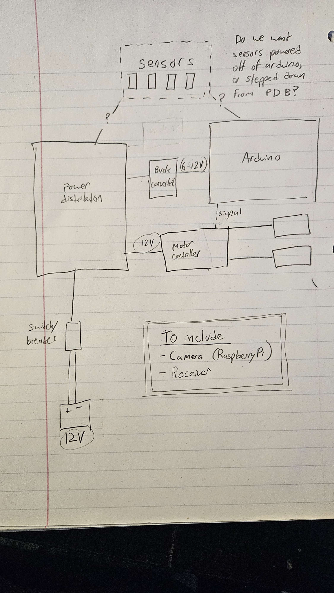
Below is a sketch that was drawn up while we were discussing whether to power sensors off of the Arduino as well as when to step down power. Using a buck converter between sensors and the arduino is a poor idea because it may cause noise, so they will likely be powered by the Arduino’s own 5V line while the arduino is powered by a 7V line.
Wednesday, February 7, 2024
This week, we researched components to add to the upgraded electrical system
Kill Switch – It is important to have a way to immediately turn off the robot, with just the push of a button. Currently, we do have a switch connected directly to the battery, but it is not in the most convenient or reachable location. Thus, having a kill switch in a more accessible location will help with safety. Here are possible kill switches.
- 9.99 Stop Switch Key for Most ATVS and Motorcycles
- 10.99 Handlebar 2 Wire Tether Kill Switch – Intended for 110cc 125cc Taotao Dirt Pit Bike ATV 4 Wheeler Quad Trail Bike
- 20.99 Light Kill Stop Switch – Intended for Polaris, sportsman, magnum, scrambler
- 3.99 Killer RC
- 7.99 LOSI 26CC Mod Kill switch
Distribution board – Overall, power distribution boards are a way to power things at different voltages without using an excessive number of lines. This Forum from 2021 includes an explanation that regulators are needed for each rail with filler capacitors. I think the capacitors are used to avoid using shunt regulators. A diagram that was attached to this explanation is included below. The diodes from the fuse to the output are included for reverse polarity protection. Essentially, all rails are in parallel from the 12V source, and the regulators are keeping the lines at the voltage needed.
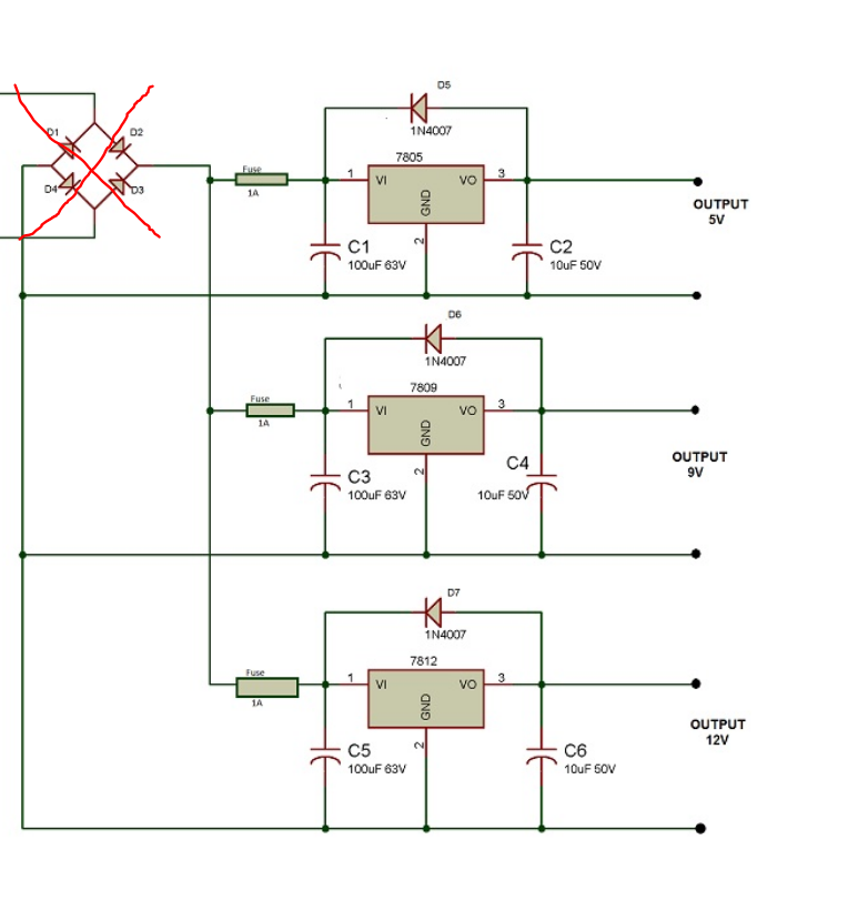
They explained that the diodes should be ignored, and instead 12VDC should be plugged in at that location.
For our power distribution, it would make much more sense to use an off-the-shelf power distribution system. We need something that already has regulators included, or a way to adjust them: 12V for motors, 5V for many sensors (including the raspberry pi), and then ~7V+ for the Arduino MEGA.
- No regulators (just rails)
- 4.59 Holybro 6 output lines
- 13.99 PCB005 10 output lines
- 8.99 Tnisesm 13 output lines
- Regulators
- 9.99 Dorhea (Very little documentation, so probably not)
- 16.99 DROK buck converter
- 11.99 iGreely 12-5V converter
- 3.00-6.00+ depending on current Recom regulator (Lots of documentation)
- How would we wire these?
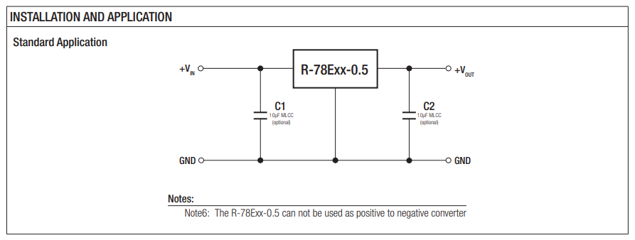
- Example datasheet: https://www.mouser.com/datasheet/2/468/R_78E_0_5-1711129.pdf
- Need to include capacitors? -> We probably have some in the lab
Fuses
- Fuse tutorial
- Calculating what fuses you need: Write down maximum peak power for all devices and use the voltage powering them to get current I=P/V. Then, sum up all currents.
- Fuse each voltage rail
- They are stupid cheap, there are probably some in the lab (ask)
- 8.99 96 fuses from amazon
- Physically connecting fuses:
- 11.00 12 Fuse taps
- Is this only for cars? Easier way to add fuses?
From my understanding, we will have…
- Battery > Killswitch > Fuse > 12V rail
From the 12v rail, there will be 2 rails of
- Fuse > regulator/buck converter > another rail
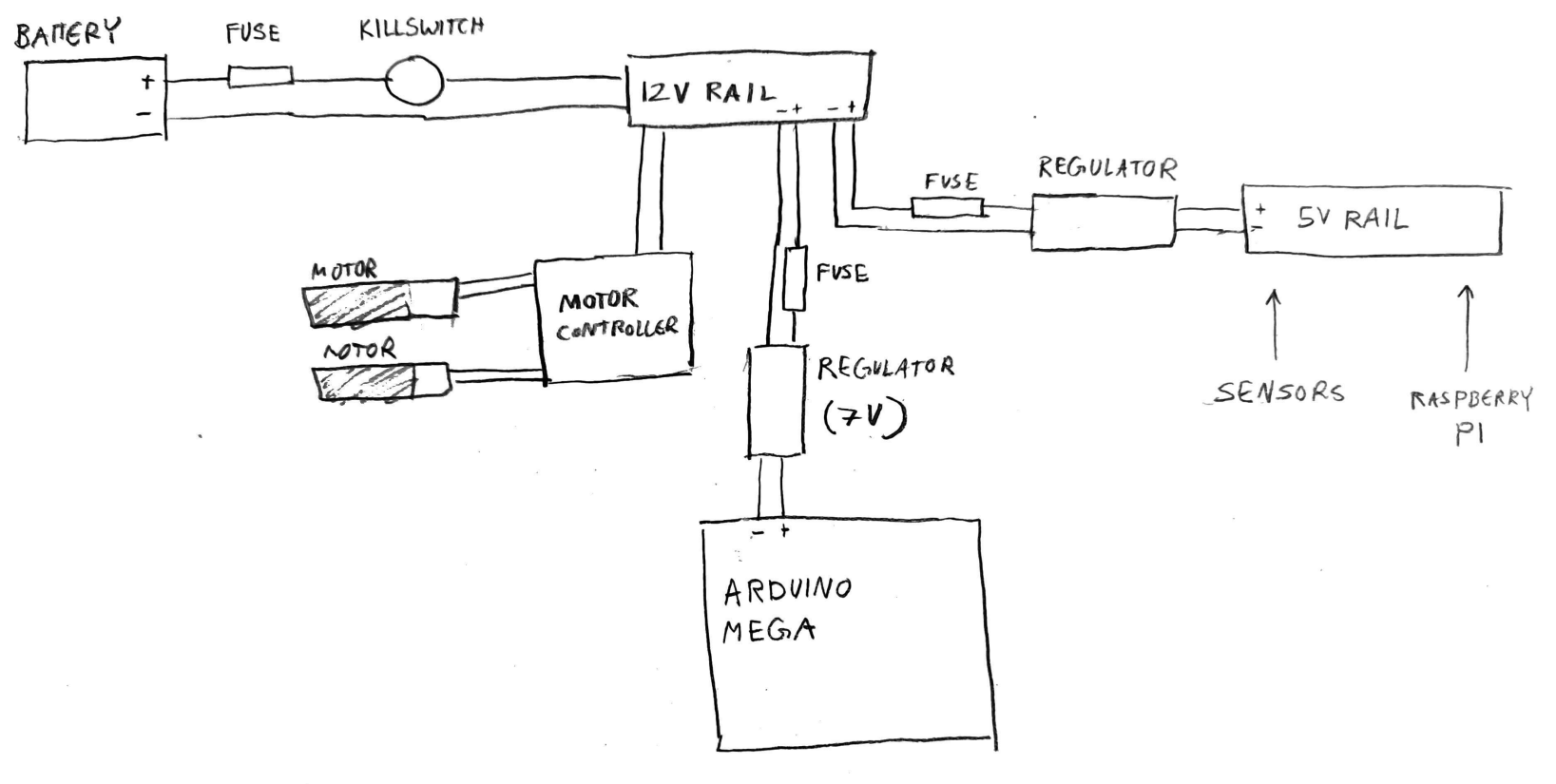
Should we run the 5v rail off of the Arduino Mega?
February 11, 2024
Today, the job was to find the current needed for each of the fuses on the line.
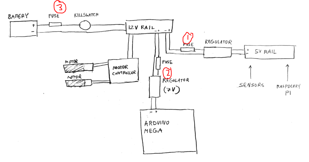
Fuse 1: 15mA
- All sensors on 5V line, including the DHT 11 Humidity Sensor (2.5mA max current), HiLetgo HC-SR04 Ultrasonic (<2mA current), FS IA6B Flysky Receiver (10mA max current). The diagram includes the Raspberry Pi 3 Model B, but this is powered by a Micro USB socket, at max 2.5A. So, it would not be connected to the rail.
- Total value = 2.5m + 2m + 10m = 14.5mA, rounded up to 15mA.
Fuse 2: 400mA
- This is exclusively for the Arduino MEGA. The mega itself uses 50mA. If it is powering anything on peripherals, their current draw will be included too. Currently, the Arduino MEGA serves as communication between the motor controller, sensors, and the receiver.
- If the MEGA is being powered by 7V, and the 5V line is being used to power anything, we want the maximum power to not exceed 1 Watt. Many people recommend not using more than 400mA to avoid overheating.
Fuse 3: 14A
- This fuse is for the entire electrical system, connected directly to the battery. This will require combining the current drawn from all components. The only components not accounted for are the motors themselves, which will be running off of the 12V rail. The motors are “634JSX‑31ZY Motor and Gearbox” with a rated current of 1.6A and a stall current of 6.5A.
- Currently, we have 2 motors. So, if both are stalling, it would draw 13A. We do not want this to blow the fuse, and we also want to account for the smaller added currents from other components, so this can be rounded up to 14A.
Fuse 3 seems too high. So, we will be measuring actual current draw of the motors next time.
Wednesday, February 14, 2023
Today, Eric and Nasi replaced the wood in the electrical box with plexiglass.
We tested the current draw of our motor and gearbox on its own. This yielded about 0.25A.
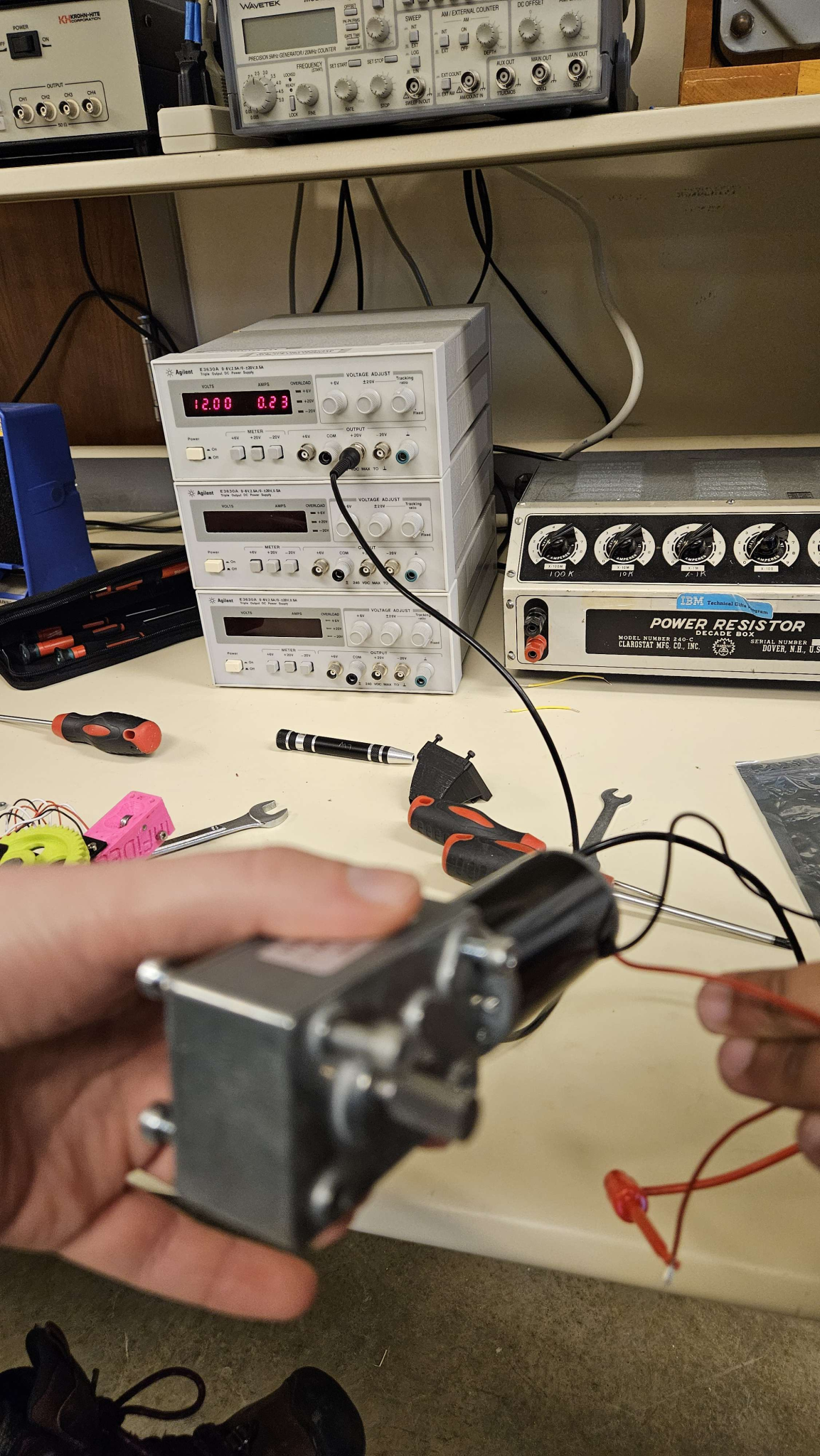
Then, we tested the current while it was driving. This was done by connecting a multimeter in-line between the motor and the motor controller, using somewhat haphazard means.
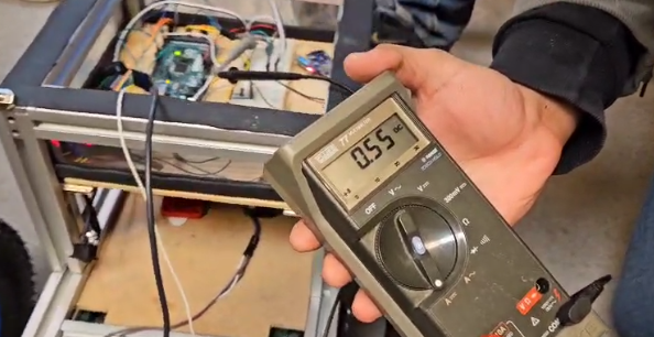
While it was driving, the current would reach 0.61A. All things considered, this was much lower than predicted.
With 2 motors and giving some more “space,” we could use a 2A or 3A fuse for the 12V line.
The sensors all displayed extremely small currents.
The flysky receiver did not go any higher than 0.12A, even when connected to the controller.
The humidity sensor barely reached 0.01A. The specs on the Ultrasonic sensor list they
NOTE:
- Fuses should be AFTER Regulators on the diagram
- We need to test the current drawn by the regulators themselves.
To do: Finish critical design review presentation
Monday, 19 February, 2024
Today, I downloaded QCad to make a to-scale version of our distribution system.
- Here is a video for beginners that I followed
- QCad is remarkably similar to AutoCAD, which is a relief as it is the 2D CAD software I have the most experience with.
In addition, I ordered the following parts:
We also presented our Critical Design Review on Thursday and received a lot of important feeback.
- Test the current draw from the motors again: In more rough conditions, looking for peaks or spikes, and the “stall” current when the shaft is being stopped forcefully.
- Consider using “slow-blow fuses” to account for peaks.
- Consider what fuses to use for sensors
- Look at the documentation for sensors to make sure that the current does not EXCEED the max current.
- When would a high current happen? Either from a degrading sensor that would have to be replaced anyway, or a short. In this case, fuses do not have to be as precise.
- Relays are the only way to implement killswitches. Look into how to do this for sure.
- Check the current rating of the battery.
- Simulation can be performed in Multisim as long as the images and documentation is avaliable.
Thursday, March 7, 2024
More parts were ordered:
- 12 line fuse block – This will be the first area of distribution, our 12V line. This allows fuses to be easily replaced, and even accounting for 4 motors and 1 branching 5v line, still leaves plenty of space for future implementation.
- Relay – This is the way we will implement our killswitch into the circuit.
We discussed our plans for capstone – Likely, we will spend the first semester working on the drive train, and the second semester working on an end effector or navigation system.

This meeting, we also more rigorously tested the current on our motors. We found that the robot struggled greatly to maneuver over an incline. It likely needs new motors, 4 wheel drive, and no casters.
We found that an individual motor could peak over 1A each, so a 2A fuse is likely too low.
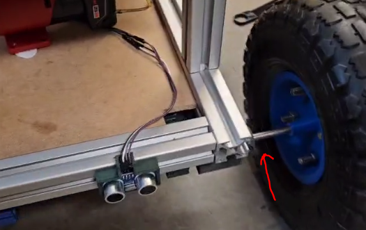
Finally, we found that the shaft for the motor was spinning inside the wheel hub, and we need to find a solution to prevent this.
To do:
- Create GM Presentation
- Finish to scale QLab drawing
Friday, March 15, 2024
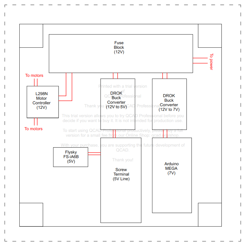
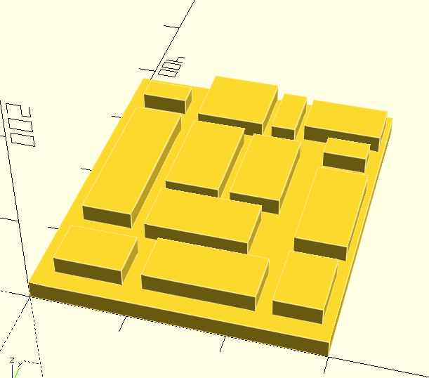
This tuesday, I finished the electrical box diagram showing all the components to scale. The red lines indicate power lines, but are not indicative of the actual wiring.
In addition, we finished our GM presentation and presented to GM. They gave us a lot of valuable advice.
- For planning next semester, create a mock gantt chart to what tasks we think will actually happen. If this becomes hard to plan, it is possible our scope is too large and we need to narrow it down. This should happen as soon as possible.
- We should create a more specific/localized BOM, one document including ALL current parts on the robot including screws, bolts, etc.
- For issues with the motors/drive shaft, there were several suggestions
- Set screw in wheel base to stop axle from slipping
- Drill into the hubs to add a pin
To do:
- Create gantt chart for next semester
- Assemble board once parts arrive on Monday
Wednesday, March 20, 2024
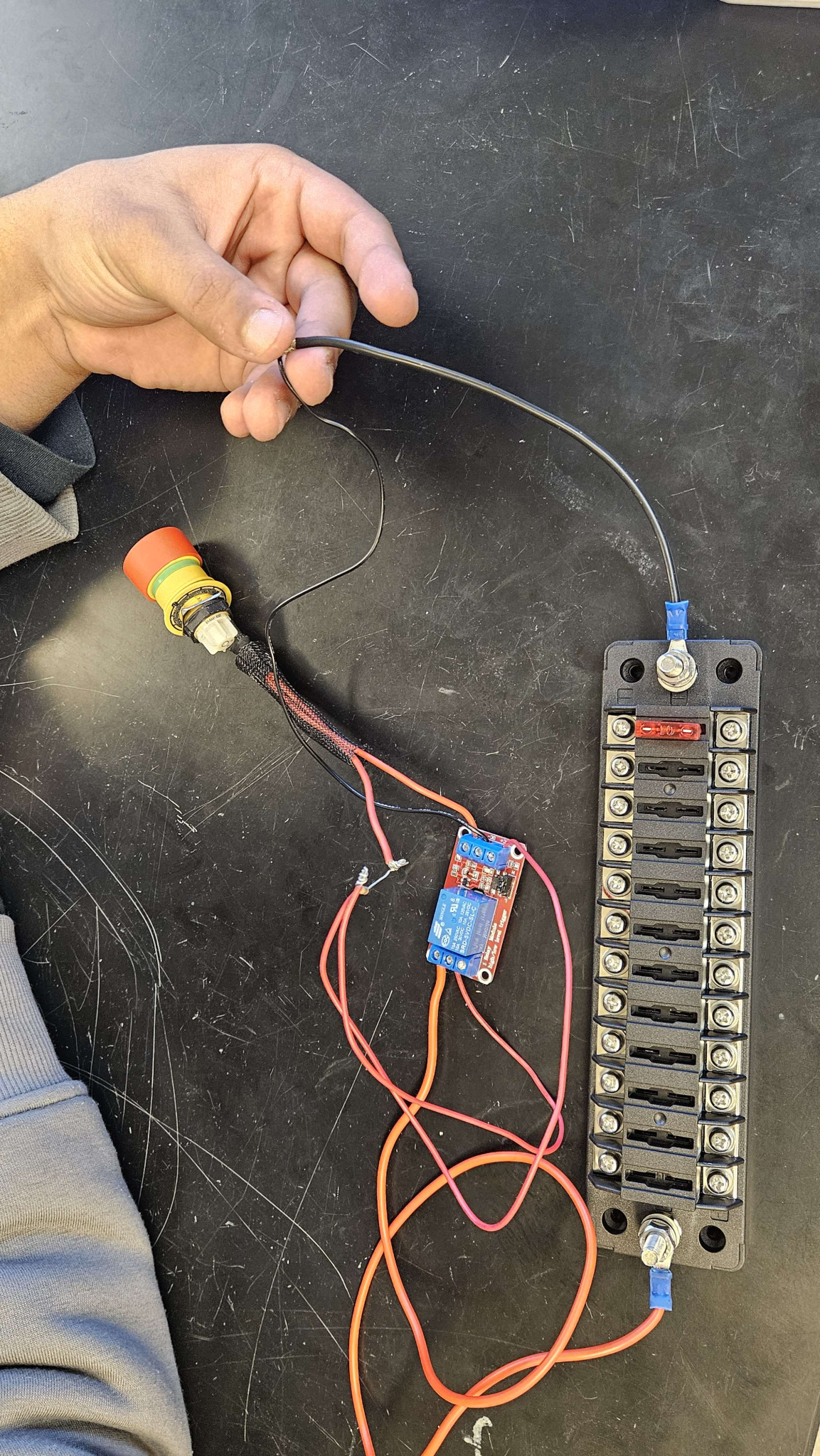
- Our Relay arrived, but not our Fuse Block.
- We took final images of the design to ensure we have full documentation of all connections, in addition to the wiring diagram.
- We investigated how to wire the relay, and found the following resources:
- (Resources will be here soon hold on lol)
- We contacted the electrical lead, Ben Keppers for help. He gave us advice regarding adding a pull-down resistor and general advice wiring a relay.
- Finally, we compiled steps required to improve the drive train next semester.
Thursday, March 21, 2024
- Our fuse block arrived.
- Wiring
- We attempted multiple wiring combinations of the fuse block, killswitch, and relay, using a DC power supply supplying 5V as our “Battery.” We stripped wires, crimped connectors to connect directly to devices, and left wires bare where they would connect to the DC power supply, where they would be held together with the alligator clips.
- Possibly wrong information: We used mostly 18AWG and 20 AWG wire.
- Shoutout to Nasi for wiring everything very quickly and switching connections as needed.
- Testing
- This was tested by placing a fuse in one row of the fuse block and measuring the voltage across it with the multimeter.
- Then, the killswitch would be pressed, then unpressed. Ideally, the voltage across the ports in the fuse block would be 5V when the killswitch was not pressed, and 0V when the killswitch was pressed.
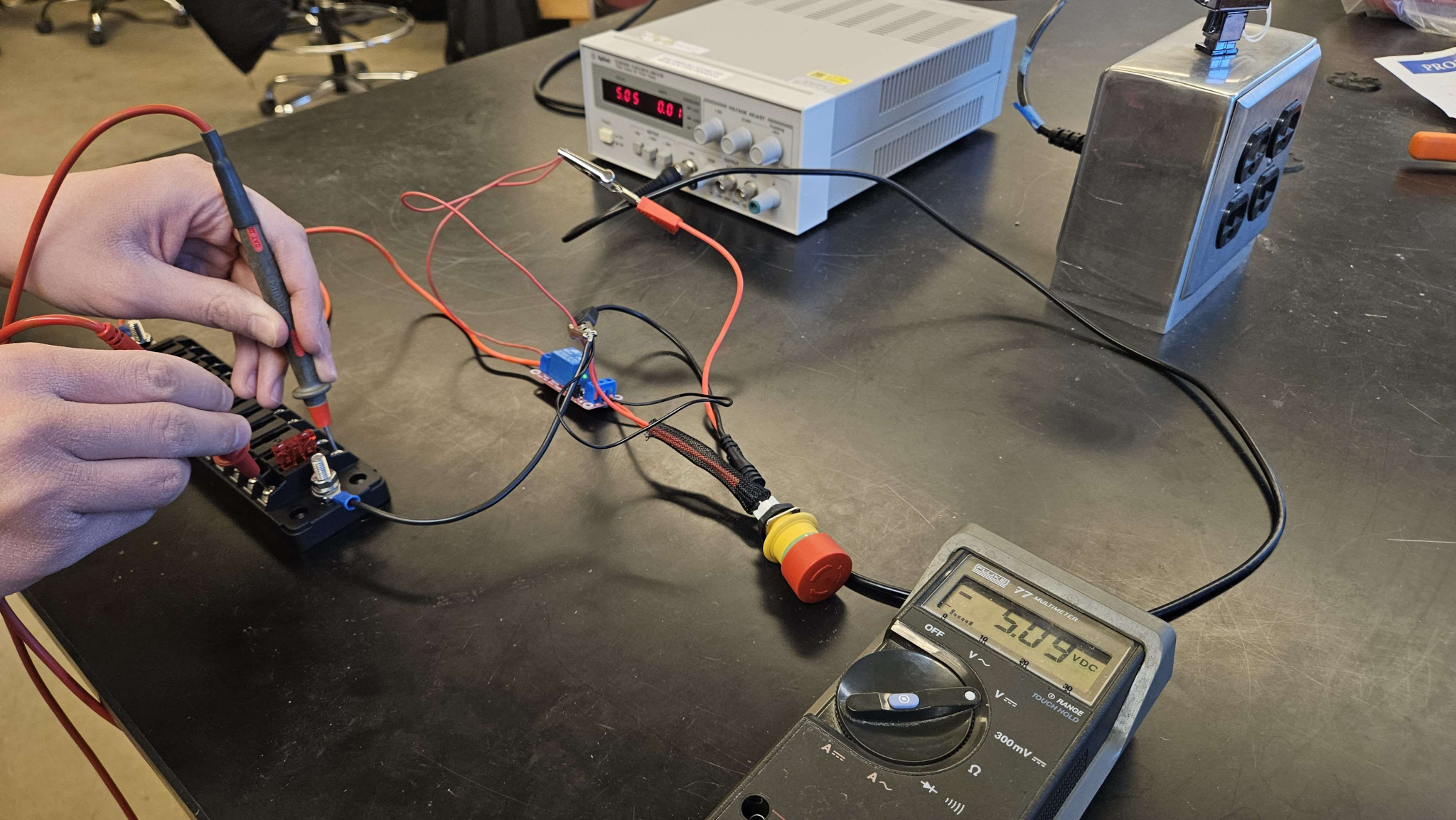
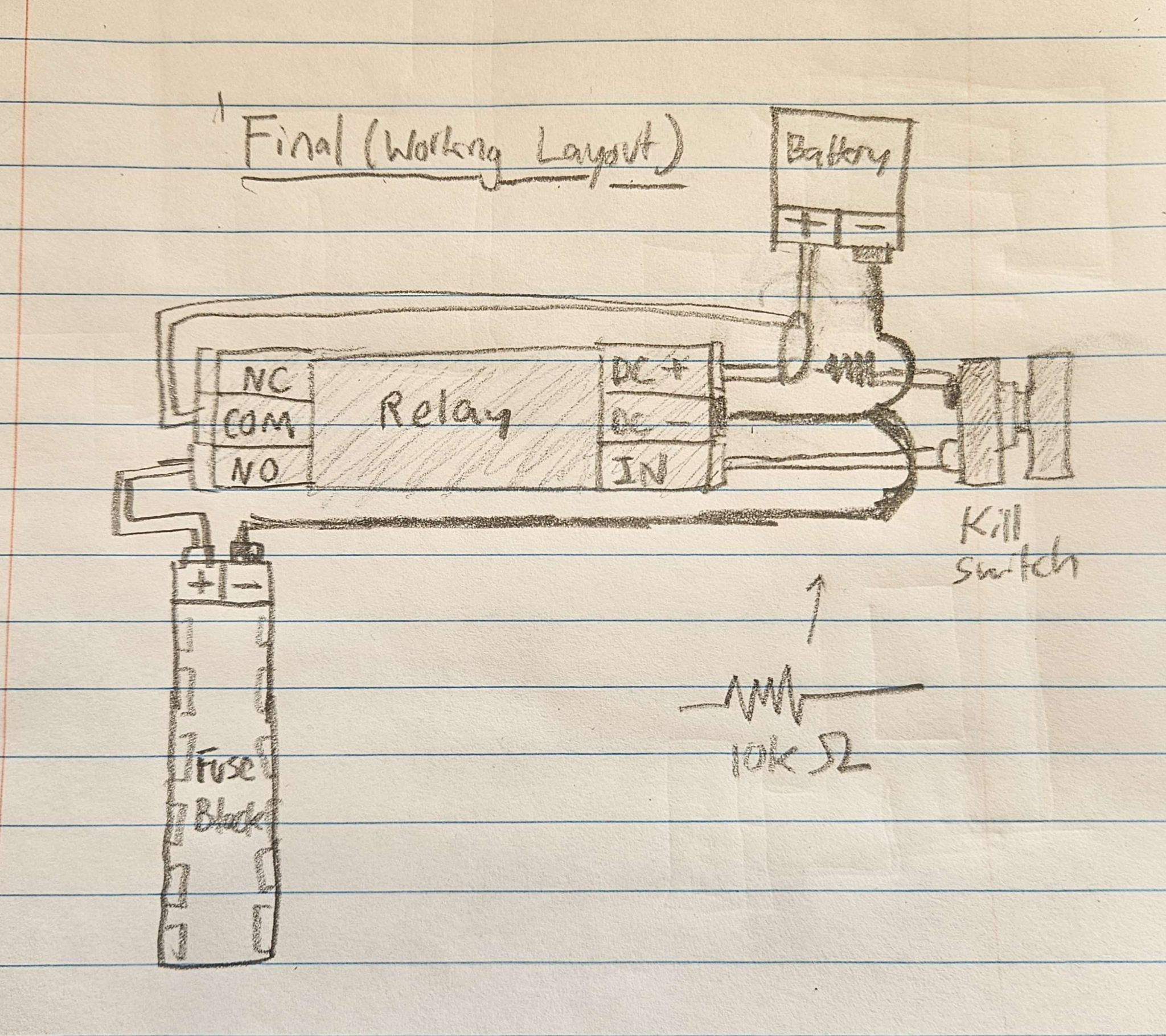
- This was the final design that ended up working (below)
- I’d like to thank Hakeem for getting the resistor in the right combination and James for the moral support.
To do:
- Continue connecting components and placing them in the electrical box
- Creating the March 28 Presentation for GM
Thursday, March 28, 2024
This week, we continued with assembly.
After writing down all the Arduino MEGA connections, we detached all components from the electrical box: The breadboard, the arduino, the motor controller, the FlySky receiver, and all sensors. Then, we secured two buck converters to the Fuse block. One buck converter was wired the Arduino MEGA, and the other was wired to a power rail. The FlySky receiver was then attached to the power rail.
- The gauge of the wire used depended entirely on the kind of connectors that would be secured to the devices. It is possible we may need to modify it later.
- We used a 1A fuse for both the Arduino and the 5V power rail. We are planning on using a higher amperage fuse for the motor controller.
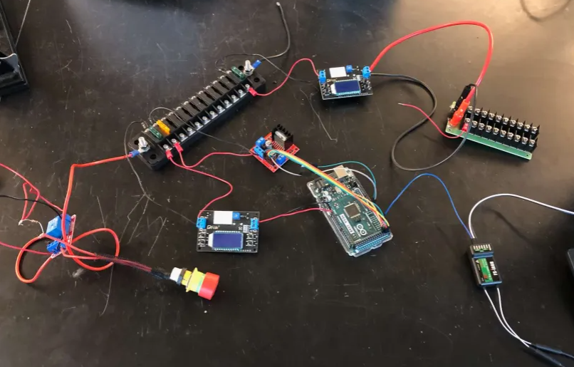
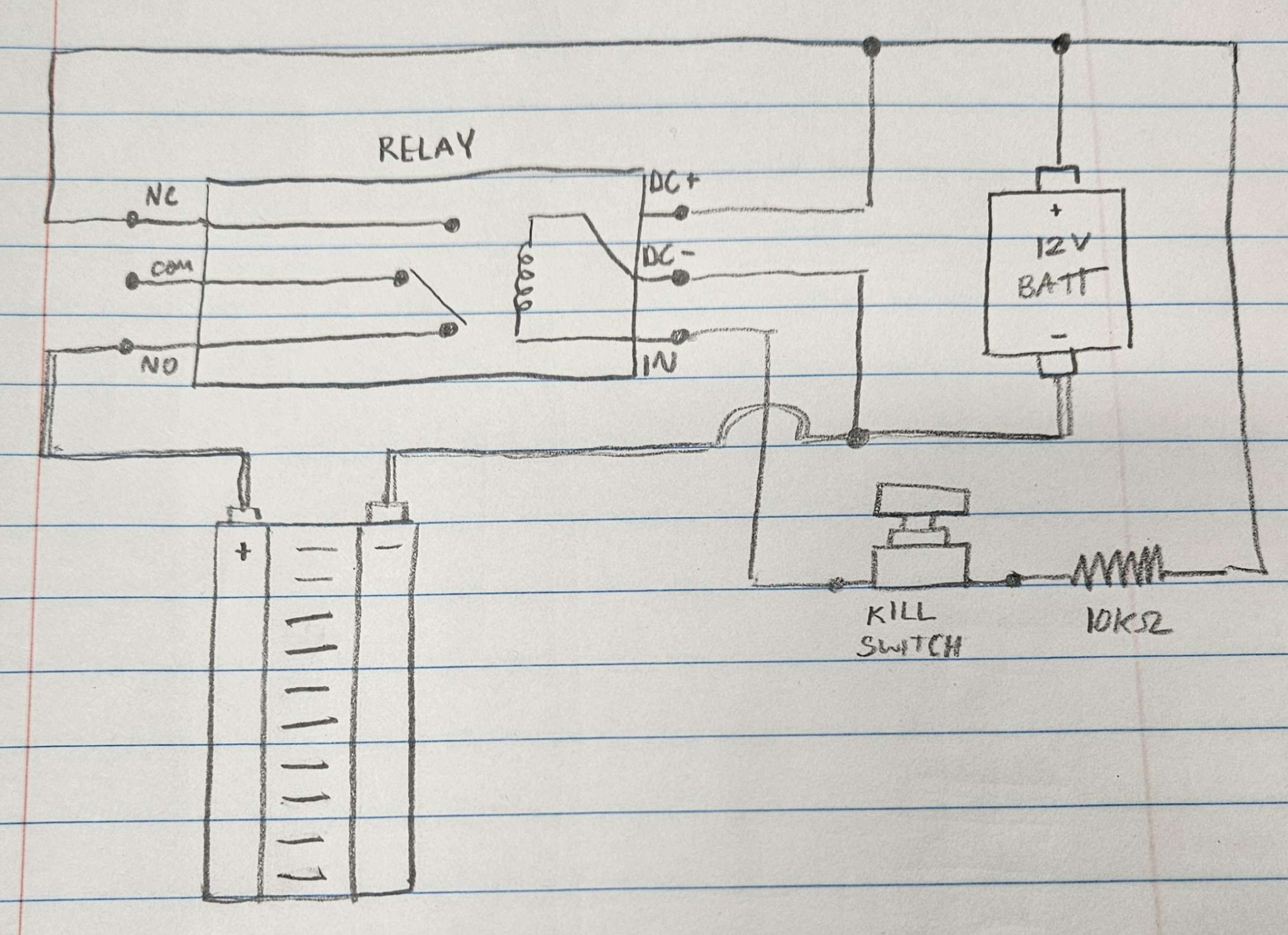
- A wiring diagram for the relay was sketched out based on the working configuration.
Currently, all wires and leads are very long. We will have to shorten them to organize better and fit them in the electrical box efficiently.
After our meeting with GM today, we got some advice regarding cable management and wiring.
Then, we tested the distribution system with a DC power supply and setup the buck converters. The FlySky controller and receiver would sucessfully connect, and the oscilloscope revealed it was transmitting the correct signal. In addition, we built the mounting covers onto the buck converter.
Below is an image of the buck converter cover and all components laid out on top of a cover the size of our electrical box.
Wednesday, April 3, 2024.
We submitted our project proposal for the Fall 2024 and Spring 2025 semester. We began writing our rough draft for our project report. We came up with ideas on what to say in a social media video.
In addition, we removed the yellow cables for the motors and Nasi soldered longer black and red cables onto them for ease of moving. We helped Eric drill a hole into a plastic cover for mounting the killswitch.
Next time, we will wire the motors to the motor controller and connect the motor controller to the 12 fuse block line.
Thursday, April 4, 2024.
- We recorded videos for our social media post
- We finished our initial draft for the final report
- We wired the motor controller, battery, relay, and motors together
- We tested the robot: The arduino is now self sufficient, and the robot is able to power itself. The switch turns power on and off, the killswitch immediately cuts all power when pressed.
Monday, April 8, 2024
Today, the team met briefly to plan for the project Check Off. We created our presentation for GM this week, and confirmed which motor on the Growbot was experiencing issues. We noticed the following:
- The motors were wired backwards: That is, the robot drives in the reverse direction as input on the controller (forward/backwards).
- The right motor does not engage when the backward motion is input into the controller.
In addition, one of the motor housings cracked, so we re-printed it and have plans to secure it tomorrow.
Tuesday, April 9, 2024
The team performed a project Check-off. We received the following feedback:
- Next semester, the drive train should be updated completely
- The following semester, we must decide on one of the following paths for the robot
- Further sensor integration
- Autonomous navigation
- A winch/connector for tilling, water distribution, some kind of platform to further expand functionality
In addition, we found that the wiring between the Arduino MEGA and the motor controller was causing the driving issues from yesterday. It was rectified and the robot now operates as expected.
Thursday, April 11, 2024
Today, we met with our GM sponsors once again. We received the following feedback:
- Design Requirements
- Waterproof? – Remove all electronics and test on the robot
- More advanced text matrix for terrain, repeatable
- Define “dirty” and whether robot can operate in those conditions
- If there are failures, plan which direction to turn in
- Do testing halfway through (week 9ish?)
- Enough funding for both semesters of capstone?
- Probably enough for first semester
- Need to make decision for second semester
- If there is an issue (cracking housing) what are you doing to ensure it doesn’t happen again – Printing in a different orientation to prevent propogation and using denser infill for strength.
- Autonomous program can be simple
Advice from Drew
- Look for an oldDecision matrices around the motors: Fall 2019, Spring 2020
- 1 year after this, there was a working autonomous
- ROS done on Raspberry PI in previous year
- Send the social media video and final report to GM once it has been completed.
To do:
- Submit updated capstone proposal
- Continue working on final draft of report, considering peer review feedback
- Once capstone proposal is approved, register for classes.
Saturday, April 13, 2024
Today, I updated the OSF repository with the new KiCAD file and a new QCAD file.
We continued working on the draft for the final report, and we continued developing our plans for the capstone proposal and submitted it.
Thursday, April 18, 2024
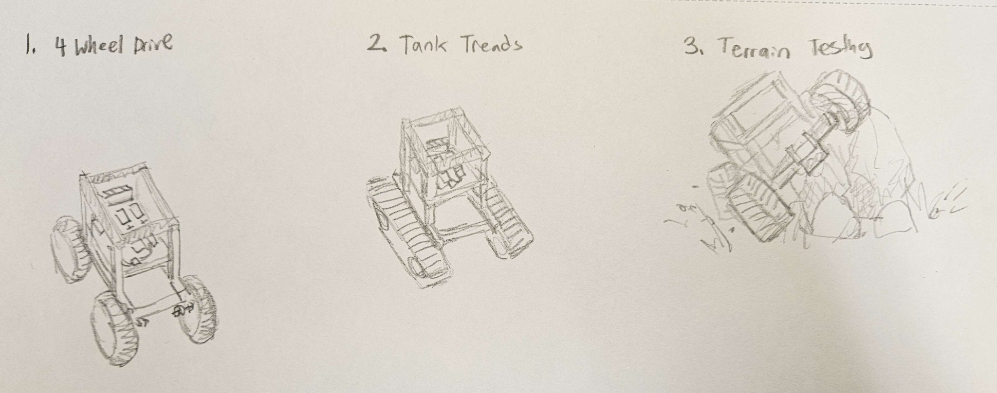
To wrap up the semester, we took into consideration the feedback given in the peer reviews over the past few weeks, and using it we finished our Final Report. In addition, we made our new OSF repository pages public. We discussed the directions for next semester. More specifically…
- We decided to go with a 4-wheel design for the drive train next semester
- We discussed having more specific and outlined roles for everyone on the team so it is very clear what everyone contributed to the team
- We want to have our decision making done as soon as possible so we can immediately begin ordering parts and begin testing halfway through the semester.
The individuals at GM graciously gave us permission to add their names to our report in the Acknowledgements section.
Overall, this semester was a great learning experience, and we managed to complete all of our goals. It has been truly exciting seeing everything come together and have the robot be able to power itself independently. It was quite a challenge to figure out the design for the relay, but seeing it work was very satisfying. The team is feeling very confident about the direction of the project and we are excited to continue working on it for our Capstone next semester.
Semester 3: Fall 2024
For this semester, we will be splitting into groups to work on different parts of a cleaning robot built around a shop vac. Here are some sources about the different systems we will need.
Feeder for cleaning solution
- Spray mechanism?
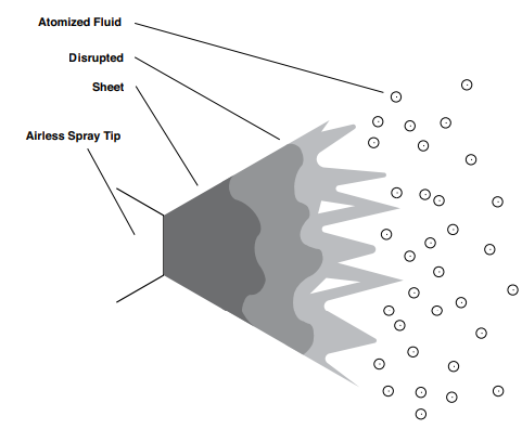
- Airless spray: https://www.graco.com/content/dam/graco/ced/literature/misc/321132/321132EN-H.pdf
- “In airless spray, the fast moving high-pressure liquid stream provides the energy necessary to overcome the fluid’s viscosity (resistance to flow) and surface tension (a force that bonds the surface of a liquid together) to form a fine spray. In the depiction of spray from a gun, high pressure forces fluid through a small nozzle (spray tip). The fluid emerges as a solid stream (sheet) at a high speed. When the solid stream hits the air, it becomes disrupted. This disruption breaks the fluid into fragments initially, then ultimately very small droplets that form the spray pattern.”
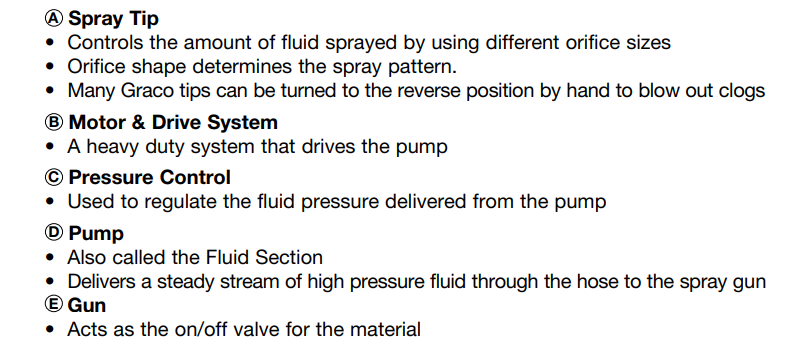
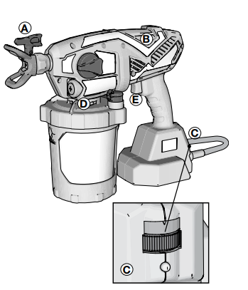
This seems like a quite complex industrial application but just to get some ideas down, I’m also going to paste from that link the information about the components required.
 |  |
- Spray bottles (Source: https://home.howstuffworks.com/question673.htm)
- Trigger lever – activates a small pump.
- Pump – draws cleaning fluid from bottom of the reservoir w/ plastic tube. The pump forces this liquid down a narrow barrel and out a small hole at the gun’s muzzle.
- Nozzle – Hole that serves to focus the flowing liquid so that it forms a concentrated stream.
- “The only complex element in this design is the fluid pump, and it’s about as simple as they come. The main moving element is a piston, housed inside a cylinder. Inside the cylinder, there is a small spring. To operate the pump, you pull the trigger back, pushing the piston into the cylinder. The moving piston compresses the spring, so when you release the trigger, the piston is pushed back out of the cylinder. These two strokes of the piston, into the cylinder and out again, constitute the entire pump cycle.”
Here is a solidworks video to see an animation of this
And here is a video of someone actually assembling a spray bottle
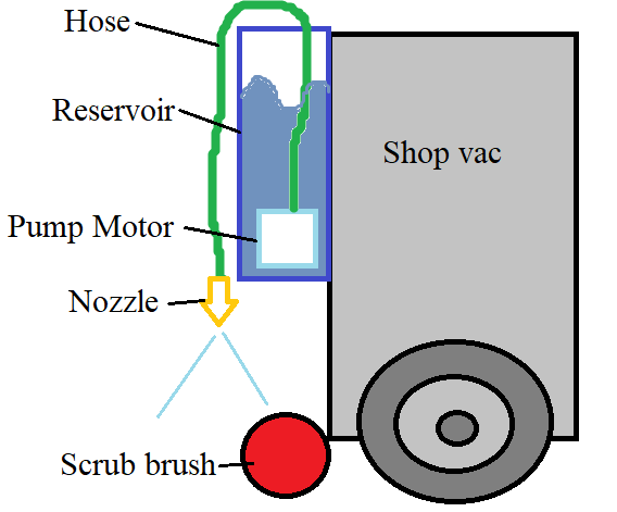
General ideas for a fluid dispensing system: Some kind of spraying mechanism, either on the floor or onto the scrub brushes.
- Need a pump, a motor, a nozzle
- Nozzle design determines how much fluid is dispensed, distance, how fine the mist is, etc. Then, depending on nozzle design, know how strong of a motor/pump is needed
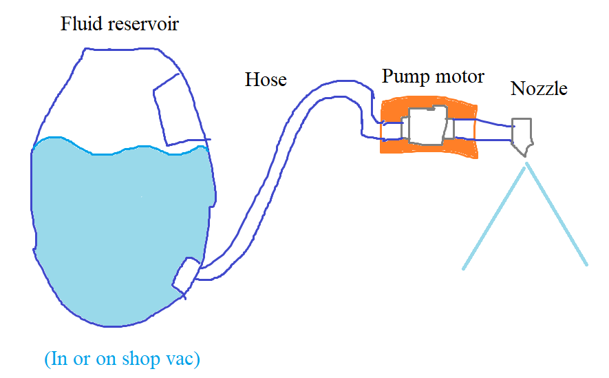
- Pump motors are on the market. Pay attention to “priming” – is the pump in the water, or is it just a tube into the reservoir? Can the pump operate when dry? It is best if the motor is inside the water container, so it does not need to prime itself.
2 options
- Open loop system, sprays every x seconds (using relay)
- Controlled system, using motor controller
Brainstorming
WHAT DO YOU NEED
Requirement before specification (Basically, what do you need to fulfill?)
- Create a spray
- Spray distance – 1 foot
- Spray area – 1×1 square foot
- Spray is variable – Not constantly running
HOW WILL YOU DO IT?
Written design concept (written down)
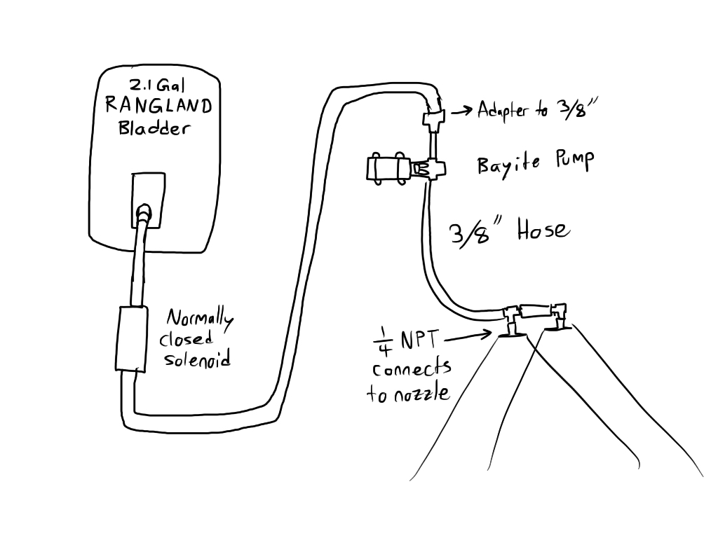
A pump motor is placed in a reservoir of cleaning solution. The hose carries the solution out of the reservoir to the front of the device and feeds into a nozzle, which sprays the scrub brush. The motor is controlled by shutting on and off power with a relay.
- How strong do the motors need to be?
- Can the motor vertically pump water out of the reservoir?
- Is the pressure high enough for the nozzle to spray?
- What current/power does it use?
- Since it activates in short bursts, will it have too heavy of a load on the battery?
- How large of a reservoir do you need?
- Depends on nozzle design and size of scrub brushes.
Drawn design concept
- Sketch of electrical design
- Sketch of mechanical design w/dimensions
- Information to consider:
- Size of packaging
- Size of reservoir
- Location of components
- How they are connected (bolts and stuff, tubes and valves or whatever)
September 4, 2024
Resources for spray nozzle calculations
- https://en.wikipedia.org/wiki/Spray_nozzle
- Basic overview and names of different types of nozzles
- https://www.spray.com/resources/sprayware-calculators-and-tools/flow-rate-calculator/
- This does calculations, but doesn’t show formulas or anything.
- https://www.fs.usda.gov/Internet/FSE_DOCUMENTS/fseprd497001.pdf
- This is for agricultural applications, like those huge irrigation systems with nozzles that are 20 feet apart. So, the formulas don’t always apply.
- https://www.pubs.ext.vt.edu/content/dam/pubs_ext_vt_edu/442/442-032/BSE-262.pdf
- This is again aimed at agricultural applicaitons, but it explains some terminology and spray shapes.
- https://royalbrinkman.com/knowledge-center/crop-protection-disinfection/calculating-required-spray-liquid
- Not super helpful, it basically says look at nozzle tables to tell how much water is dispensed for certain areas.
- https://www.spray-nozzle.co.uk/docs/default-source/default-document-library/whats-in-a-spray.pdf
- VERY GOOD RESOURCE. Explains formulas, inner working of nozzles. Best for design.
- https://www.physicsforums.com/threads/how-do-the-nozzles-on-spray-bottles-work-when-misting.942364/
- https://fogco.com/misting-nozzles-explained/
- Explains size of water droplets
- https://publications.iafss.org/publications/aofst/6/6c-1/view/aofst_6-6c-1.pdf
- Includes formulas and design principles
- https://fogco.com/misting-nozzles-explained/
Potential Pumps
- Non submersible, would have to be outside the tank right where the nozzle is.
- VEVOR (360GPH) (not self priming)
- Example of it being used: https://www.youtube.com/watch?v=16A51XNrWSQ
- Acquaer (264GPH) (self priming)
- VEVOR (360GPH) (not self priming)
- Submersible
- Superior (1800GPH) (Different HP options)
- GROWNEER (550GPH)
- Freesea (330GPH) (400-1200GPH)
- Hiletgo (240GPH) (2 of them)
September 10, 2024
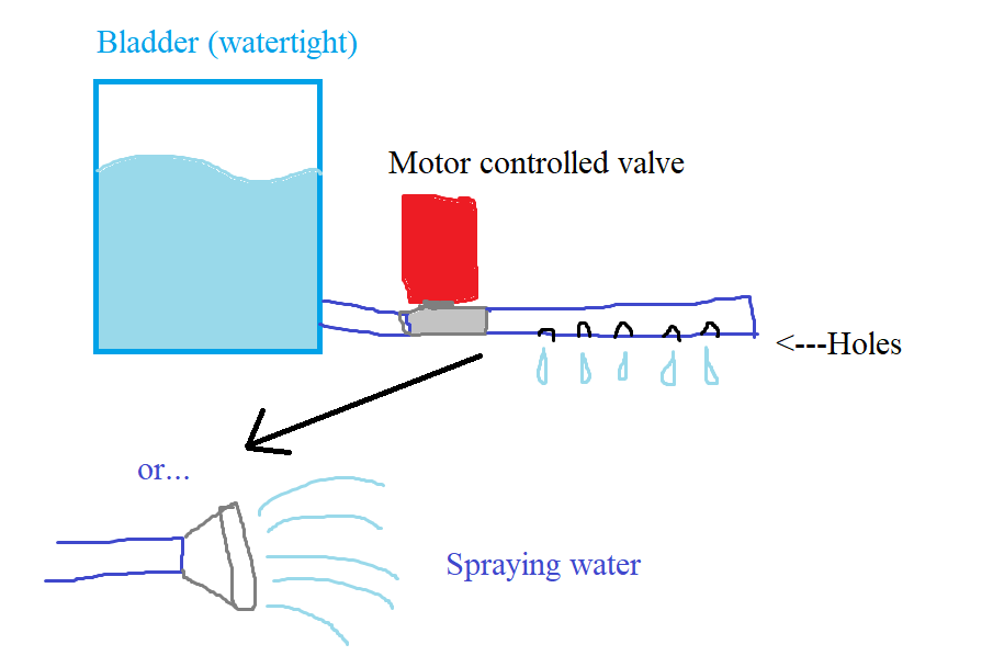
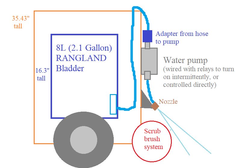
Wesley proposed the idea of a bladder inside the machine to carry water. This would solve so many issues such as things being watertight, but a submersible motor will not work because the cable and hose would have to leave the bladder, and any way of doing this compromises the bladder being watertight.
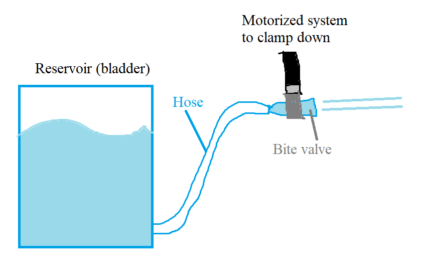
Gravity fed, non-pump idea
Motor pump idea
September 11, 2024
So I’m kinda going in circles about this subsystem.
I looked into different water bladders:
- This one seems the most promising, as it is 8L or almost 2.1 gallons.
The issue with a “gravity fed” system is actually the construction of the bladder. It does not squirt out water, it needs some pressure to pump it out. When someone’s drinking out of the tube, the suction they can create themselves is enough. But just having the tube on the ground is not enough. Maybe we need a hydration bladder AND a pump instead. In that case it is similar to the pump motor version of this design.
Alternatively, reservoirs with “bite” valves can be activated by designing a mechanism to squeeze that is powered by a simple servo motor.
Let’s compare costs for some of these decisions:
Using the bladder ($29.99)
- Non submersible pump motor ($40-60)
- Valve motor ($30-40)
Using flat-bottomed reservoir (bucket, around $10)
- Submersible pump motor ($15-$20)
- Non submersible pump motor ($40-60)
- Valve motor ($30-40)
I ended up finding some more in-line motors
Overall thoughts on specs today:
- Drawing out water requires a pump, “Gravity fed” systems do not spray reliably
- There are affordable (~$25) inline pumps
- Can be controlled with relays
- Need to ensure pump can pump high enough, “total head lift”
- Make sure it has decent flow rate & enough lift
- Bayite water pump has 6.6m lifting height and 1.2 GPM
- 3/8” hose ports
- Kinda loud af
September 12, 2024
Inverter considerations
- Inverter current draw: https://www.mastervolt.com/frequently-asked-questions-about-inverters/
- “How much current will an inverter draw from my batteries?
- This depends on the equipment connected to the inverter. There is a simple method to calculate how much power your inverter is using: For 12-volt inverters, divide the connected load by 10; for 24-volt inverters, divide by 20.
- Example: How much does an inverter consume with a 400 W load connected? For a 12 V inverter such as a Mass Sine 12/1200, consumption will be 400/10 = approx. 40 amps. For a 24 V inverter, say a Mass 24/1500, the corresponding figure is 400/20 = approx. 20 amps. It is important to remember that this is only an approximation: The actual consumption will tend to be some 5 to 15 % less, depending on the load type.”
- Do not mount it vertically, have it horizontal. Point the fan away from electronics, it is blowing out hot air. Do not cover it either. More inverter info = https://www.youtube.com/watch?v=KPjt6GtvcNE&ab_channel=Justin%27sProject
- Our battery is 24V. We could step down to 12VDC to feed the inverter. The inverter must handle 1200W continuous, not sure what the peak of our vaccum is.
- 82.99 DongJin:12V DC to 120V AC (1200W continuous, peak 3000) https://www.amazon.com/DongJin-Power-Inverter-Converter-Vehicles/dp/B0C1N9FWWL?source=ps-sl-shoppingads-lpcontext&ref_=fplfs&smid=AYGOM05UUYR95&th=1
- 1200W load / 10 = 120 amps
- 77.99 VEVOR: 12V DC to 120V AC (1250 continuous, peak 2500) https://www.amazon.com/VEVOR-Converter-Controller-Indicator-Emergency/dp/B09D2ZTWWQ?source=ps-sl-shoppingads-lpcontext&ref_=fplfs&smid=ATVPDKIKX0DER&th=1
- 13.2 x 8.5 x 5.7 inches, 5 pounds
- 1200W load / 10 = 120 amps
- 82.99 DongJin:12V DC to 120V AC (1200W continuous, peak 3000) https://www.amazon.com/DongJin-Power-Inverter-Converter-Vehicles/dp/B0C1N9FWWL?source=ps-sl-shoppingads-lpcontext&ref_=fplfs&smid=AYGOM05UUYR95&th=1
- 24V inverters instead:
- 153.41 Power bright: 24V DC to 110V AC (1500 continuous, peak 3000) https://www.amazon.com/Power-Bright-ML1500-24-1500-Inverter/dp/B000NND5H4?source=ps-sl-shoppingads-lpcontext&ref_=fplfs&psc=1&smid=ATVPDKIKX0DER
- 1200W load / 20 = 60 amps
- 142.22 VEVOR:12V DC to 120V AC (2000 continuous, peak 4000) https://www.amazon.com/VEVOR-Inverter-Converter-Controller-Indicator/dp/B0CR38X35V?source=ps-sl-shoppingads-lpcontext&ref_=fplfs&smid=ATVPDKIKX0DER&th=1
- 1200W load / 20 = 60 amps
- 153.41 Power bright: 24V DC to 110V AC (1500 continuous, peak 3000) https://www.amazon.com/Power-Bright-ML1500-24-1500-Inverter/dp/B000NND5H4?source=ps-sl-shoppingads-lpcontext&ref_=fplfs&psc=1&smid=ATVPDKIKX0DER
FOR THE VACCUUM ALONE: If we are running 120 amps for 10 mins, we’ll need a 20Ah. If we are running 60 amps for 10 minutes, we need 10Ah.
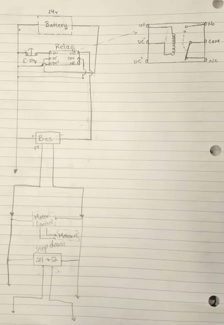
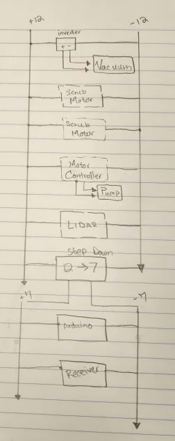
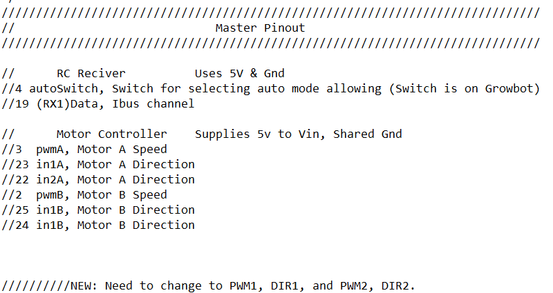
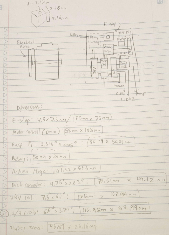
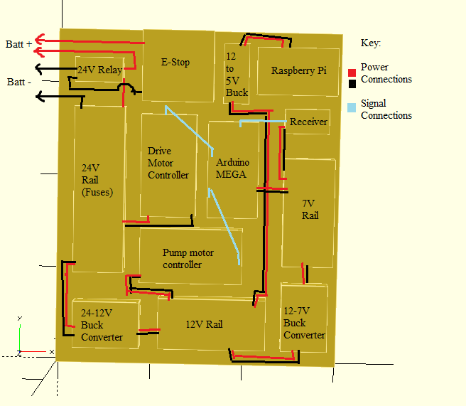
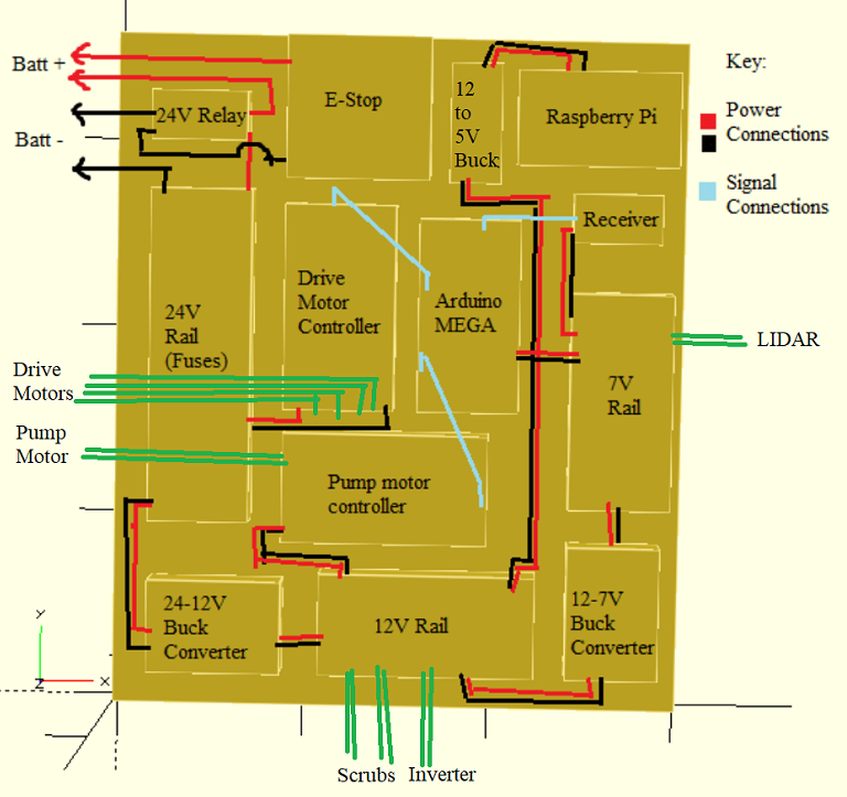
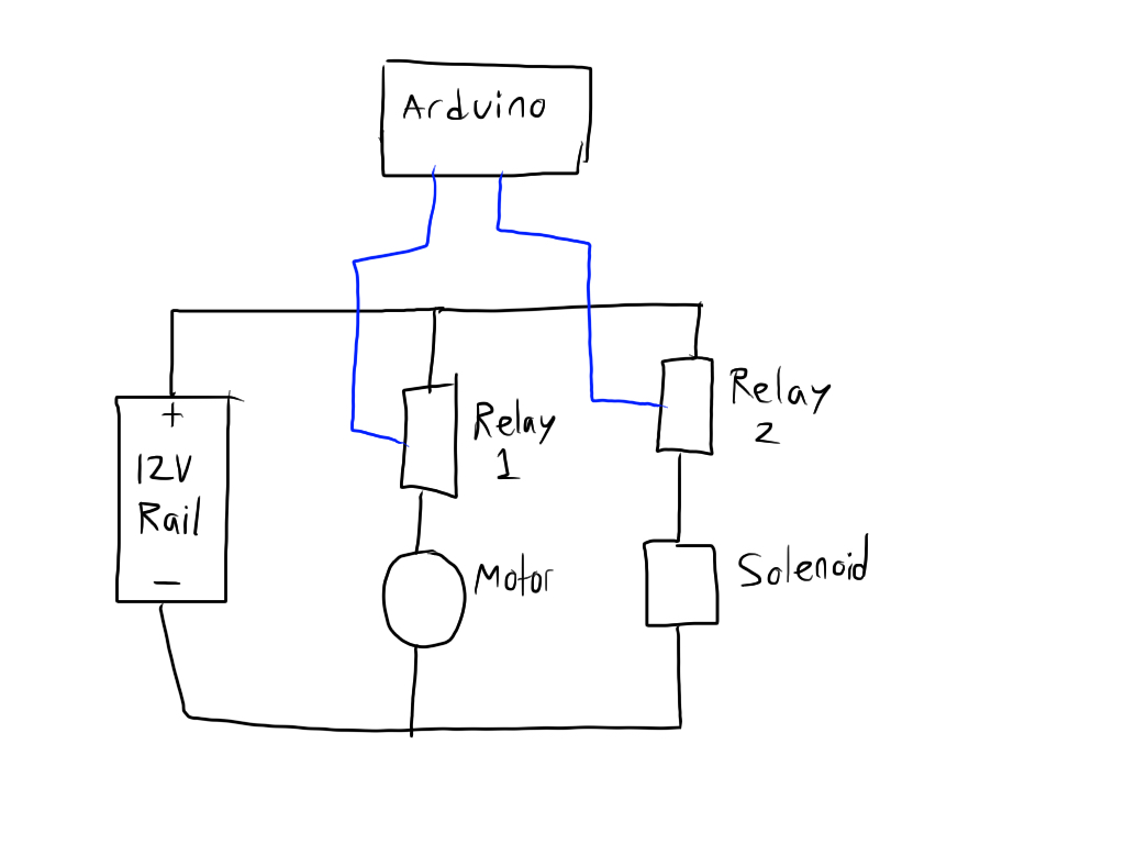
Nasi, Donn and I took apart the Growbot and started sketching out our plans for the electrical system. The plan currently is as follows.
24v battery
- Powers 24V inverter which runs 1200W vaccum
- Powers 4x 24V motors
24->12 buck converter
- Powers 2x scrub motors
- Powers LIDAR
- Powers Pump Motor
12->7 (or 24->7?) buck converter
- Powers Arduino
- Powers FlySky receiver
We calculated the current draw for 10 minutes for all components, and figured we will need a 24V, ~24Ah battery. The problem here is that these are highly expensive (rarely any less than 200$) and very heavy (upwards of 10 lbs).
In addition, the inverter is extremely heavy. All of this added weight increases the strain on the motors. The design as it stands is highly costly, all of these components totaling up to just under 800 dollars.
We as a team should discuss what our plans are for weight, power, and cost.
Quick Nick Solution ideas
- Downscaling in all ways: less water, smaller vaccuum (in terms of W and carrying capacity)
- Allowing for a smaller inverter, less heavy and less expensive
Fewer motors: 2 instead of 4Highly increases current draw on battery so not good
- Powering vaccuum off of AC cable instead of with the battery
- Removes need for inverter, the current draw of the vaccuum, and allows us to have a lighter robot and a smaller battery, but sacrifices “independence.”
- Jacob brought up the idea of powering the vaccuum seperately with a battery bank.
- He also brought up the idea that mounting stuff by drilling into the vaccuum will mess up the integrity of the vaccuum system and we should think of other ideas how to mount things.
I will update with the rest of the team’s ideas once we have formally met with the whole team again.
September 13, 2024
Nozzles have a variety of ratings:
3/8 in hose nozzles
- PSI to GPM calcs: https://www.omnicalculator.com/conversion/psi-to-gpm#psi-and-gpm
- Pump calcs: https://www.pumptec.com/blog/pump-spray-nozzle-selection-chart
- Looking at the above 2 calcs, if we use the Bayite pump (1.2 GPM and 80 psi) we will need ~8.5 nozzle. We want an evenspray pattern, but fan pattern works too. The angle should be a bit smaller, maybe 80 or even 40-45 degrees.
- Understanding nozzle sizes: https://www.dultmeier.com/understanding-the-numbers-on-a-sprayer-nozzle-a-comprehensive-guide
- Instead of getting the wrong nozzle, I can just get a variety (13.59)
- And to increase coverage, they can be mounted higher or lower!
- Since the bayite comes with 3/8 in (10mm) outlet & inlet, we need an adaptor that uses NPT (National pipe tapered) connections
Sep 16, 2024
Kill Switch considerations
- Alpinetech 24V killswitch
- Use a relay to implement (make sure also 24v)
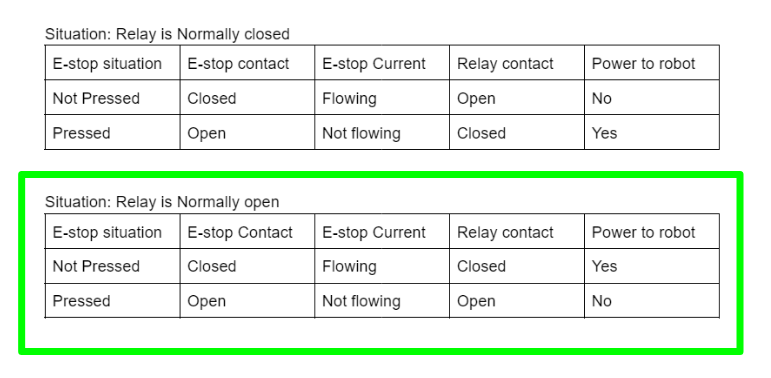
- Created a drawing replicating how we used a relay on last year’s robot:
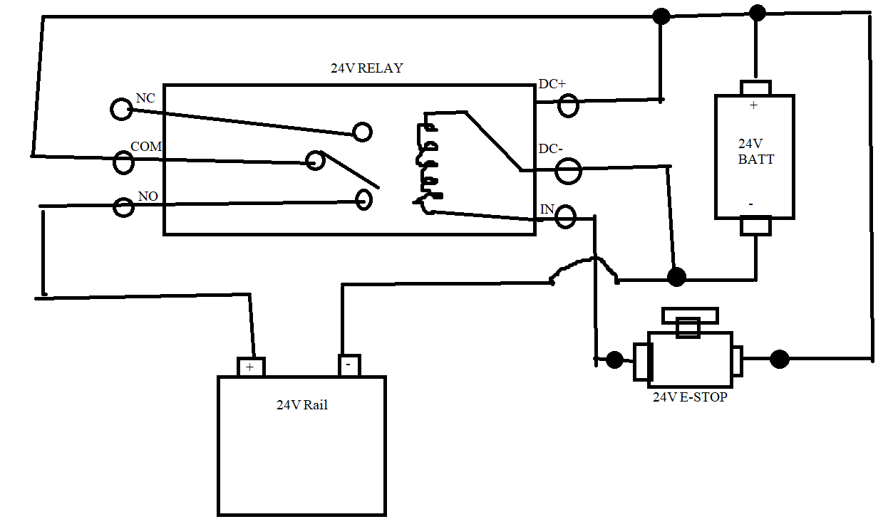
This is correct, but the drawing INSIDE the relay should have the contact touching the other side.
September 17, 2024
Concerns about Relay:
- 10Amp rating? – the motor controller is also only rated for 10A so that seems to be what we are using.
- Wire directly to E-Stop? – We don’t want current going through E-stop
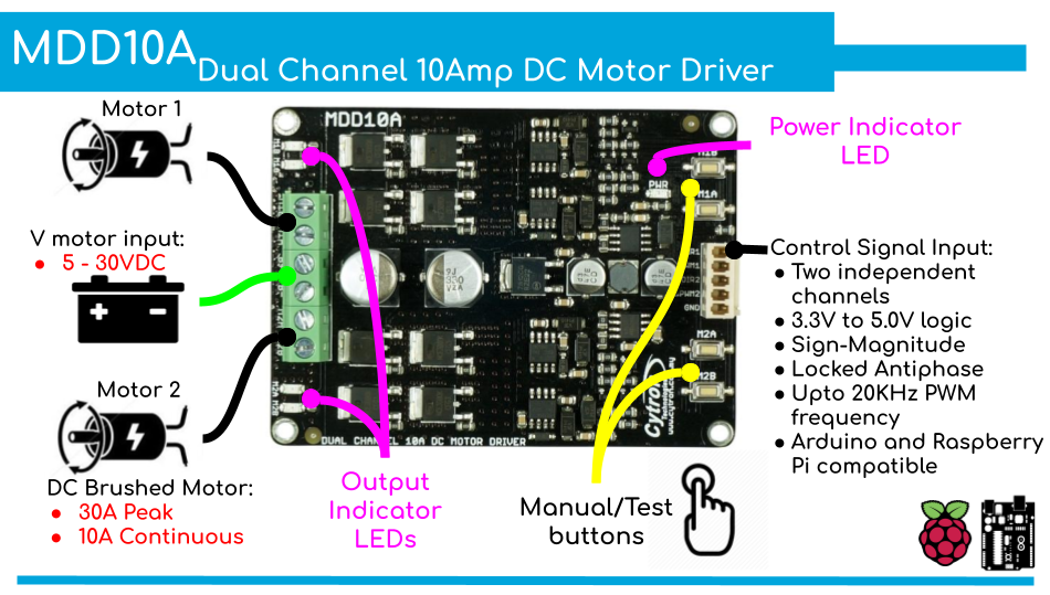
Idea of a motor controller to use: Cytron MDD10A
September 18, 2024
This morning I ordered most components, and EVERYTHING should be here by October 1, but before then we will start assembling things and cleaning up our drawings so hopefully everything works together well by critical design review.
We chose not to order anything related to the water distribution system yet because we want to have the vac moving first.
I think I will take a look at the wiring for the motor controller to make that more of a smooth process.
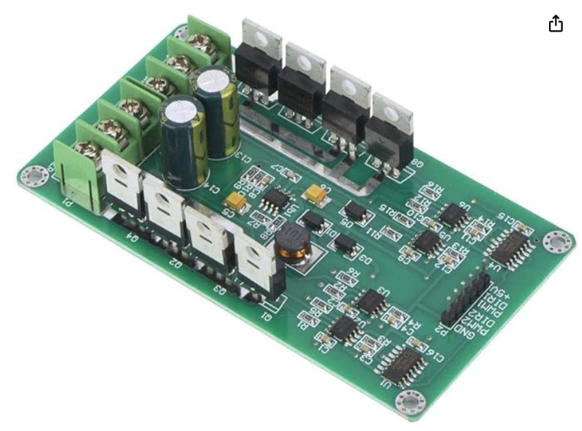
Ended up using this motor controller: Thincol Dual DC Motor Driver Module Board, H-Bridge DC 3~36V 10A Peak 30A Speed Control PWM Module, MOSFET IRF3205
September 19, 2024
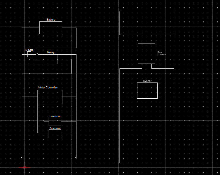
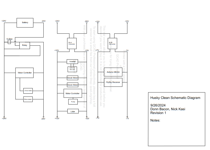
Donn showed a really clean way to represent electrical schematics:
 |  |
Normally open since the E-stop is normally closed.
Explanation:
Finished up GM presentation. Discussed creating mounts to allow components to be screwed onto electrical board
- Flysky receiver (“slide” into mount that is screwed to board)
- Small rails (have screws poking out)
- Buck converter (“clamp” onto lower board)
To do:
- Digitize Don’s diagram in QCad
- Make a wiring diagram in QCad
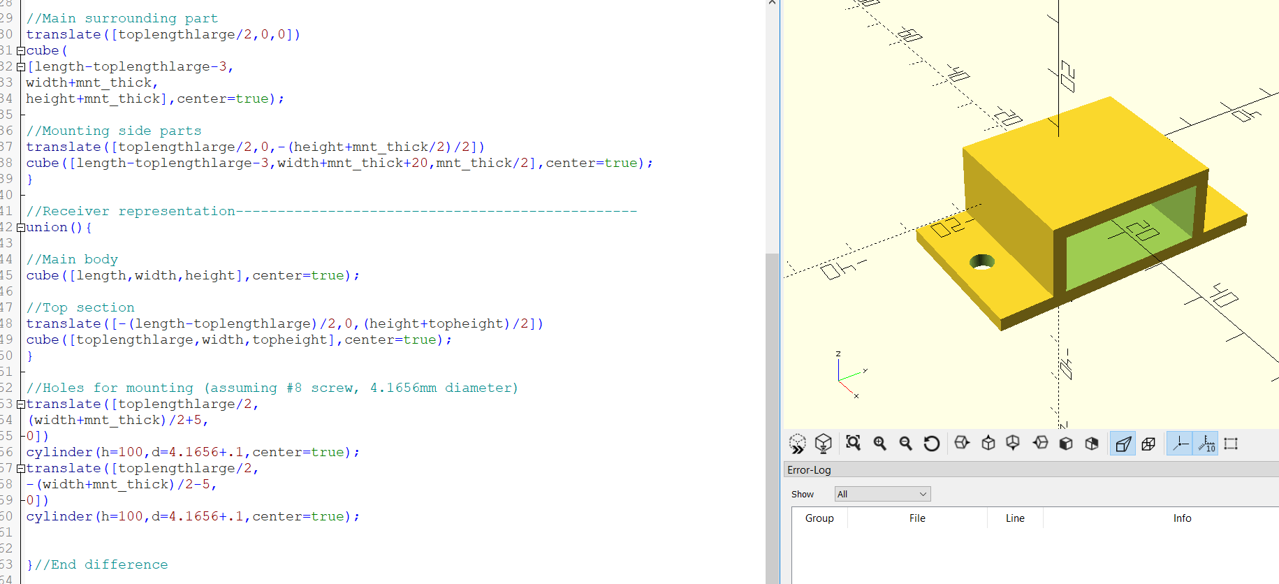
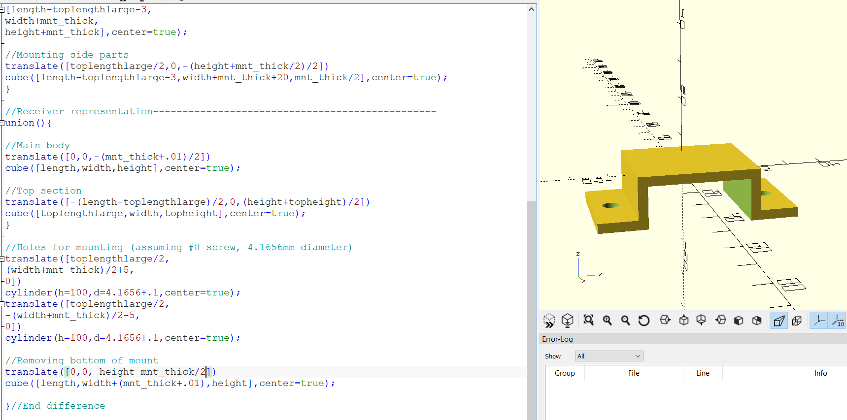
- Create mounts for FlySky receiver in OpenSCAD
- Create mounts for rails in OpenSCAD
September 23, 2024
OpenScad flysky mount — Openscad is kinda limited, maybe try OnShape?
WIP of QCad of electronics
September 24, 2024
Motor Controller: Dual DC
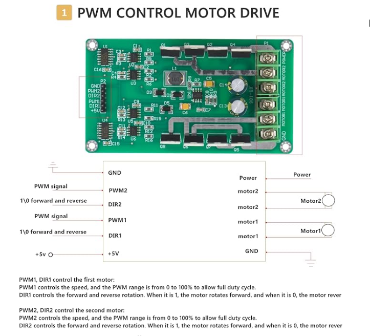
Reviews seem to have issues with the +5V. Hopefully not touching it won’t cause issues.
Code modification: PWM. Looked at arduino Growbot code to account for new motor controller
As a last resort, if we do have issues with the motor controller, we can run the motors at 12v off of the motor controller we have.
September 27, 2024
Tried printing flysky mount. Halfway through print, filament stopped extruding. Tried to replace filament, clear nozzle, and manually extrude, but no luck. Will work on this later.
September 26, 2024
Lab cleaning: cleaned sinks, organized nuts, bolts, screws.
OSHE Role: Worked on an “Intro” video for OSHE. Need to make a transparent version of the logo.
Changed the flysky mount a little so it holds on better and doesn’t go “around,” instead acting more like a bracket
Finished & printed schematic diagram
To do:
- Finish OSHE video
- Make mount for 12/7v rail
- Print FlySky Mount
September 27, 2024
In order to predict the size and layout of the electrical board, OpenSCAD was used to make to-scale versions of the electrical components and rotate them to all fit on the board.
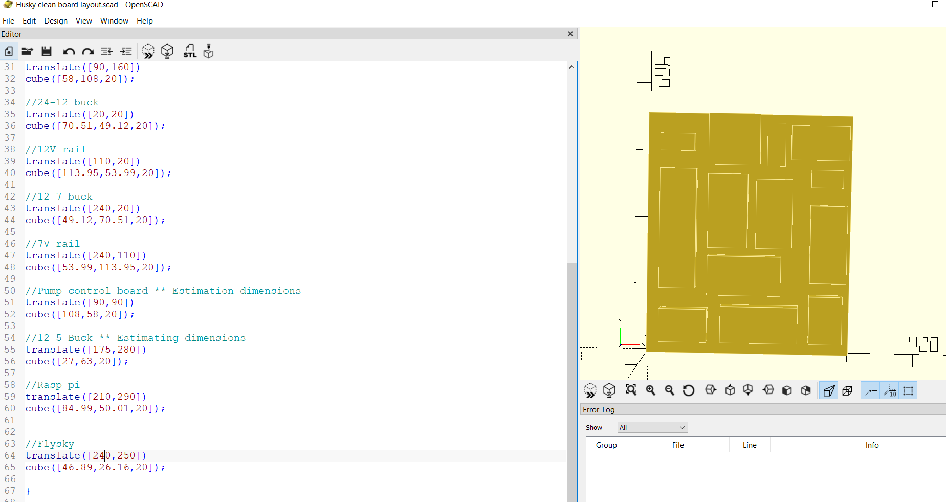
24V rail takes up a LOT of space despite only powering motor controller… But I don’t want the motors running off of something without a fuse.
Also, not sure about running the inverter without a fuse.
- We could get a 24V inverter too. Expensive though.
We could switch places of the 24 rail with the drive & pump motor controllers, and then re-position the buck converter. Might make wiring easier. We could also move the E-Stop off the board.
Week 6 (9/30 – 10/4 in Fall 2024)
This week, on Monday, we had our Critical Design review. We explained our different subsystems and our progress on them. Some questions people brought up involved control of the fluid dispensing system (intermittent, with relays), interactions between the bladder and the vaccuum (the suction occurs in the lid of the the vaccuum so it will likely not interfere), and our plans for the end of the semester (working RC drive and prototype of subsystems).
Some issues people brought up was safety in regards to water spilling. How are we going to empty the vaccuum without damaging any electronics? We discussed this afterwards and decided to have the vaccuum detachable from the frame, so it can be removed while closed and then brought to a different location to empty it out.
All of our components, except for the motor controller, were shipped, so we began assembling the frame and connecting the electrical system.
The frame will be larger than the robot and is constructed of multiple 80/20 bars. The vaccuum’s weight is supported by these bars as well, but we struggled to see how we would connect the vaccuum to the frame. Ultimately we ended up using heat-insert bolts and designing a 3d-printed mount to interface between the 80/20 bars and the bolt holes at the bottom of the vaccuum.
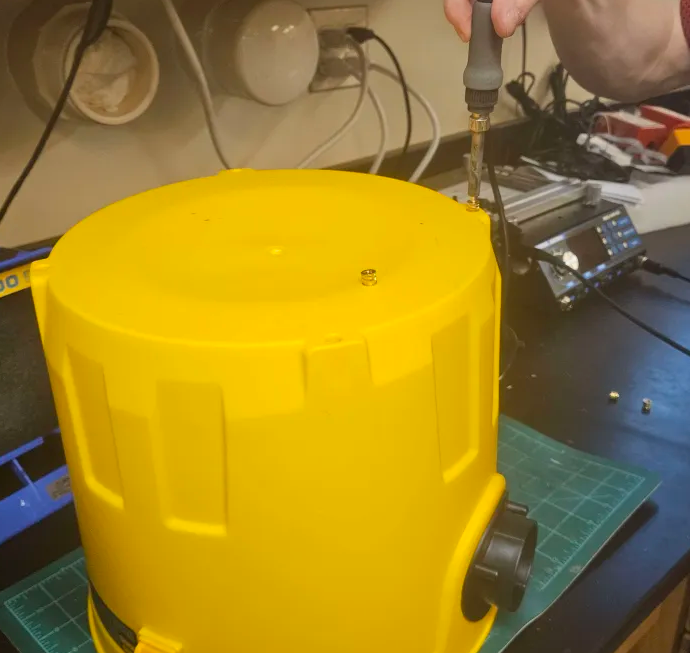
One issue we ran into very quickly was that the sizes advertised online were completely incorrect. The smallest side of the vaccuum (looking at it as a square) was allegedly 40x40cm, when in reality it was more like 15x15cm on all sides.
Since we are now mounting the electrical board on the frame, this is no longer an issue, but it did throw off a lot of our plans of mounting things to the vac itself.
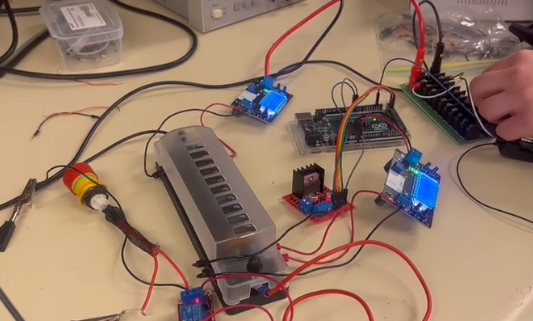
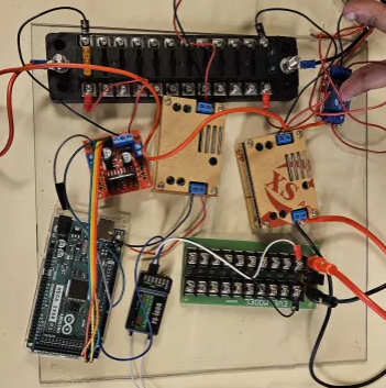
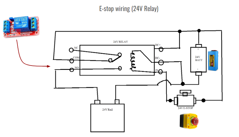
Next, we connected the 14V rail, the relay, and the E-stop.
We tested by running a small amount of voltage from a DC power source through the system, placing a fuse on the rail, and measuring over it with a multimeter. Ideally, when the switch is not pressed, there is power flowing, and when it is, the power cuts off.
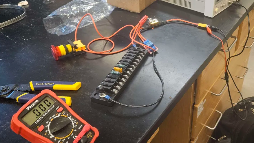
Already uploaded this image earlier, but this is the wiring setup we used.
One issue we ran into had the relay itself reacting to the E-stop being pressed (the red LED indicating what state it is in would turn on and off as expected), but we still would not see any voltage over the 24V rail. I looked around online for people with similar issues and one person suggested that “It sounds like the NO and COM connections aren’t making good contact. Perhaps they aren’t being pulled together strong enough due to not enough voltage or current being available for the electromagnetic coil in the relay.”
So, when we increased the test voltage from ~5V to 24V, the system started working as expected. Since this will be running off of a 24V battery, this will work on the robot itself.
Fluid system plans:
 |  |
Concerns:
Just thought of an issue. If I’m using our relays to control the pump, and the input signal is the arduino, that is likely not enough voltage to get the relay to trigger, right? I guess I’m not sure if the issue is the relay itself getting power, or the signal to activate the switch not being strong enough. Since the relay is actually being supplied power from the 12V rail, do you think it is fine? I can test it later I suppose.
We had a meeting with GM as well. Topics mentioned at GM meeting With direct drive:
- May be too fast
- Use chains/pulleys instead of gearbox
- See if you need to do a FEA (Finite Element analysis) on the drive system
- Raspberry PI
- Using Micro SD?
- For pump system
- See if it works without solenoid first
- Use relay system instead of motor controller
- Purchasing/budget concerns
- Contact Jason if costs are becoming an issue
Things to do:
- Create code for pump system
- Test the pump’s reaction to relays when it comes in!
- Plan ways to secure inverter and battery
- Screw down components to electrical board
- OSHE Video!
Week 7 (10/6 – 10/12 in Fall 2024)
This week, I printed some brackets for the 12v rail and the buck converter, and secured them down.
Then, I tried to test using the arduino to activate a relay signal.
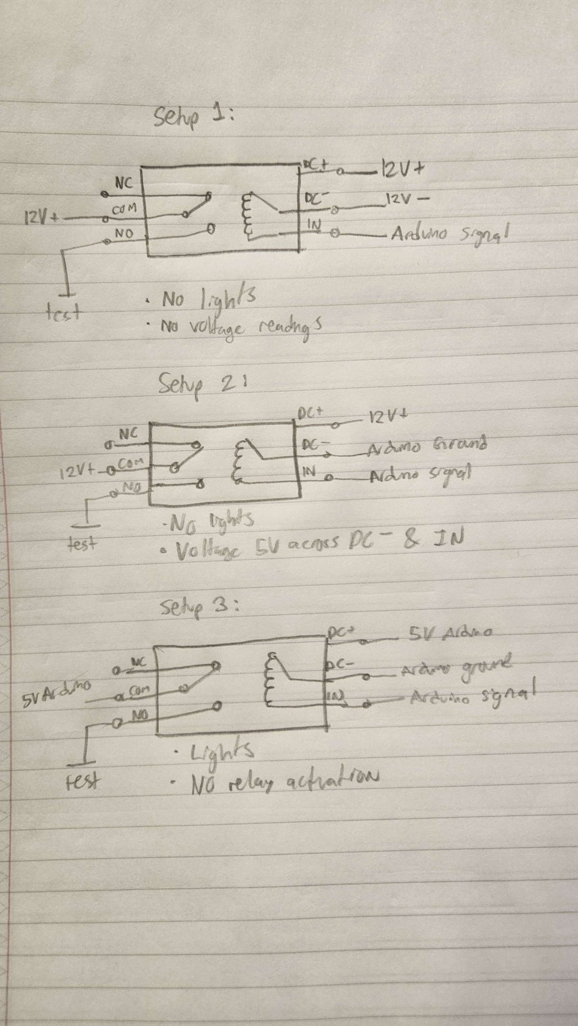
I did not manage to get it working with 12v input or a 5v input. I found some images online to help with troubleshooting relays.
https://forum.arduino.cc/t/relay-triggers-onwantted-on-startup/675930
- This person is even using the relay for a pump, however the issue stems in its reactions to starting up.
I think I may have to re-try it with this configuration
- Com: 12v+ NO: rail, and then 12v-
- In: arduino
- Input dc+: 5v
- Input dc-: 5v
And if that doesnt work, try the input dcs at 12v. My main concern when testing was sending too much voltage to the Arduino or somehow a large amount of current.
Week 8 (10/13 – 10/19 in Fall 2024)
We decided to return the inverter and look into expanding the frame, since it was far too large to fit onto our design. This works because we can power the vaccuum using a wall outlet for testing and in the future either replace the vacuum with a battery powered one OR find a smaller inverter.
We measured the inner diameter of the bladder tube to be 7.3mm. I will start designing a connection between it and the 3/8in hose.
We turned on the robot– the motors run very quickly but do not respond well to flysky inputs. We saw some issues where the robot would not respond, then realized the fuse for the motor controller was blown. We have to start current testing to see how much it is drawing and whether we need to add a higher fuse or if there is another issue causing this.
Some code debugging and investigation of the motor controller is in order. This was done by instead of responding to flysky inputs, we simply ran a code telling the motors to start and stop. One side was responding well, showing that the motor controller is functional (responding to PWM and DIR commands), but the other side was not working.
More figuring out pump stuff
1. In terms of the relay for the pump motor, this discussion on the arduino forums: https://forum.arduino.cc/t/connecting-relay-and-arduino-with-a-load/954350/9 suggests that the relay should be powered by a 12v source, and NOT the arduino! However, the ground for all devices should ideally be connected.
Mention for mosfets: “Better even than 12V relays would be to use (logic-level, n-channel) MOSFETs such as stp16nf06l or irlz44.”
Connect the ground from the battery with the ground from the arduino!! Right now arduino is being powered by the computer, so make sure there is at least one line grounding it.
2. https://www.instructables.com/Driving-a-Relay-With-an-Arduino
This website does a step-by-step instruction including code how to drive a relay with an arduino. However, it is using the 5v from the relay.
3. And another person using an arduino for a pump! https://forum.arduino.cc/t/trouble-with-12v-relay-attached-to-pump-arduino-mega2560/895675/10
In the comments, someone said:
You can use this relay module. The proper way to do it is to connect “DC +” and “DC -” to your respective 12 V supply terminals by a twin cable. Then remove the two jumpers and connect one or both “com” pins – depending on whether you want to use both relays – to either your Arduino ground if you wish to have the relay(s) active on HIGH, or to “5V” if you want them active on LOW.
Connect the respective “IN” terminal to your Arduino, keeping this wire together with the one connecting the “com” pin to the Arduino ground or “5V”.
4. https://forum.arduino.cc/t/arduino-mega-2560-and-8-channel-relay-module/473985/2
Overall, most people’s discussions are about how the arduino does not provide enough power to activate the relay, and using a 5V relay would damage the arduino. However, there is also a lot of discussion about protecting the arduino by isolating.
5. https://forum.arduino.cc/t/relay-connection/931031/2
It is HIGHLY recommended to make a “driver” circuit! However, this example is just using a MOSFET instead of the relay.
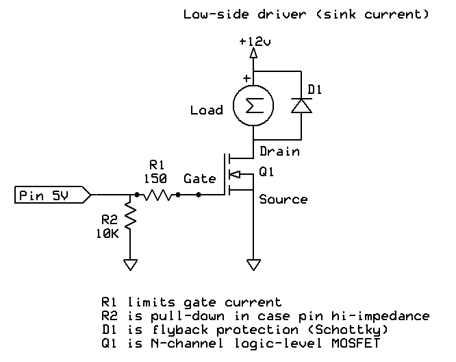
6. Another suggestion to isolate the arduino electronics from the pump: https://arduino.stackexchange.com/questions/28213/switch-pump-on-with-transistor-mosfet-or-relay
To do:
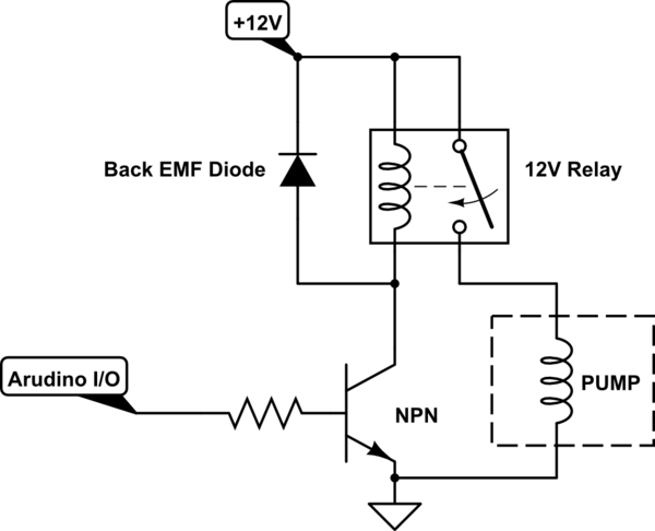
Thursday – Follow this https://www.instructables.com/Connecting-a-12V-Relay-to-Arduino
Will need:
- NPN transistor
- Diode
- 10k Resistor
Guys, am I cooked?
Friday, October 18, 2024
Meeting with GM
- Isolating the motors and testing how much current it pulls
- Test it with weight/delay
- Arduino relay boards are already isolated, so check schematics to see how that is done
- Old growbot current draw: Slower ramp-up speed (in code)
- Limit current with pwm
- Sand, or sawdust instead of kitty litter (kitty litter gets really hard to clean when it’s wet)
Issues connected Flysky Controller & Receiver
- The receiver and controller would pair, but after a few seconds, disconnect again
- The light on the receiver was very faint
- Troubleshooting for previous problem
- Tried pairing receiver and controller in different ways (turning different device on first, removing pairing key, etc)
- Tried using a different receiver
- Tried using a different controller
- Tried using an arduino UNO instead of MEGA (to see if arduino was having any issues)
- Still had same issue for all previous cases
- The arduino was supplying 5V to both the motor controller and the receiver
- Solved by supplying 5V to controller & receiver from a separate power source, not the controller
Testing that motors work
- Directly power them at 24V
- Both would run when power was connected
- Both ran at .5A of current. Inrush current was not detected
- Both motors seem to work fine in isolation
Testing motor controller
- Motor 1 was not drawing any voltage or moving
- Motor 2 was drawing about -1.9V and moving with inputs to code.
- Could be due to slow speed from code
Testing PWM communication from arduino
- Incomplete results. Was seeing weird waveforms on oscilloscope.
- Tried again. Saw square waves coming from PWM for Motor 1 and Motor 2.
- Motor 1 square wave: 970Hz, 80us
- Motor 2 square wave: 488Hz, 1.60ms
- Idea 1 (we figured out this was not the issue): Maybe the high frequency and small square wave is causing the motor controller to have issues reading PWM?
- This was disproven because we connected the high frequency PWM input into motor 2, and motor 2 ran fine. Then we connected the low frequency PWM input to motor 1, and it still did not move.
- So, we concluded that our motor controller was not functional for controlling Motor 1.
Issues updating code on arduino
- This is a problem with Nick’s computer, not the arduino. However, it makes looking at serial print communications complicated.
- Driver issue? Check with Lindsey.
The Pump Relay endeavor continues…
Based off this link, used a PN2222A transistor and a 1N4004 diode.
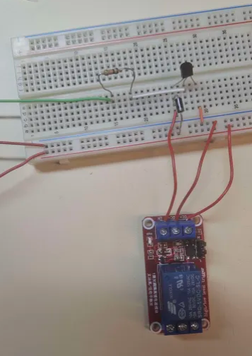
I applied 12V + and – to the red leads, and 5V+ to the green lead (would be coming from arduino).
The power light turned on, but NO switching happened.
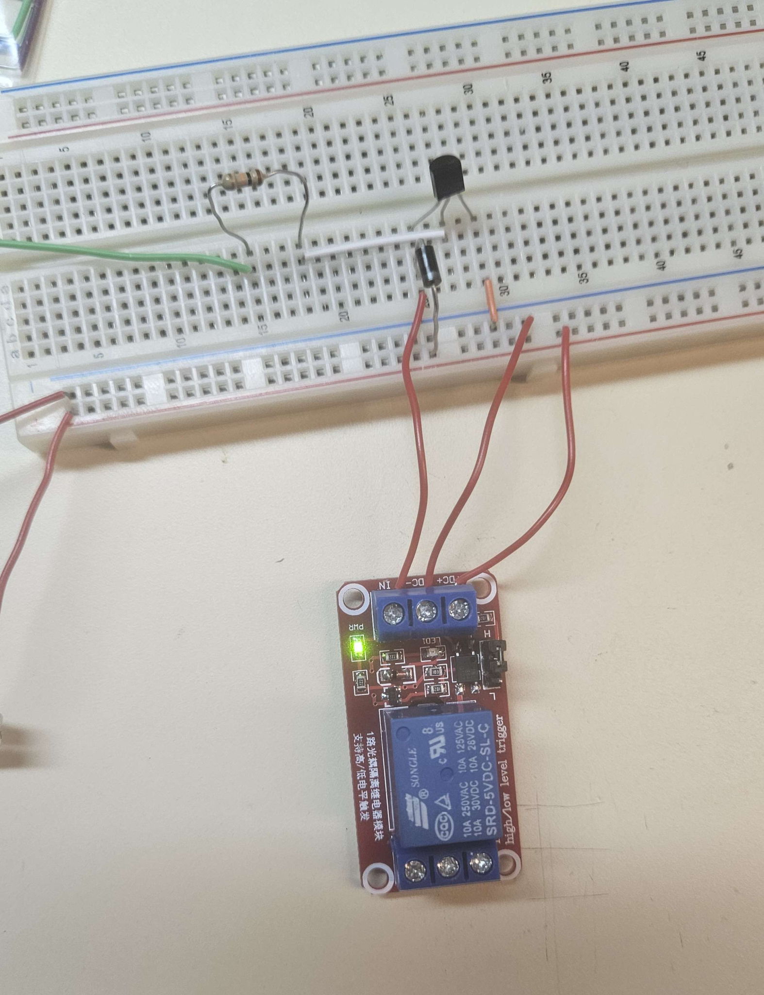
Then, I switched the relay from trigger on high to trigger on low.
 |  |
Then, the power light was on, AND the relay switched.
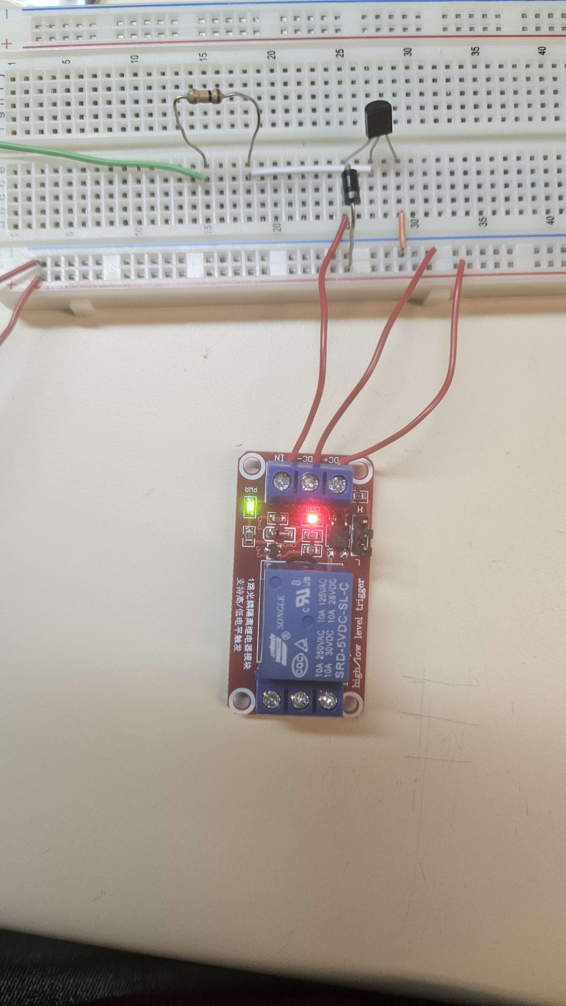
This shows that the way I was connecting the IN signal is not correct. I had it as 5V grounded at the same place everything else is grounded. Maybe the 10k resistor stepping down was too much.
- Removing the 10k resistor led to pretty high current (specifically 1.57A at 2.12V)
To do:
- Make WIRING diagram (not schematic)
October 21, 2024
Is it possible that 12V is the switching voltage? Test just straight up if 5V in switches.
- If not…
- Get a 5V relay
- Or, amplify input signal
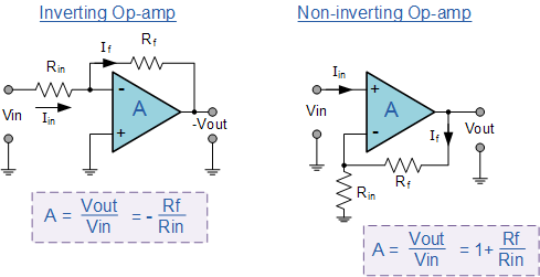
5V > 12V needs amplification of 2.4.
- Check if slightly above or below 12V works too.
- Then, simply have Rf/rin = 1.4.
October 22, 2024
Finally some progress in testing the pump controls. I realized that the relay board I was using is ALREADY opto-isolated, so I should be able to directly use it on the Arduino MEGA. Then, I realized as a 12V coil voltage, that only applies to the DC power needed, not the actual switching signal. So, I applied 12V on the DC+ and DC- ports, and then grounded a 5V dc supply at DC- and applied the positive lead to IN. This caused it to switch. I decreased the voltage and found that switching occurs somewhere between 1V and 1.4V. The voltage on an arduino MEGA pin is 5V when high, 0V when low. So, this should be sufficient to switch on the relay.
October 27, 2024
We have been repeatedly having issues with the Arduino MEGA. Most notably, it does not appear on the arduino IDE, and thus it is impossible to update code on it. I first noticed this on October 18, but at the time I thought it was an issue with my laptop and I updated drivers and re-installed the arduino IDE. Frustratingly, I could not find the MEGA in my device manager, where a lot of the solutions were recommended for reinstalling drivers. However, recently Lindsey (who had been updating the majority of the code) reported the same issue.
When I plug my laptop into an arduino UNO, it does indeed show up in the arduino IDE.
I tried to see if anyone had similar problems.
https://forum.arduino.cc/t/mega-wont-show-up-in-device-manager/636486/3
- I tried uninstalling and reinstalling the Arduino AVR Boards in Tools>Board>Board Manager. This had no effect
- I couldn’t manually update drivers because the MEGA does not show up in the device manager https://docs.arduino.cc/tutorials/generic/DriverInstallation/
- Another option was to use an arduino UNO to program the MEGA, if the USB connection seems to have issues. I wanted to try this, but first I checked if I could upload code to the UNO. I ran into this issue: https://forum.arduino.cc/t/avrdude-cant-open-config-file-no-such-file-or-directory/435699/6
- So, I uninstalled the arduino ide and re-installed it, removed the avr boards and re-installed them.
- Still had the same error… Tried this https://forum.arduino.cc/t/solved-compilation-error-arduino-avrdude-6-3-0-arduino17-is-not-installed/701550
- FINALLY I got the UNO code working
- Go into file explorer, (View at the top, options, change folder and search options, view tab, show hidden files, OK)
- This PC>Windows SSD>Users>Your name>AppData (will be a hidden folder)>Local>Arduino 15
- Then, I deleted “packages” (if this doesn’t work, restart your computer)
- Then, I went into the Arduino IDE Tools>Board>Board Manager and uninstalled & reinstalled the board
- Now time to try programming it
Overall bootloader info (main): https://docs.arduino.cc/built-in-examples/arduino-isp/ArduinoISP/
Mega using uno specific: https://forum.arduino.cc/t/solved-program-mega-using-uno/392397
Issue someone had: https://forum.arduino.cc/t/programming-arduino-atmega-2560-with-a-arduino-uno/1051324/4
Finally, I also tested the pump. The hoses seem to fit decently, but I could not get the pump to turn on by applying 12V to it, either with or without the hoses. I even primed them with water despite it being a self-priming pump, but no luck. I’m going to look up potential issues for this.
October 29, 2024
The LIDAR should be wired off the 24V with a 3A slow-blowing fuse. Jacob has more info:
Since the MEGA is broken, we connected the Arduino UNO to the flysky to test some code.
Connecting the Flysky Receiver to the UNO requires ALL PWM ports. So, it is not really possible to use PWM motor controllers in this scenario. There are some examples of using other motor controllers: https://www.youtube.com/watch?v=q-Clw0m3E18
Wiring between Arduino UNO and Receiver: https://dronebotworkshop.com/radio-control-arduino-car/
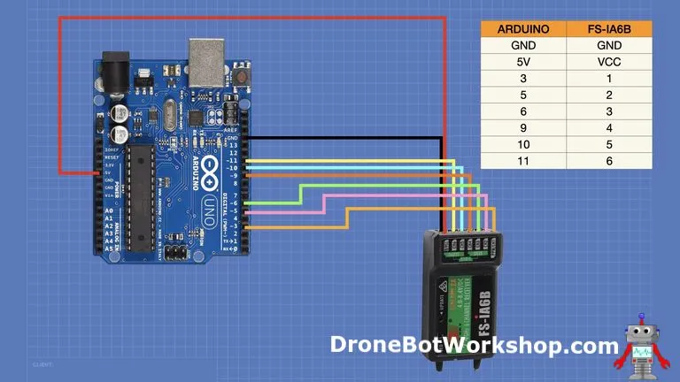
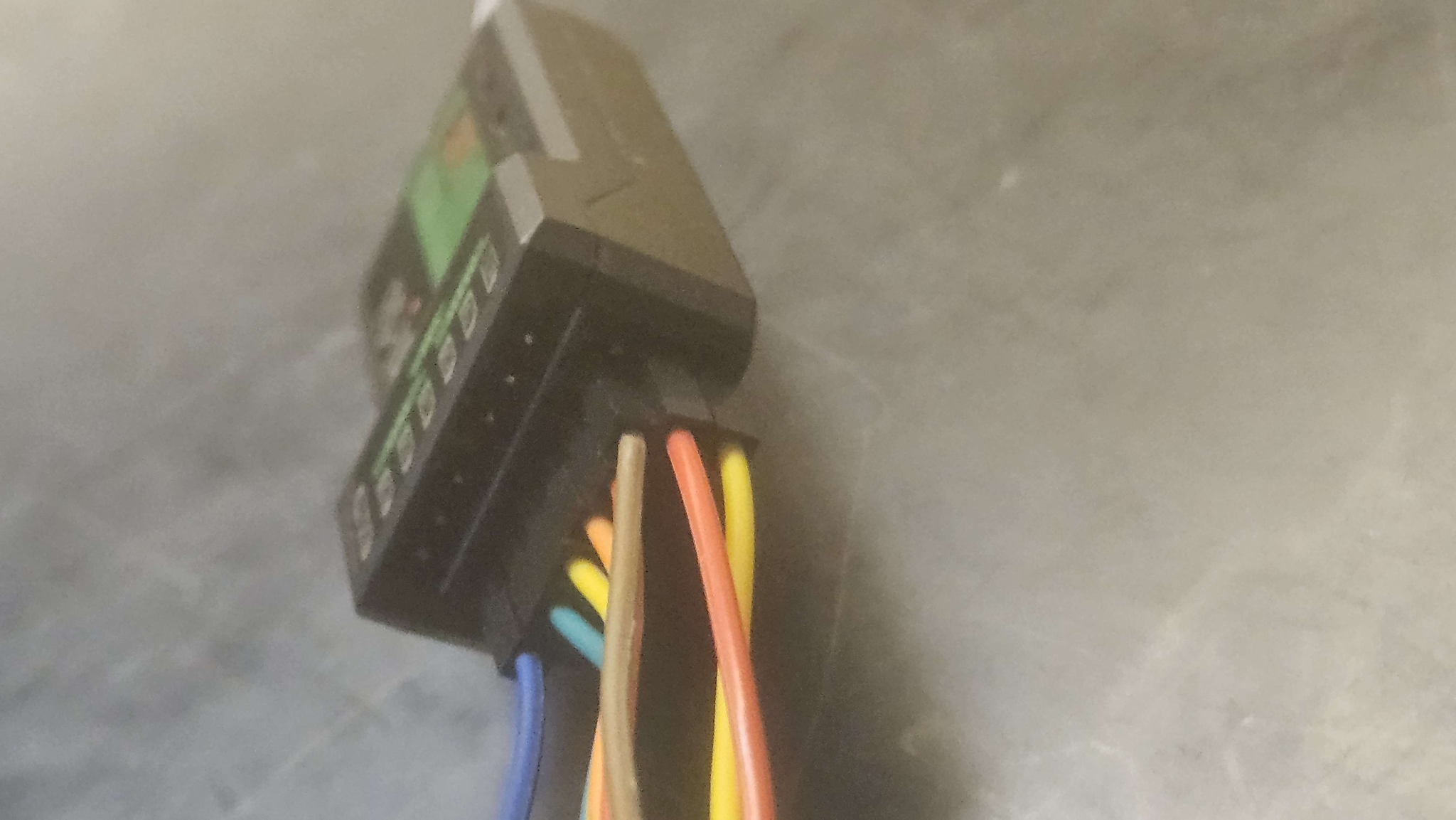
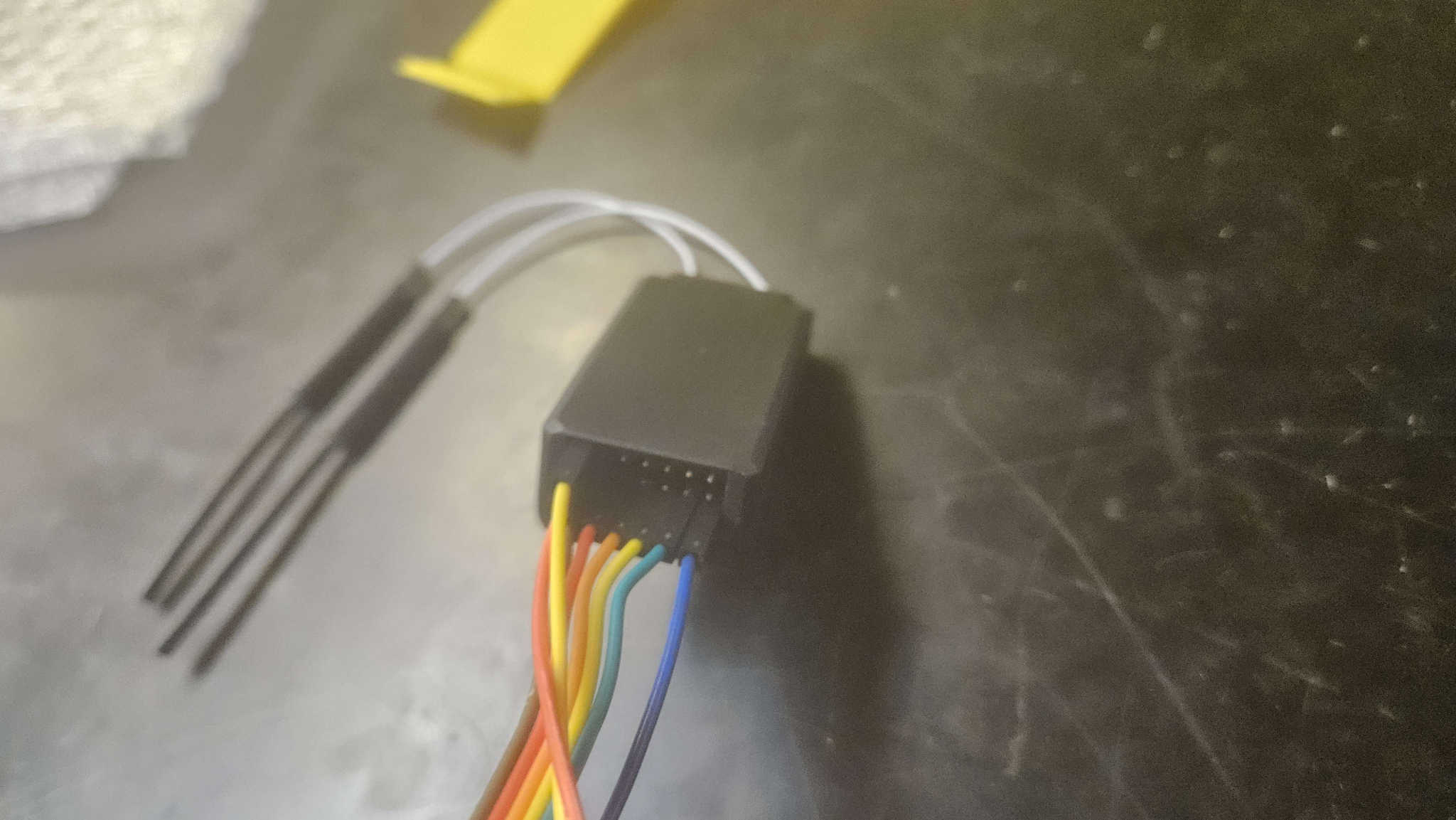
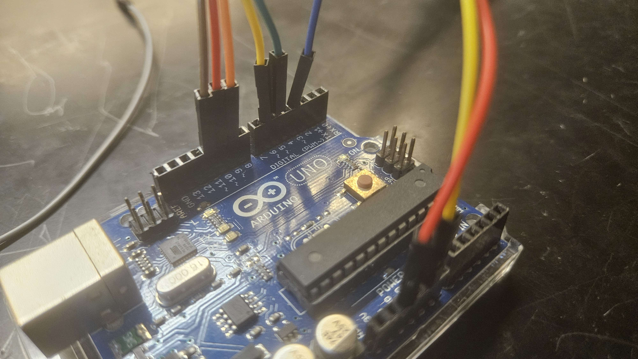
Code based on Arduino UNO for DroneBotWorkshop: https://dronebotworkshop.com/radio-control-arduino-car/
Using digitalwrite to set Pin 13 to HIGH if Ch 5 is positive (first switch): https://docs.arduino.cc/language-reference/en/functions/digital-io/digitalwrite/
/*
  Arduino FS-I6X Demo
  fsi6x-arduino-uno.ino
  Read output ports from FS-IA6B receiver module
  Display values on Serial Monitor

  Channel functions by Ricardo Paiva - https://gist.github.com/werneckpaiva/

  DroneBot Workshop 2021
  https://dronebotworkshop.com
*/

// Define Input Connections
#define CH1 3
#define CH2 5
#define CH3 6
#define CH4 9
#define CH5 10
#define CH6 11

#define DirF 13


// Integers to represent values from sticks and pots
int ch1Value;
int ch2Value;
int ch3Value;
int ch4Value;
int ch5Value;

// Boolean to represent switch value
bool ch6Value;

int FluidDir = 0;

// Read the number of a specified channel and convert to the range provided.
// If the channel is off, return the default value
int readChannel(int channelInput, int minLimit, int maxLimit, int defaultValue){
  int ch = pulseIn(channelInput, HIGH, 30000);
  if (ch < 100) return defaultValue;
  return map(ch, 1000, 2000, minLimit, maxLimit);
}

// Read the switch channel and return a boolean value
bool readSwitch(byte channelInput, bool defaultValue){
  int intDefaultValue = (defaultValue)? 100: 0;
  int ch = readChannel(channelInput, 0, 100, intDefaultValue);
  return (ch > 50);
}

void setup(){
  // Set up serial monitor
  Serial.begin(115200);

  // Set all pins as inputs
  pinMode(CH1, INPUT);
  pinMode(CH2, INPUT);
  pinMode(CH3, INPUT);
  pinMode(CH4, INPUT);
  pinMode(CH5, INPUT);
  pinMode(CH6, INPUT);
  pinMode(DirF,OUTPUT);

}


void loop() {

  // Get values for each channel
  ch1Value = readChannel(CH1, -100, 100, 0);
  ch2Value = readChannel(CH2, -100, 100, 0);
  ch3Value = readChannel(CH3, -100, 100, -100);
  ch4Value = readChannel(CH4, -100, 100, 0);
  ch5Value = readChannel(CH5, -100, 100, 0);
  ch6Value = readSwitch(CH6, false);

  // Print to Serial Monitor
  Serial.print("Ch1: ");
  Serial.print(ch1Value);
  Serial.print(" | Ch2: ");
  Serial.print(ch2Value);
  Serial.print(" | Ch3: ");
  Serial.print(ch3Value);
  Serial.print(" | Ch4: ");
  Serial.print(ch4Value);
  Serial.print(" | Ch5: ");
  Serial.print(ch5Value);
  Serial.print(" | Ch6: ");
  Serial.println(ch6Value);

 // looking for any dial movement for fluid System beyond a point
  if (ch5Value > 0){
    digitalWrite(DirF, HIGH); // relay set to high
  }else{
    digitalWrite(DirF, LOW); // relay set to low
  }


  delay(500);
}
I’d like to thank Lindsey for hard carrying me with this code.
You can tell signal is setting the pin states correctly by LED 13, which turns on when pin 13 is high: https://forum.arduino.cc/t/blinking-l-light/87477
When wired to 12v, with IN being connected to pin 13, DC- being connected to 12V- AND the arduino ground, and DC+ being connected to 12+, the LED on the relay would turn on, but it would not switch.
Is it possible that because it is a 24V relay, it needs 24V to operate?
I attempted to recreate the system with the Arduino off of a power supply instead of the battery for 12V, but suddenly the relay would not even turn on LED to indicate switching.
Then, when plugging it into the 24V line, it would not turn on the LED either.
Finally, the pump was connected to the 12V line and it made some suction noises, but I did not run it for very long to avoid damaging it (since there was no water flowing).
October 30, 2021
Today, I was bone tired… But I did get training with the Miter saw at the Alley makerspace, and managed to get the new electrical boards set up. If you were in the lab and saw me struggling to fit a 14AWG wire into the DROK buck converters for 45 minutes, no you didn’t.
- New arduino MEGA found, wired up
- Cut 3 electrical boards with the Miter saw at the Alley (Thank you to the extremely patient people working there that helped me out)
- One was too hard to use (couldn’t screw in screws manually), used other 2
- Set up components so connections can be done across boards
- Mounted most components, need more mounting screws/prints
- Plugged in and confirmed all components working
- Waiting on last motor controller
- Still need final pump test & wire to relay
October 31, 2021
Updated GM Presentation:
- Pump fluid test 1: FAILED
- Connected pump to 12V DC power supply, with intake connected to filled bladder and transferring to a hose.
- Hoses were sized properly, able to connect to the barbs of the pump
- No response from the pump
- Unable to tell if any leaking would occur
- Control testing: SUCCESS
- Several relays available: 5v, 12v, 24v. Originally assumed to be max voltage that could be connected on load end of relay. However, this is COIL voltage. This means that 5v, 12v, 24v must be supplied to relay for normal operation. So, 24V relay will not function properly with 12v
- Switching occurs between 1V and 1.4V, and high on Arduino is 5V, so this is PLENTY
- Arduino current limit per pin: 40mA
- Isolation concerns
- Relay is an inductive component, contains coils
- Back EMF may be an issue if using Arduino signal for switching
- Suggestion from last time: Checked the board wiring–the modules we purchased are already opto-isolated, containing transistors & diodes, so we can directly wire them without any concern. Saves some effort & money!
Cut new electrical boards (x2) with Miter saw, table saw, Jigsaw
Wired new motor controller
Receiver works best wired directly to arduino
Used oscilloscope to adjust outputs from arduino according to receiver input
Power (Watts) = Voltage * Current
Shaft torque = Power(watts) / (2*Pi*speed/60)
Mechanical power (horsepower) = torque* operating speed
https://electronics.stackexchange.com/questions/84552/limiting-current-for-a-dc-motor
Weeks 11-12
Cut new electrical boards
Wired up motor controllers, but they were not working. Identified a soldering disconnect, and attempted to re-solder it. Found motor controllers kept tripping fuse. Removed motor controllers and attempted control with L298N, but since they are 12V 2A motor controllers simply could not supply enough power to spin motors. Ordered new motor controllers: HiLetgo BTS7960
Replaced 5a 24-12 buck with two 10a bucks.
Wired relay for Scrub brushes and pump
Created Pump mount and E-stop mount
Created OSF repository
Week 1 (Jan 6, 2025 – Jan 12, 2025)
We had a meeting to talk about any concerns, ideas, or goals our team had. Some things that were brought up…
- Replacing the shop vac
- This would allow the vaccuum to operate independently of a wall plug. It will cause minor frame redesigns to mount it to the frame, and any difference in dimnesion will cause potential re-arrangement of components (for example, it may hang over the side but leave space for more room in the front)
- Replacing the bladder with a solid jug
- This would make mounting a lot simpler, be very cheap, but potentially cause issues with space. However, it is decently reliable.
- Placement/wiring of the LIDAR
- The LIDAR has 3d printable brackets available, so mounting shouldn’t be an issue. There was a lot of difficulty finding documentation for wiring, so Dr. Pinar was contacted as someone who had experience in the past using this LIDAR.
We tested the pump. It takes a bit to engage, but it is able to draw water out of the bladder and push it through the hose. The pressure is not extremely high, but it does not leak and the bladder handles the suction fairly well.
Week 2 (Jan 13 – Jan 19, 2025)
We met with Dr. Pinar to get assistance with wiring the LIDAR.
Our LIDAR is a multiScan165, which is in the multiScan100 family. It came with 2 cables: a 12 pin power cable, and a 4 pin ethernet cable. We are using a raspberry Pi and an arduino to interface between the LIDAR and the Husky Clean.
Link to LIDAR: https://www.sick.com/us/en/catalog/products/lidar-and-radar-sensors/lidar-sensors/multiscan100/muls1aa-114322-multiscan165/p/p680210
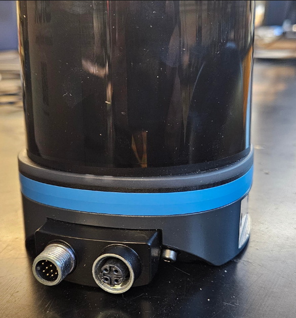 | 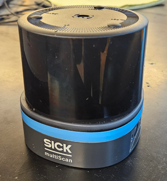 |
| Port side | Blank side |
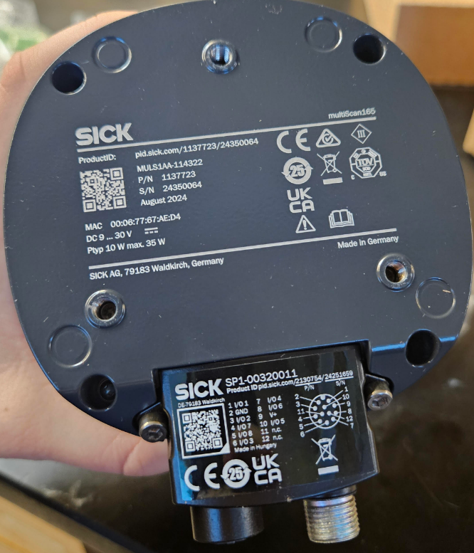
Cables:
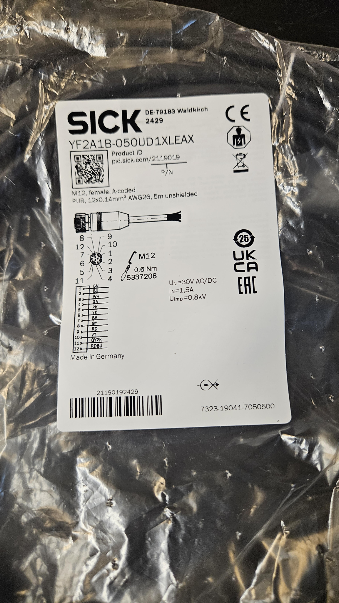
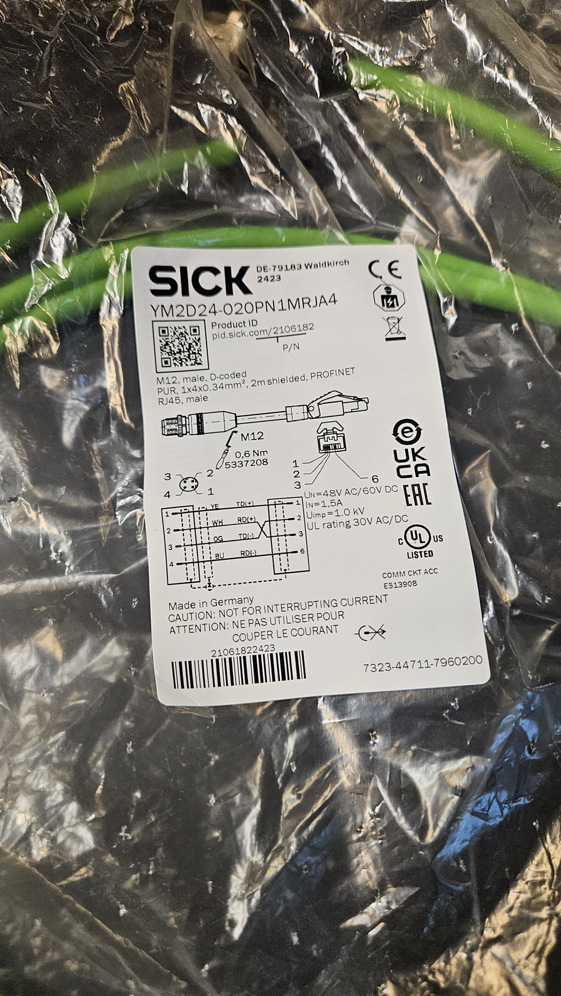
The black power cable ends in a pigtail. Most of these cables are for sending data, but this can also be done by the ethernet cable. So, only 2 cables are used for the power cable to provide power. This is Pin 2 (blue) for negative and Pin 9 (red) for positive.
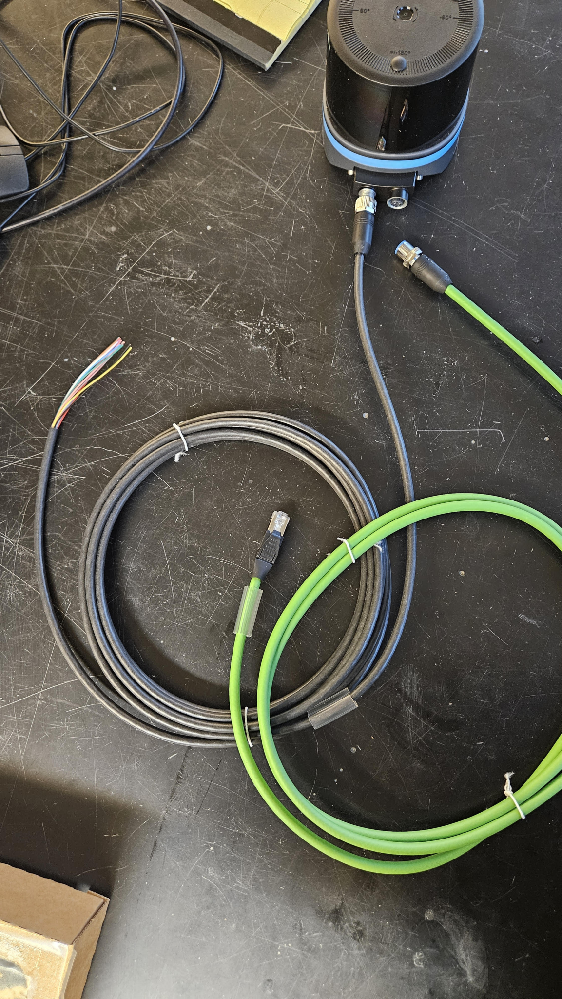
Ultimately, we hooked up the blue and red wire appropriately and applied 24V from a 0.5A power supply. The LIDAR lit up red, flickering slightly. It likely needs a power source with more current.
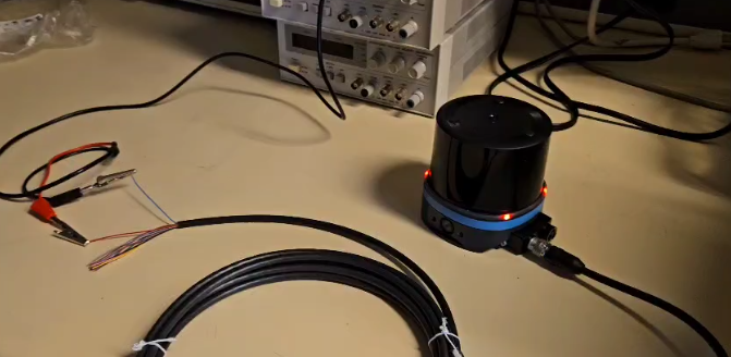
Then, we removed all electrical boards, E-Stop, pump, and vacuum from the frame to allow Seth space to redesign the frame for the new vacuum.
Things to purchase:
- Material for water cover
- Relay for vacuum controls
- Anything needed to make own Dupont wires
Looking into whether to get Acrylic or ABS for waterproof cover:
ABS
- Matte black ABS – 18 – 12”x16” (x6)
- Use evostik impact to join ABS together
Acrylic
- Clear acrylic – 22 – 36”x24”
- Acrylic hinge?
Create cover using cardboard, or measure out all lengths when boards are back on and estimate what mounts will be needed
- Hinge to replace battery?
- Overall have top & side facing robot be solid, but back can have gaps?
- Does vac kick up water?
Find the wires and start implementing them if possible.
Week 3 (Jan 20, 2025 – Jan 26, 2025)
We connected the LIDAR wires to the 24V rail and plugged it in. The LIDAR lights turned from red to green. In addition, we have an ethernet-usb connector to use for data transfer.
I am working on connections between the motor controllers on the bottom board and the arduino/5v rail on the top board. These will be easily disconnectable but more organized.
To do:
- Motor controller mount print
- LIDAR mount print
- Water tube print test
- Bladder claw print
- Dimensions for acrylic
- Wait for wires & finish board-bridging wires
Sketch:
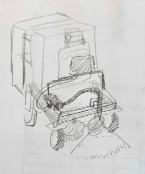
Week 4 (Jan 27, 2025 – Feb 2, 2025)
After the new vacuum was mounted, we re-measured how much space was available to plan mounting the pump, reservoir, and LIDAR.
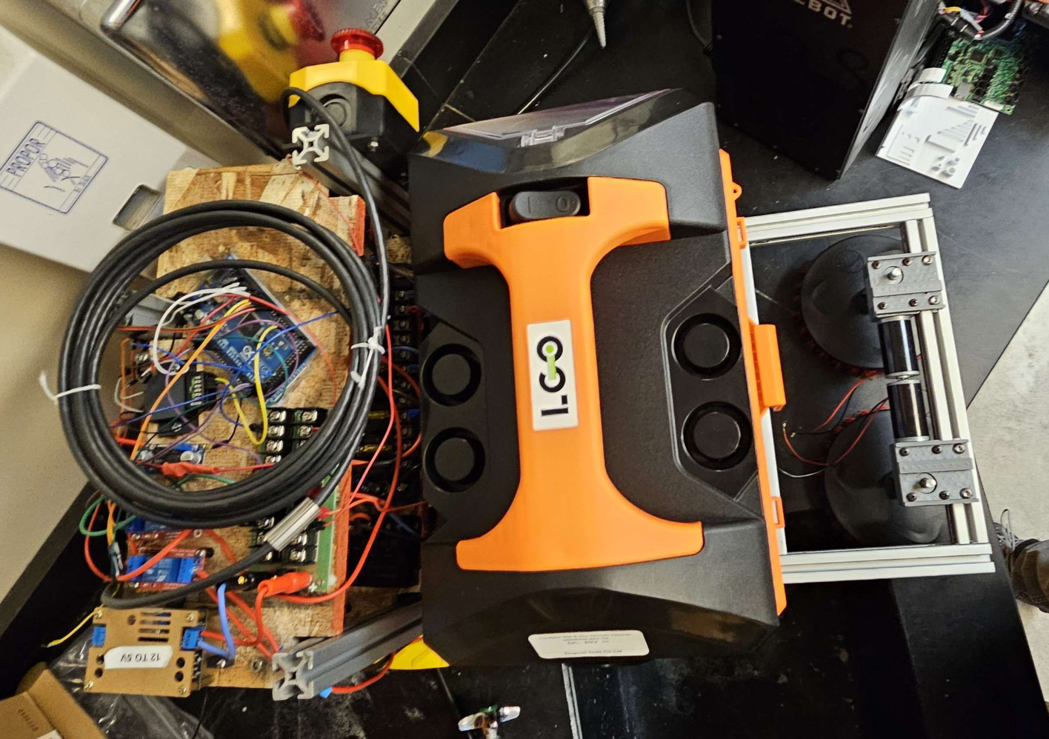
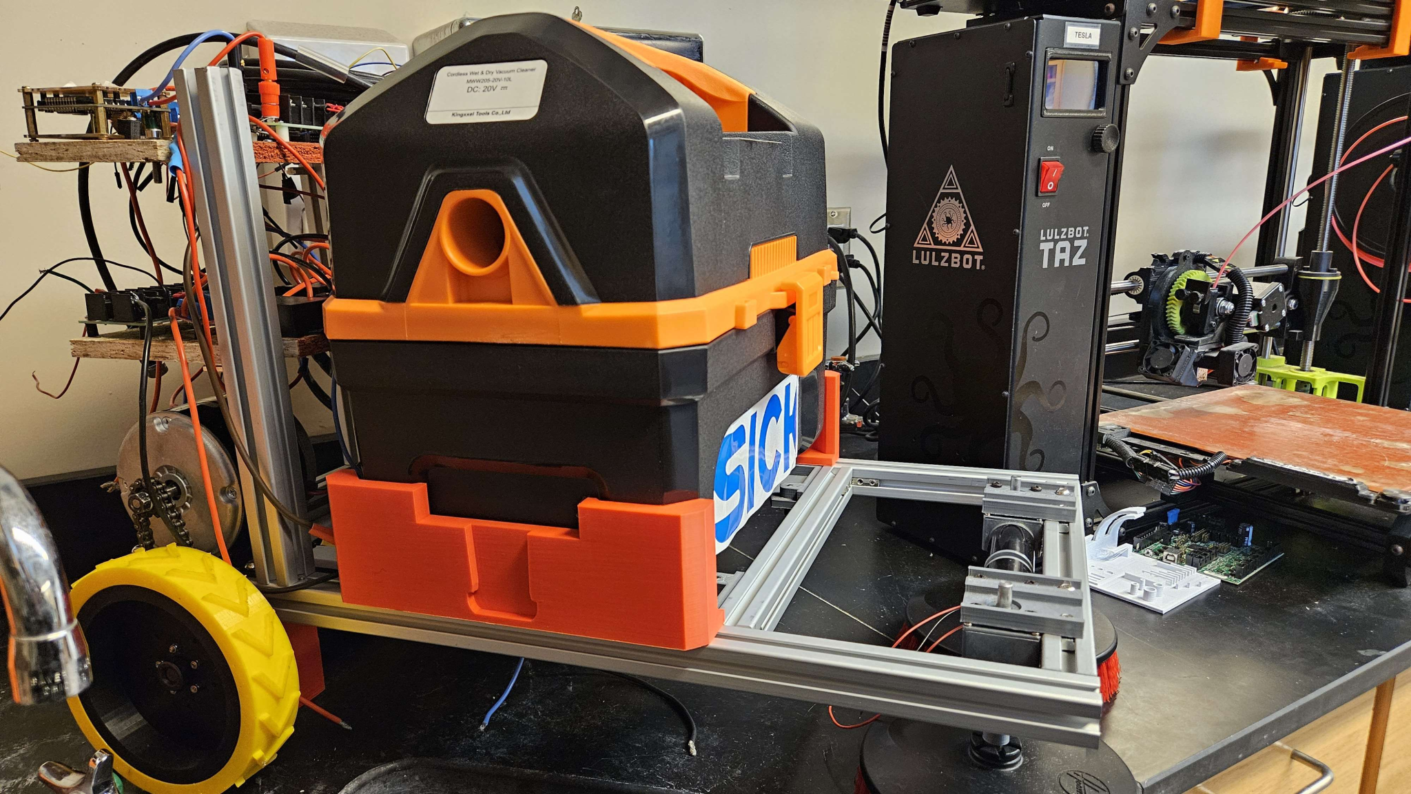
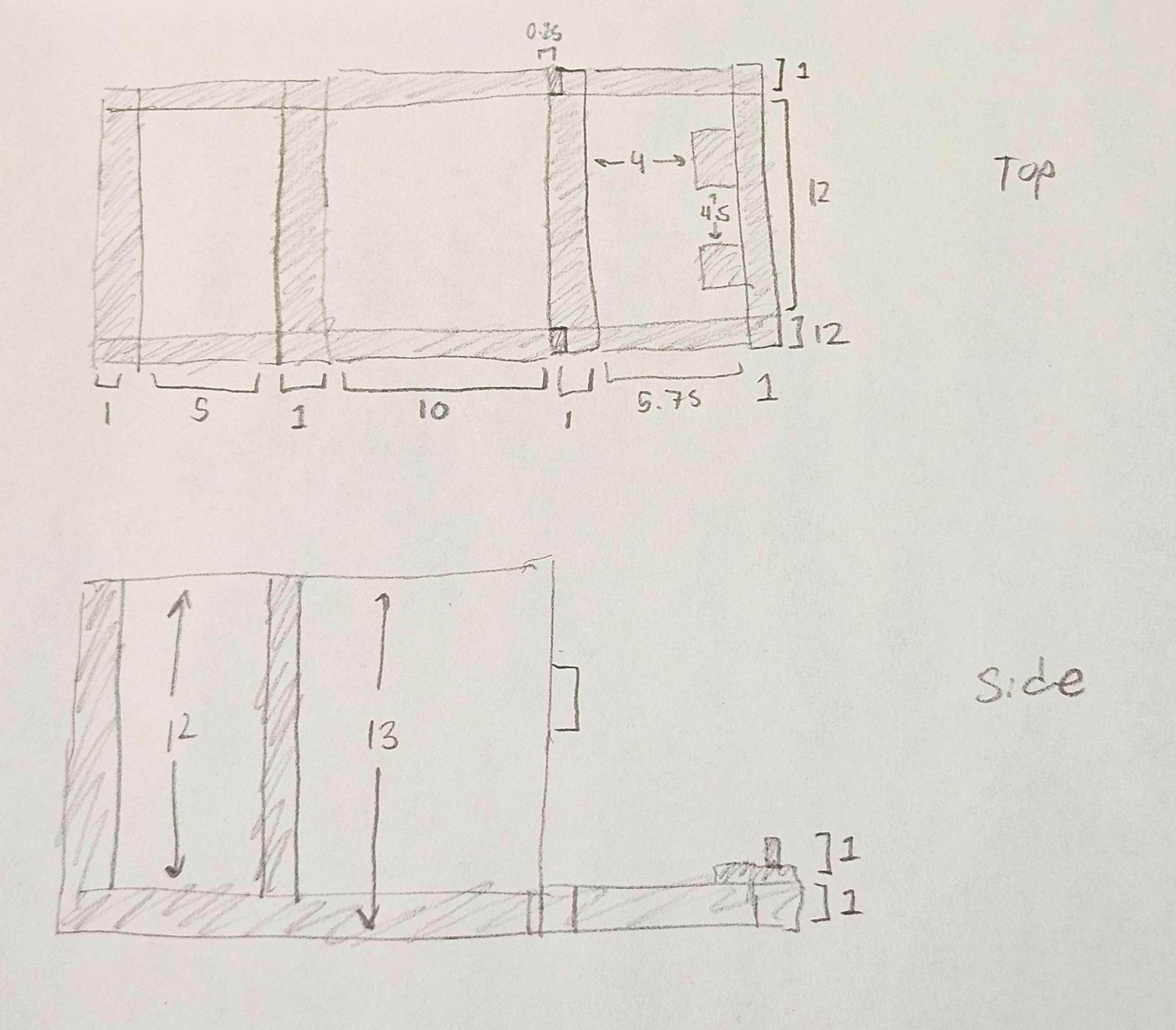
Looking at the original location of the pump mount, since the vacuum is closer to the front, the pump mount needed some adjustments to fit the same way.
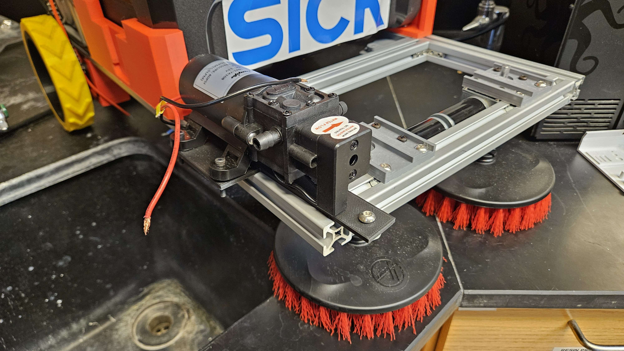
So, a new pump mount was modeled and printed.
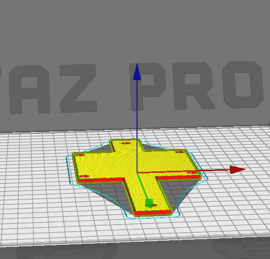
Looking at the space available, we considered which reservoirs would be appropriate:
- 12.99 x 9.49 x 2.99 inches, 7L – 32.09
- Fuel line hose
- Fuel shut off valve
- Kinda bad reviews, no female thread on tank

- 13.35 x 10.04 x 4.09 inches, 7L – 30.99
- This is package dimensions not item
- Barb?
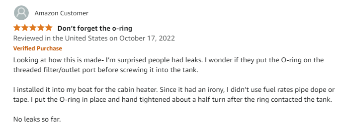
- 11.4 x 7.8 x 3.5 inches, 5L – 20.99
- This one has good reviews, though it is a little smaller
- 11.34 x 6.93 x 6.22 inches, 5.5L – 23.58
- 11.61 x 7.6 x 6.02 inches, 5.5L – 18.99
- 11.69 x 7.32 x 6.54 inches, 5.5L – 22.58
- 5.9×5.5×6.3, 2.5L – 28.99
Overall just wondering what we want to do about the location of the LIDAR and the location of the reservoir:
- Reservoir close to vacuum and LIDAR in front?
- Lidar on top of reservoir?
- Extend height of electrical board poles and mount LIDAR on top of electrical boards?
- Mount reservoir on sides of robot (maybe one on each side?) and mount LIDAR in front?
- Or any other ideas…
The team decided that the 5.5L more cube filter works at the front, with the LiDAR mounted on top.
Week 5 (Feb 3 , 2025 – Feb 9, 2025)
This week, I printed some more mounting equipment as a test
- Tube clamp – Added mounting bracket
- Motor controller mount – Widened holes for mounting screws
I noticed the filament was being very sparse when printing. This is because the wrong printer and the wrong diameter was selected in CuraLE. This is how I fixed it:
- In the prepare menu, click on the printer and Add printer
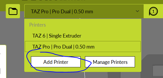
2. Add whichever printer you are using (Ours is a TAZ 6)
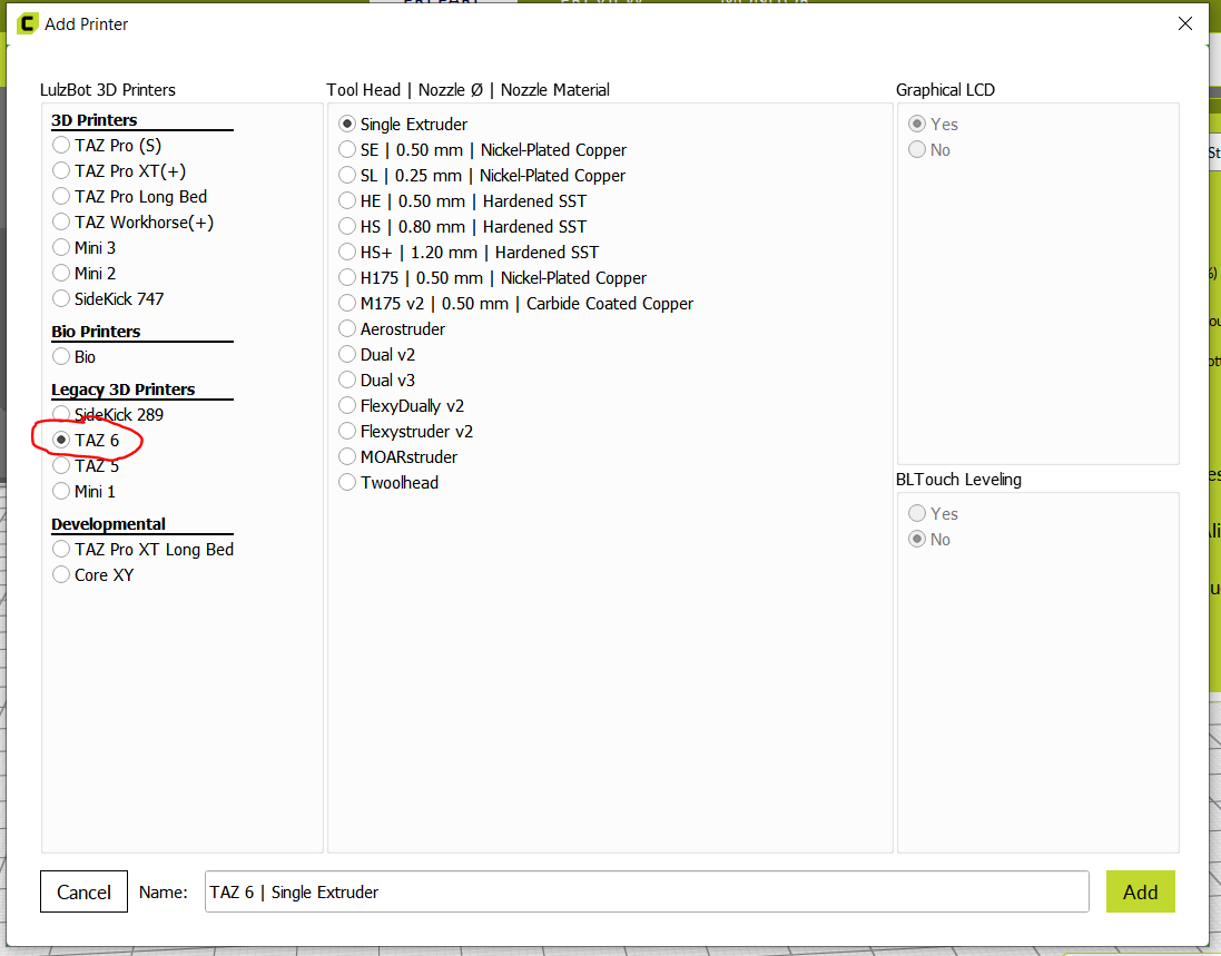
3. Then click on the printer again and select “Manage printers” instead
4. I was gonna explain how to change filament diameter by going into Material settings, but I didn’t actually end up doing this and just changing the printer seemed to fix it.
Created dupont connector between buck converter and 12v rail.
I rewired the 12-5v buck converter, the pump, scrubs, and their respective relays, and connected the 5V lines to the motor controllers. (Left pump circuit open).
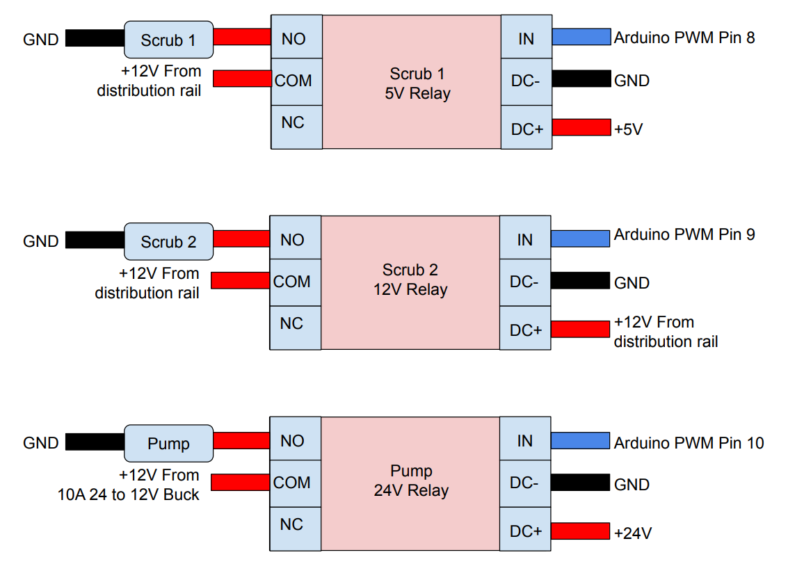
Week 6 (Feb 10, 2025 – Feb 16, 2025) (Critical Design Review)
I printed mounts for the motor controllers and secured them down. I positioned the motor controllers in a way to create more space on the bottom electrical board for the Vacuum On/Off relay. The 24V relays arrived.
I labeled the dupont connectors with colors based on the orientation they should be connected in as well as which bundle they connect to.
I used zipties to bundle together related wires and create space on the board.
I added spade connectors to the 10-12 AWG wires spanning between the top and bottom board. All of these were for the 12V rail, so no further labeling was needed. (Btw, the spade connectors are really difficult to crimp.)
I fixed the wiring for the pump relay, as it was missing the DC- wire. In addition, I added the Arduino buck to the wire nut to make disconnecting it more easily.
The top and bottom board are now fully independent, with the top board connected to the scrubs and pump.
I printed a hose mount, but connecting it to the frame would require removing the scrub bar, so I held off since it can be mounted at the same time as the pump once the LIDAR and reservoir connections are secure. The hose mount was a little bit too tight.
To do
- Re-print hose mount
- Re-design pump mount
- Check motor controller connections, then full robot test
- Concern:
- Appropriate current? Luckily got more budget approved, so can source more bucks if needed
- Tear off switch? Generate design for vac on/off switch
- Auto mode switch?
Week 7 (Feb 17, 2025 – Feb 23, 2025)
Nasi drilled holes in the board and we reconnected all components through them. We did a test to make sure the motors and scrubs could still activate.
Created a new pump mount design.
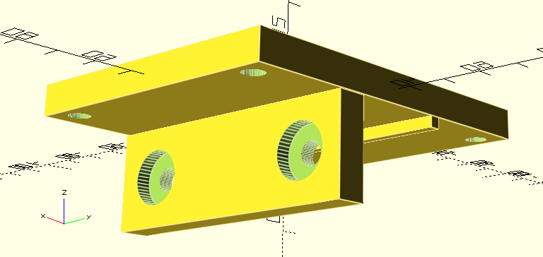
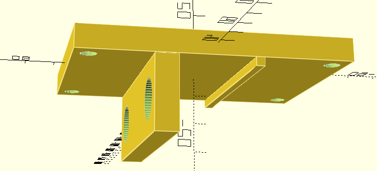
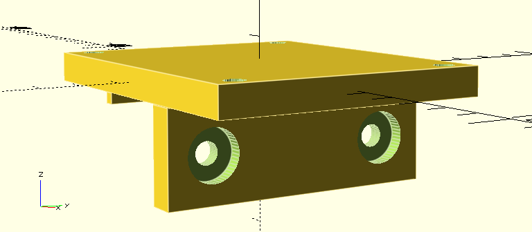
To do:
- Open up vac on/off switch
- Mount reservoir and lidar
- Mount new on/off relay + wire to arduino
- Remove front bar to attach new mount
- Cut hoses and attach nozzles
- Test pump
Concerns
- Tear off switch? Generate design for vac on/off switch
- Auto mode switch?
Week 8 (Mar 3, 2025 – Mar 9, 2025)
This week, the pump mount was printed and secured, but due to structural issues it snapped in half. A new mount was designed to increase its strength, and the pump was mounted to the front of the robot.
Upon working on the water resistant cover, Seth noticed our electrical boards were not cut precisely (whoops) and decided to remake them, as well as the battery mount. So, the majority of this week was spent re-mounting electronics onto the new boards.
In addition, our new reservoir arrived this week, but it did not have a hole for the hose connection–that needed to be drilled in.
We now have all components to assemble the robot, and just need to finish mounting everything.
I started writing an article style summary of the project. This will be worked on during the meeting on Friday as well.
- Generate design for vac on/off switch
- Types of switches https://uk.rs-online.com/web/content/discovery/ideas-and-advice/toggle-switches-guide
- Fixing sticky on off switch https://www.youtube.com/watch?v=MKxOW2G22c8
- Replacing switch https://www.youtube.com/watch?v=VQ8DVUeEOG4
- Ultimately if it’s just a single switch, it can be replaced with a NO relay, which is triggered by an IN from the arduino.
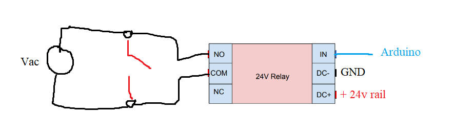
To do:
Open up vac on/off switch- Mount reservoir and lidar
Mount new on/off relay + wire to arduino- Remove front bar to attach new mount
- Cut hoses and attach nozzles
- Test pump
Concerns
- Auto mode switch? — Same as last week, though this is not in the project specs, so the robot will automatically begin to enter autonomous mode as it is turned on.
- Tear off switch? — I’m kind of worried of breaking something by taking a screwdriver to the vacuum.
Week 9 (Mar 10, 2025 – Mar 16, 2025)
This week, I re-mounted the pump mount at a different angle so it does not interfere with the reservoir mount.
I’ve been testing a few prints for mounting the hose itself, but I have not had great luck since the pump was re-positioned.
Thingiverse hose clamps
- https://www.thingiverse.com/thing:488671
- https://www.thingiverse.com/thing:1309897
- https://www.thingiverse.com/thing:806412
Maybe it can be fastened to the bottom. (Front has pump in the way, top requires removing 2 components.
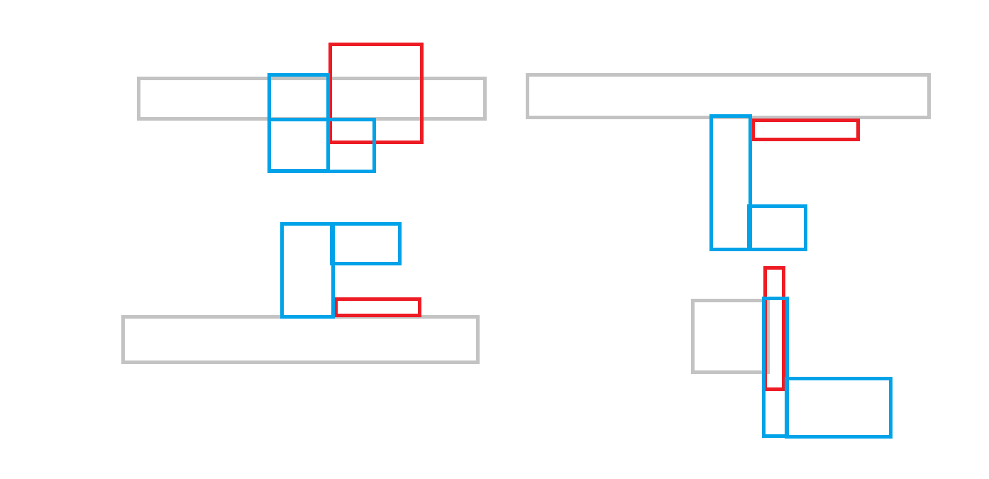
Hose can “loop” around.
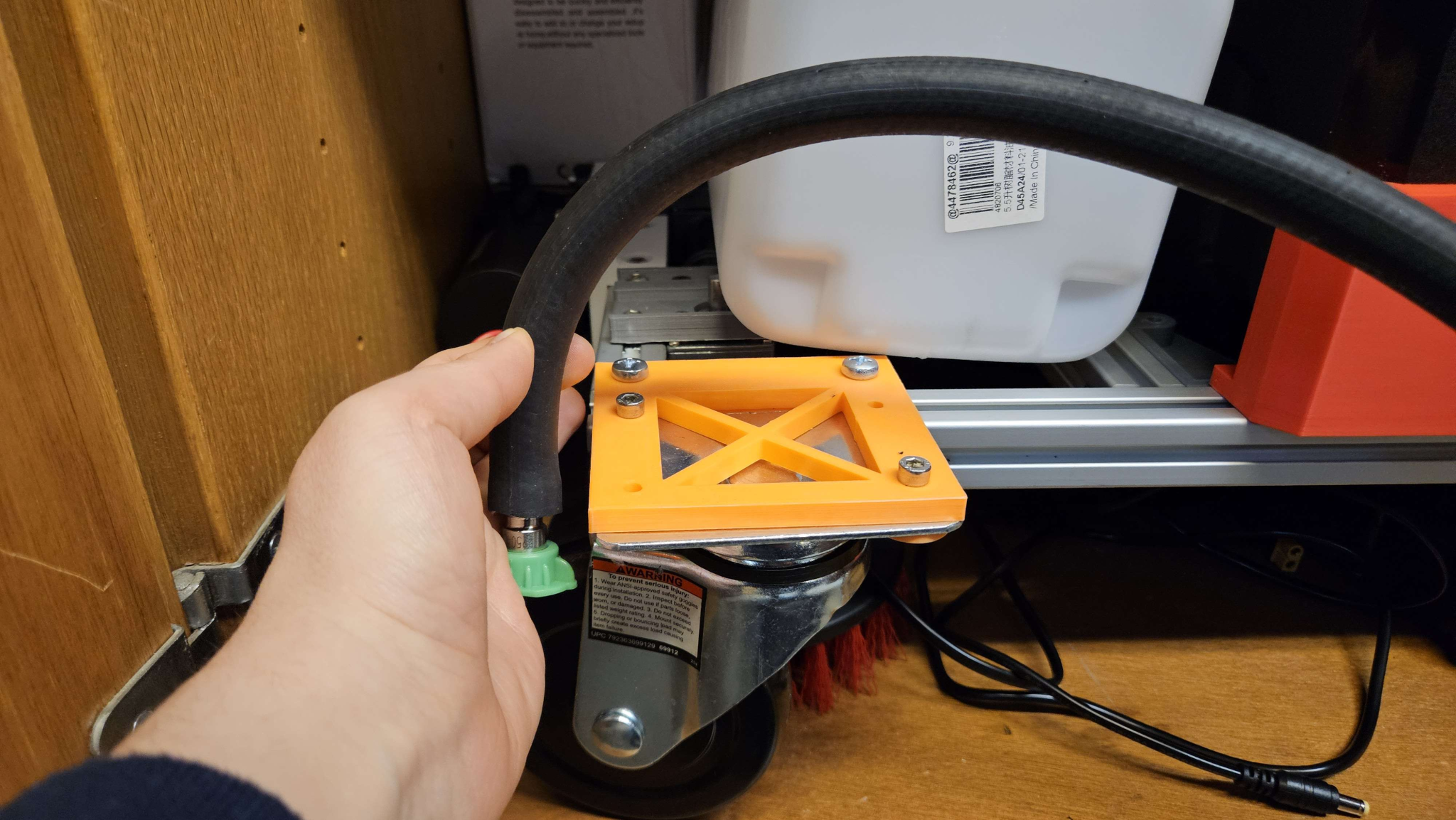
Though bending it is a bit difficult.
Maybe it can be part of the pump mount.
The hose mount was ultimately created as an addition to the pump mount. Initially it held the hose a bit too close to the ground, so a taller version of the mount was created.
To do:
- Mount hose mount
- Drill hole in clean tank
Week 10 (Mar 17, 2025 – Mar 23, 2025) – SICK video due
This week, we attached the hose mount to the robot. This holds the nozzle about 20 cm above the ground and keeps the spray clear of the pump.
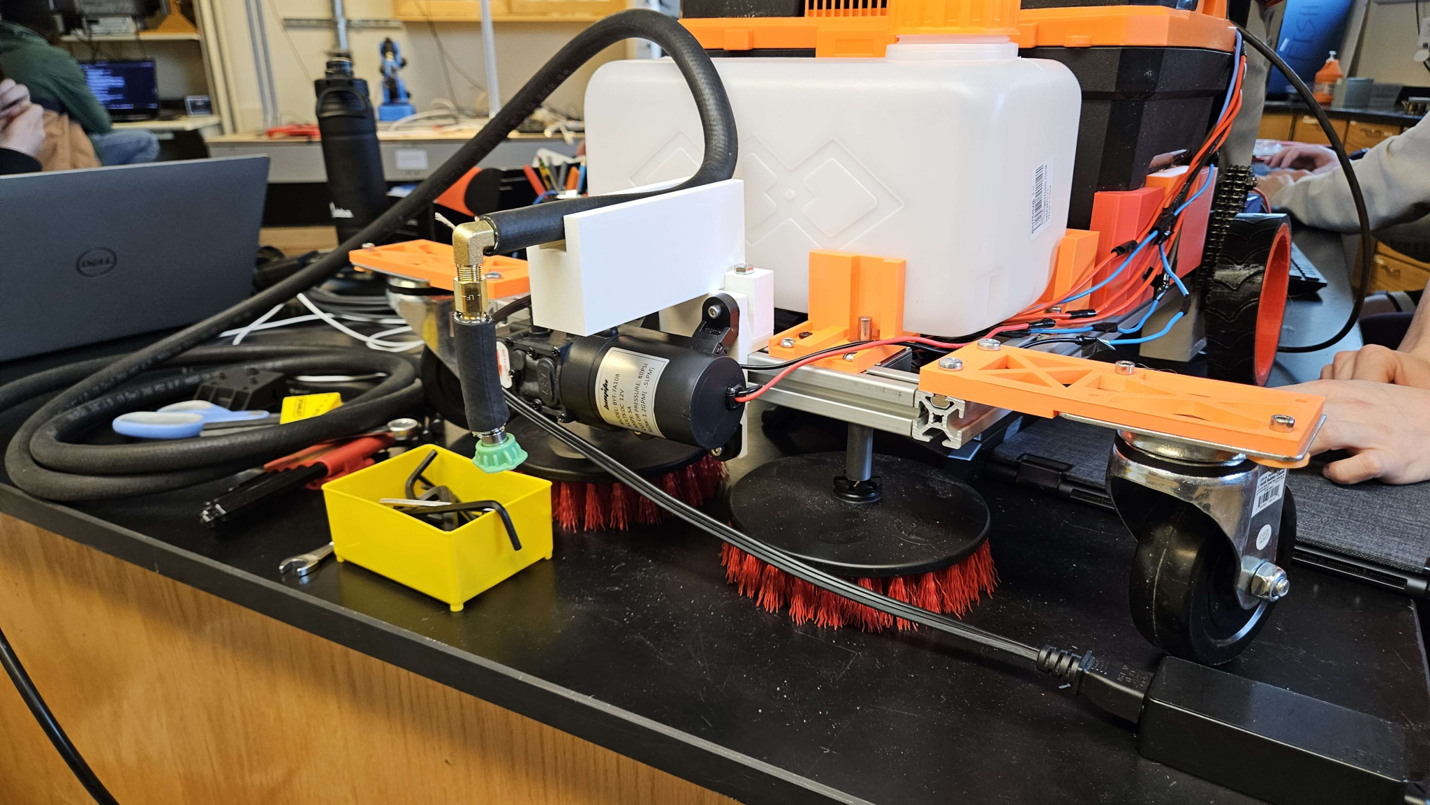
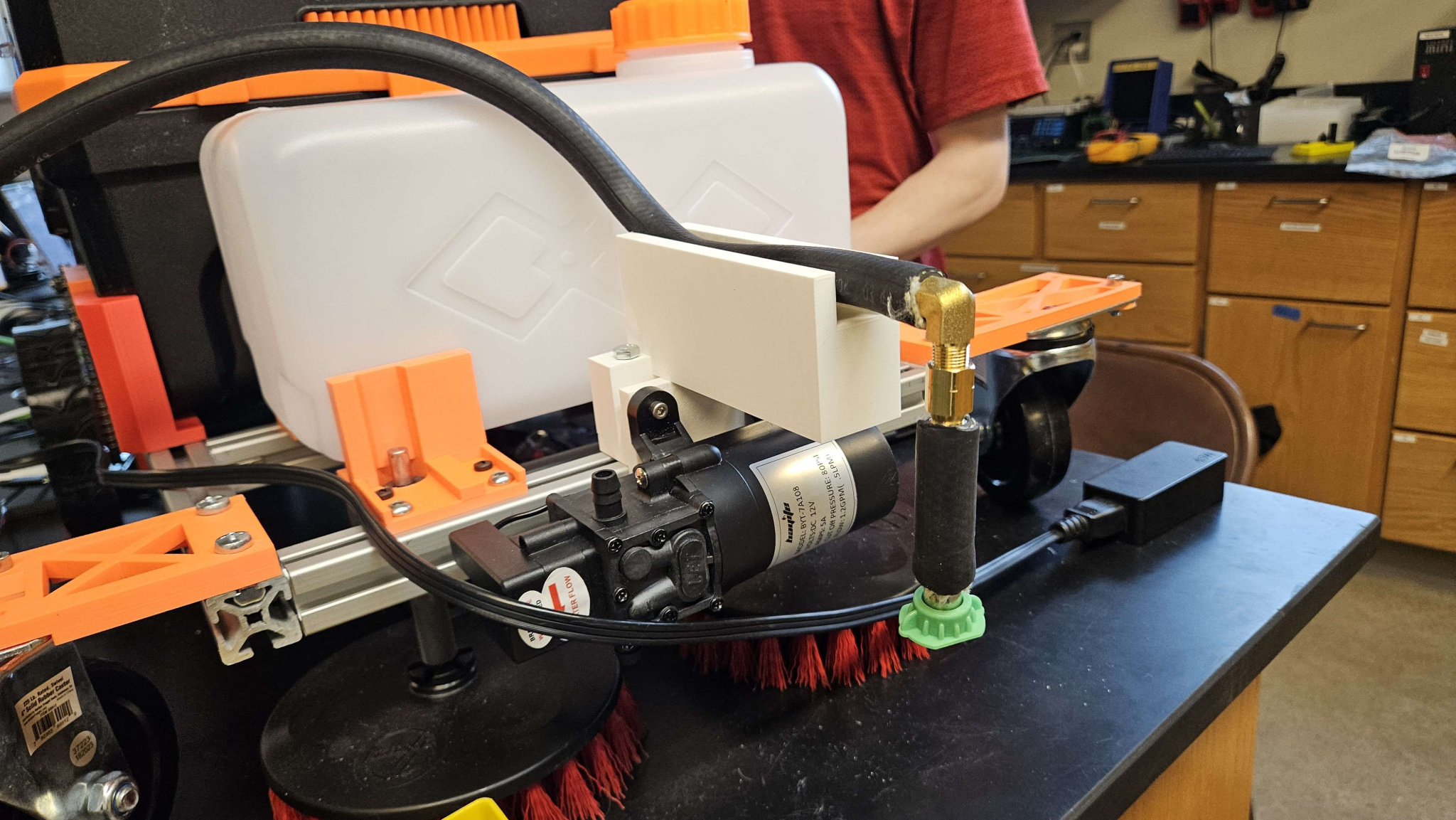
There were some setbacks due to a corrupted SD card, so our programming team had to remake a lot of code. Ultimately, we managed to create a boot file, and collect LIDAR data.
We created a code with PID control to navigate using the LIDAR, and submitted our SICK short report and video.
Things to do
- Fix drive base
- Reverse direction on one scrub
- Add scrubbing and dispensing into the auto code
- Fix squeegee
- Test with rice
- Test with vacuum
Week 11 (Mar 24, 2025 – Mar 30, 2025)
This week, we added scrubbing and dispensing to the auto code. I designed a box for the raspberry pi, but some sizes were off. A new box is being printed. We added clamps to the hose to prevent leaking, and drilled a hole for the arduino cable. After adding the squeegee mount, we programmed RC code onto the robot to test if it could drive. We hot glued a servo to the power switch and it seemed to be switching fine. However, after the glue was applied, the servo stopped working. We found a replacement and will add it next week.
Things to do:
- Replace servo
- Re print box
Week 12 (Mar 31, 2025 – Apr 6, 2025) (CHECK OFF)
This week we replaced the servo but did not use hot glue. It was not the best for switching the robot. We tested the robot in a controlled environment and found it could avoid obstacles and suction rice and water. We completed our design checkoff.
Week 13 Apr 7, 2025 – Apr 13, 2025)
This week I unscrewed 8 screws on the the bottom of the vacuum lid to reach the wires for the on/off switch. We put a relay in series with it.
We tested the relay configuration using 2 DC power supplies, one for 5V to supply power and one for 1.5V input as the signal. This worked to run the vacuum as long as the switch was in the “on” position.
Once we actually connected it to the vacuum, and drilled a hole in the side of the lid in order to route wires. I drilled a hole in the top of the electrical box and crimped connectors so the vacuum could be removed.
We noticed the relay was not switching, so I grounded the DC- on the wire nut and used a different wire for INPUT and a different pin on the arduino, as well as adjusting the code. This allowed it to work.
We noticed the vaccum still would not turn on so I removed the 8 screws to open the vacuum lid, and noticed a wire came detached from the wire nut. I stripped the wire further so that the connection could be more secure.
Finally, this allowed the vacuum to be remotely powered.
Week 14 (Apr 14, 2025 – Apr 20, 2025)