
About the Project
The KeWee Energy Meters project aims to create a series of devices and software for home energy monitoring. We seek to make affordable sensors and IoT devices that can communicate with a central or self-hosted web server for storing data. We also seek to design a website for users to access their device information and share it with others. Our project has been ongoing since January 2022, and is expected to continue for at least a year or more into the future as this project has many areas prime for growth and development.
About the Team
Evan Grahs (Computer Engineering Major, 4th Year): Website, Server, and On-Device Software Development
I develop the PHP, MySQL, JavaScript, HTML, and CSS necessary to build our website and various user interfaces. I manage a self-hosted LEMP stack (Linux, Nginx, MySQL, PHP) server for our development environment. This semester, I have been developing on-device Arduino/C++ software to handle all wireless communications and user interface components.
Justin Rish (Electrical Engineering Technology Major, 5th Year): Hardware Design and Safety
I research and design most of the physical electronics used in this project, as well as develop hardware schematics and the PCB design. Since I am currently the most familiar with the hardware design of the KeWee meter, I help with testing the device when possible.
Liam Cacioppo (Computer Engineering Major, 4th Year): Embedded Software Development
I develop the embedded Arduino code that processes data from the sensors. The Arduino code is written in the native Arduino Coding Language and C++. I also perform testing on the equipment to ensure quality of the measurements. This semester, I have been designing new libraries for the current and voltage sensing and programming a new meter measurement file to calculate apparent and real power.
Sierra Derusha (Electrical Engineering Technology Major, 4th year): Electrical Research and Equipment Testing
I research and integrate electrical and mathematical concepts into our project design. I also test the implementation of these concepts to validate their efficacy and accuracy while ensuring safe operation. I assess the test results and information gathered to further advance the functionality of the final product.
Goals for this Semester
On-Device Software Goals
- The device will have software libraries for converting raw sensor data into meaningful data measurements.
- Assignee: Liam Cacioppo
- Status: Completed
- The API Documentation for the Current and Voltage Sensor libraries are available embedded below or at the following links: Current Sensor API, Voltage Sensor API
- The server and device will exchange commands and data through a documented API.
- Assignee: Evan Grahs
- Status: Complete
- The Network Communication API for the Device / Server communication is attached below and available at the following link: KeWee Network API
- The server and device web-based interfaces will have a unified design language.
- Assignee: Evan Grahs
- Status: Complete
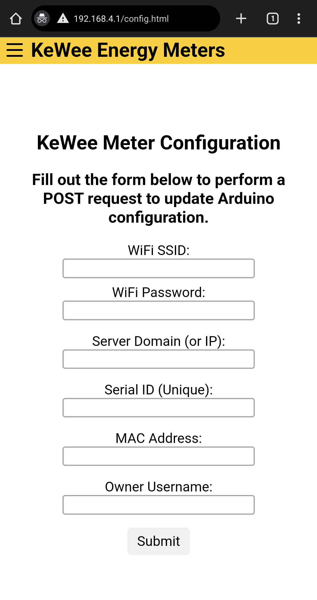
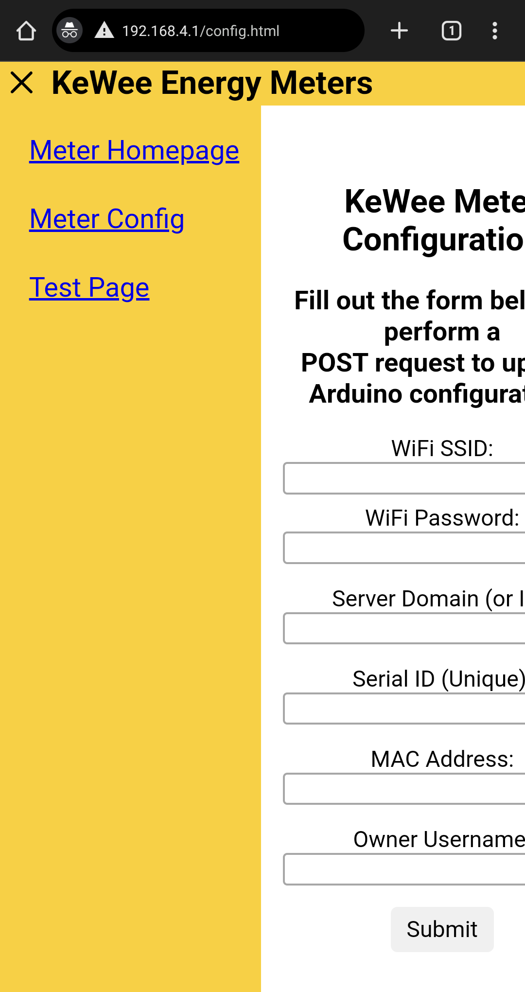
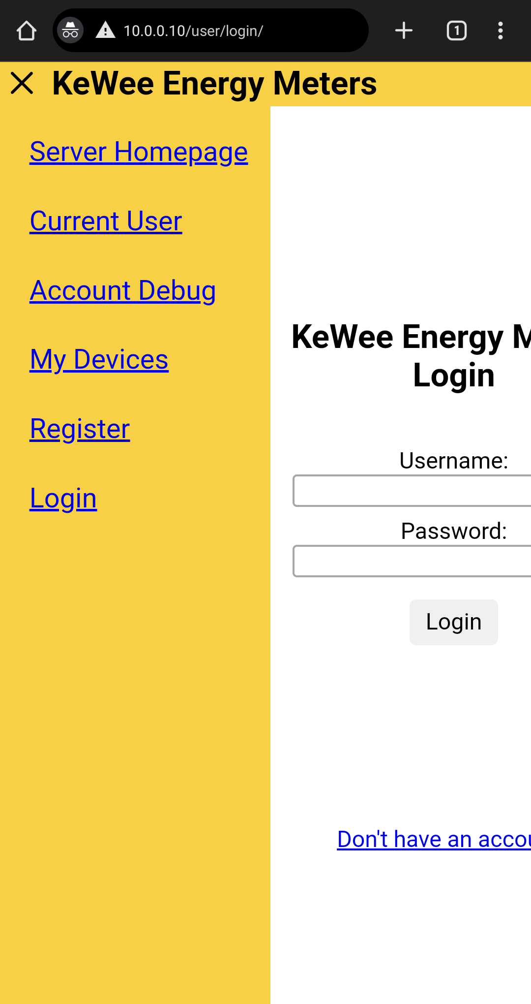
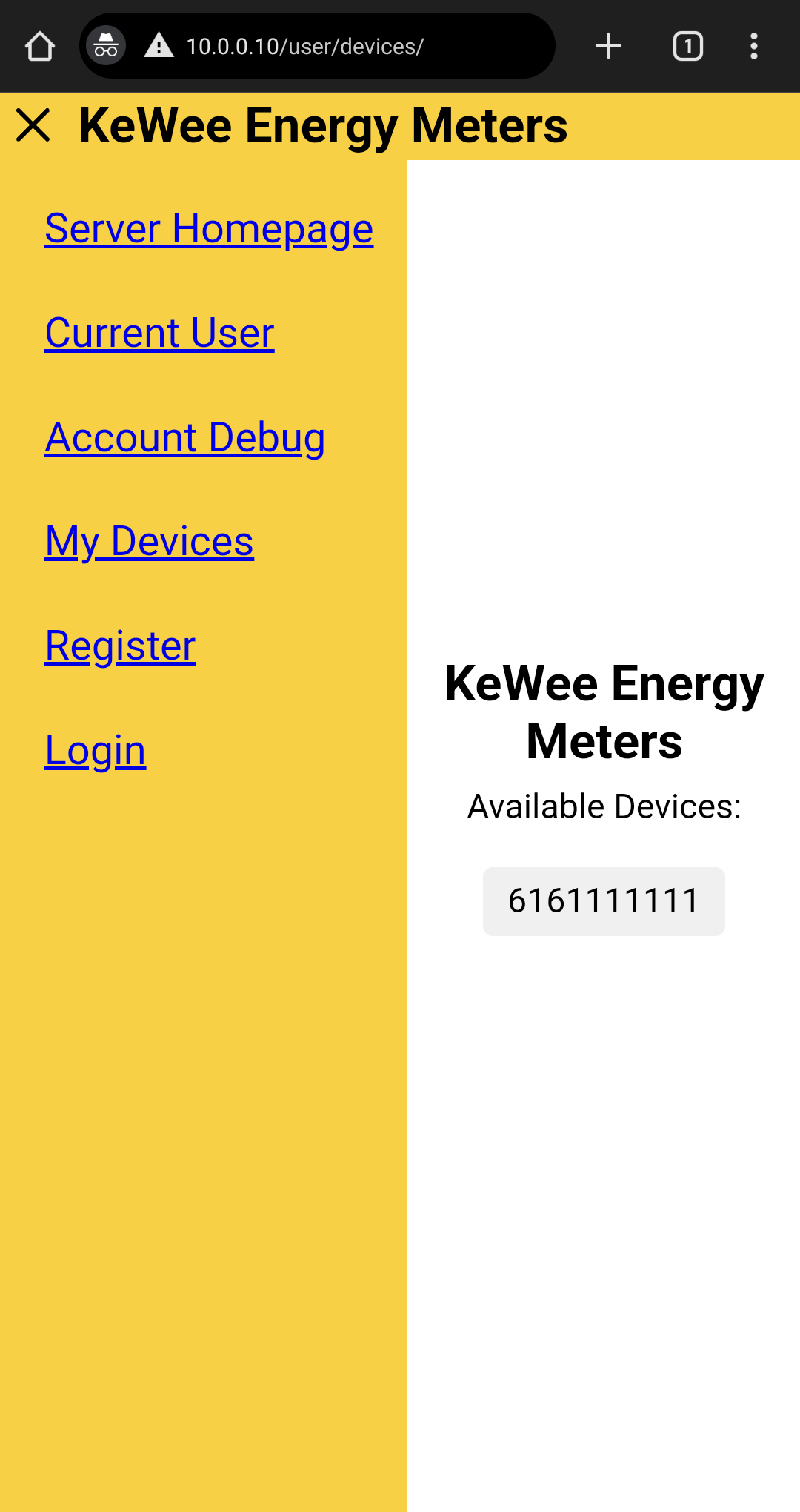
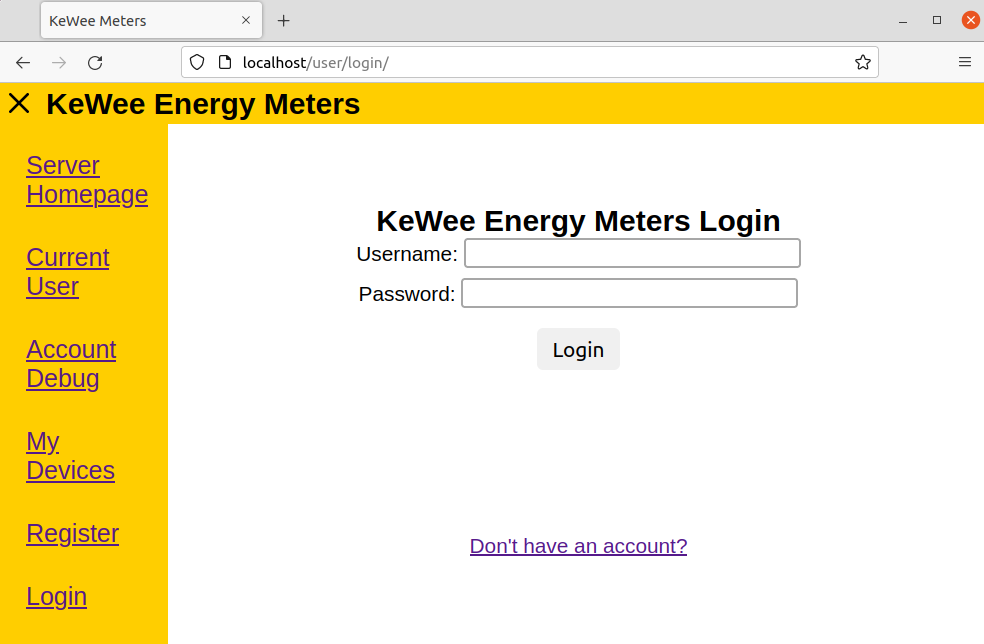
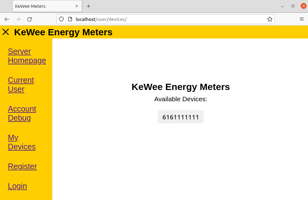
- All existing web pages, both server-side and meter-side, have been updated with a new look and layout in the style of a more modern web application with menus and navigation features. Existing elements of pages have been given a unified CSS library to style off of. See the image gallery below for samples of this UI running on both the server (localhost / 10.0.0.1) and the meter (192.168.4.1) on a variety of screen types.
Hardware Goals
- The entire device will have design files compatible with and editable from free and open-source software.
- Assignee: Sierra Derusha, Justin Rish
- Status: Completed
- Arduino code and KiCAD schematic and board are provided at our OSF Repository (The “Hardware Files” directory in particular).
- The device will be capable of deriving values including power factor and wattage.
- Assignees: Sierra Derusha, Liam Cacioppo
- Status: Incomplete
- For in-depth information on this goal, please see the document embedded below or view it linked here.
- There will be a higher rate of reliability within our voltage and current data readings in reference to previous semesters’ work.
- Assignees: Liam Cacioppo, Sierra Derusha
- Status: Incomplete
- For in-depth information on this goal, please see the document embedded below or view it linked here.
- The device will have some custom-designed PCBs constructed for reduction of internal component sizes.
- Assignee: Justin Rish
- Status: Partially completed
- Unfortunately, the PCB design did not appear to work. Multiple redesigns of the board led to not enough time to thoroughly test it for issues, but one problem appears to be related to a KiCAD footprint. The optocoupler footprint in KiCAD appears to be have pins 1 and 2 reversed from the pinout shown on the component’s datasheet. This leads to the diode inside the optocoupler always being open circuit, therefore disabling the voltage sensing in the circuit. The current sensor portion of the circuit also did not work for an unknown reason. The board takes 120V, 1A current with no damage to the board, but the voltage outputs of the ACS725 and the optocoupler are not correct.
- Design and construct an enclosure for the device with adequate user safety considerations.
- Assignee: Justin Rish
- Status: Incomplete
- The PCB went through multiple redesigns throughout the Fall 2023 semester, which delayed work on the enclosure. The board will still have to be redesigned again for three reasons, which could require an enclosure redesign for each PCB redesign. The first reason is to accommodate high power (20A @ 120V) and allow a direct plug from a duplex wall socket into the KeWee Meter PCB. The second reason is that further research could still be done on selecting a relay. The relay that we have currently selected will work for the KeWee meter without being excessively large, but other home power meter devices manage to control their circuit in a small form factor that is barely possible with our current 30A relay. Further semesters will require more looking into this matter. The third reason is that the current design requires a micro-USB connection to power the Arduino Nano, which will not be viable in the final design. The circuit will need to be changed to supply power to the Arduino Nano using the 120V AC source from the duplex outlet.
Exploring Alternative Solutions
A standard Arduino Uno, while quite capable, posed a few situations that were sub-optimal as we shifted to targeting the consumer market with our meter. First off, the board has a considerably large footprint, and that is without any additional sensing circuitry. Second, the board lacks in-built connectivity features such as Wi-Fi that are crucial to an IoT / Smart Home product. While connectivity can be added to the Uno, it requires an additional module and significant programming integration to work, as well as additional cost per device. Seeking to solve these problems, a convenient solution was found: The Arduino Nano RP2040 Connect. This specific model of Arduino is filled to the brim with useful IoT features, from a dual-core RP2040 microcontroller to a u-blox NINA Wi-Fi module, all in a similarly priced board compared to the Uno, and in a much smaller board footprint. This made it the ideal device to be the brain of our meter.
Changing to the Nano offered great functionality to the server side of the project but required a complete redesign of the system on the hardware side. It allows the device to be much more compact as the greatest benefit to the hardware side of the project. The main difficulty is changing from the UNO’s 5V ADC to the Nano’s 3.3V ADC. Almost all of the previous components were therefore rendered useless in the new KeWee meter PCB design, so research had to be done on what new components to select.
At the end of the previous semester, we had simply used pre-built boards to measure voltage and current, but in order to compactify the KeWee meter device, we thought it would be good to put all of the components on one board. Designing a KiCAD schematic and board file for this using raw components instead of pre-built PCBs also allows for the project to be more Open Source because it does not depend on pre-built boards with rather little documentation.
Another alternative solution for the PCB is regarding the selection of component mounting methods. Initially, we opted to select surface mount components so that the KeWee meter PCB can be more compact, but upon receiving the parts were advised that attaching such small parts may make it difficult to replicate the project, and therefore not very open source. This required a change to some through-hole components, and another redesign of the PCB footprints.
A Relay was selected for the KeWee meter board, but it was found that the only relay options that support 120VAC at 20A are rather large. Larger than smart plugs tend to be, so there must be an alternative solution to compactify a relay for controlling the device. This potential for an alternative was only realized at the end of this semester, so further research will be pushed to a later semester on the project.
The old design used a third-party open-source library for the ACS712 current sensor. Unfortunately, this library is no longer available online. It also did not sample in a non-blocking manner which we desired so that we could have greater flexibility in timing readings and web server operations. Furthermore, this library is not compatible with the ACS725 so we decided to write our own current library.
Design Constraints
The KeWee Energy Meter is being developed with the intent of being distributed to many people as a home power monitoring tool. As a result of this target demographic, the design must factor in constraints to make the product more appealing to general audiences and consumers. This includes keeping the cost of the meter low so that more people can afford it. The meter should also be small so that the device is less bulky, as people tend to prefer more compact devices over needlessly large ones. As the KeWee Meter is being designed in the Open-Source Hardware Enterprise, all designs must also be completely open source. This way, anyone can review and build on our design, and access all pertinent design files through open source software and tools.
Hardware Safety Considerations
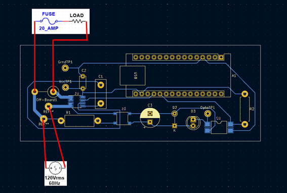
- We included a fuse in the KeWee meter current sensor loop. At the moment, this fuse is not on the board so it should be connected between the off-board nodes by the Vcc node on the PCB. Location is shown in the “Steps to replicate hardware” section.
- PCB etching reduces risk of arcs on the PCB. Since the board is reading direct 120V from a wall outlet, the KeWee meter PCB we fabricated is etched.
- For testing the equipment, a Variac is important for allowing users to test with low AC voltage before using higher voltages such as 120V. Many Variacs should also include a replaceable fuse, such as the one we have been using.
- Insulated exposed leads with electrical tape or heat shrink on low temperature connections. Higher temperature connections in the current sensor loop of the circuit should eventually be connected with 12 AWG fiberglass-insulated wire, but the current board is not yet designed for high power draw.
- The enclosure should be capable of dissipating substantial amounts of heat. The temperature in the enclosure should not get high enough to cause potential damage to the components or the enclosure material, and should remain low enough that the electrical components in the meter act in their specified temperature ranges.
Steps to Replicate this Project
Source Files
All of our published source files* are available at: https://osf.io/9pn2d
*All the files you need to replicate the project are available at the OSF Repository. Some other files exist, but are not intended for use in replicating the project.
Active in-development files are located at: https://github.com/evangrahs/kewee-meters
Hardware test files are available at: https://github.com/ljcaciop/kewee-hardware
Replication Procedure
How to Replicate the Server Software
The server software, despite most HTML / PHP pages having been updated with the new user interface, still has largely the same setup process as in semesters prior. If you have a self-hosted instance, besides doing your own Nginx, MySQL, PHP, and OS updates, all you need to do is download an updated copy of the root WWW folder from the OSF Repository and overwrite the files currently in your WWW directory. Note that if you have existing meters, be careful, new database structure changes have been made that might cause issues or data loss. Always make a backup before attempting any upgrades. For those looking to set up a self-hosted server for the first time, the instructions are included below.
(Click to Expand) Instructions for setting up a self-hosted LEMP stack server.
- Set up a computer or virtual machine with a Linux distribution of your choosing (we recommend an LTS branch of Ubuntu). Alternatively, find a hosting provider for a LEMP stack server.
- Install Nginx, MySQL, and PHP on that system.
- We recommend following a guide based on the most recent LTS version of Ubuntu.
- At the time of writing, Ubuntu 22.04 LTS can be configured following the guide linked in the Server Resources section.
- As the last part of setting up the LEMP stack, create a MySQL database and keep track of the name for use later (when in the mysql terminal, type “CREATE DATABASE <insert database name>;”).
- Load the contents of “WWW Root Directory” into “/var/www/” and follow the article in how to configure Nginx to appropriately access this directory.
- The site name is just for Nginx to be able to reference, it is not actually changing the published domain (which is not covered by this tutorial, we only operate within a local network at the time of writing.)
- The site name is just for Nginx to be able to reference, it is not actually changing the published domain (which is not covered by this tutorial, we only operate within a local network at the time of writing.)
- Load the contents of “Database Creation Scripts” into an easily accessible directory on your system. Make sure this directory is not published. We recommend just placing it in your user account’s desktop directory.
- Modify the “Create_User_MYSQLTestUser.sql” file to replace any redacted data with the relevant credentials you’d like to have for your new database.
- If the command structure / meaning of items is unclear, please reference a tutorial on SQL. We highly recommend W3Schools.com and link to them below.
- If the command structure / meaning of items is unclear, please reference a tutorial on SQL. We highly recommend W3Schools.com and link to them below.
- Modify the “/var/www/libraries/security/kewee_credentials.php” to contain the credentials created in the last step.
- Please note the warnings in these files, this is not an ideal security practice and should be replaced by some better method for allowing local scripts to access a database.
- Please note the warnings in these files, this is not an ideal security practice and should be replaced by some better method for allowing local scripts to access a database.
- Modify the “/var/www/libraries/security/kewee_crypt.php” to contain a password hashing algorithm of your choice.
- If you are unsure of the options available to you, please see the linked PHP Documentation for more information regarding the password_hash() and password_verify() functions.
- If you are unsure of the options available to you, please see the linked PHP Documentation for more information regarding the password_hash() and password_verify() functions.
- After connecting to your newly created MySQL database from a Linux terminal (“mysql”, then “connect <insert database name>;”), use the “source” command (type “help” once in MySQL for more info) to execute the three “Create_<table/user/etc>.sql” files from the “Database Creation Scripts” directory. These will create the “Users” and “Devices” tables, as well as allow all scripts to access the database with the variables in “kewee_credentials.php”.
- Now, you should be ready to connect! The server will be hosted at http://localhost or whatever your LAN IP address is.
- Note, before port forwarding and publicly hosting your server, you should configure SSL and only accept HTTPS connections to ensure data is adequately encrypted in transit.
- Note, before port forwarding and publicly hosting your server, you should configure SSL and only accept HTTPS connections to ensure data is adequately encrypted in transit.
How to Replicate the Arduino Software
Additional Libraries Required: https://github.com/khoih-prog/LittleFS_Mbed_RP2040
Recommended IDE: Arduino IDE 2.X.X from https://www.arduino.cc/en/software
After installing the additional libraries in the Arduino IDE, download the “OSHE_KeWee_Arduino_23H2” folder from the OSF Repository and extract the ZIP, keeping the folder name “OSHE_KeWee_Arduino_23H2”. Then, open the OSHE_KeWee_Arduino_23H2.ino file using the Arduino IDE, and compile/upload the code to a connected Arduino Nano RP2040 Connect via USB.
In case you wish to understand the inner workings of the source code, see the “Resources Used/Recommended > For Arduino Software & For General Programming” sections for a selection of the most helpful resources the authors of the majority of the project source code (Evan Grahs & Liam Cacioppo) use and recommend. For more information about how to use and interact with the meter after uploading the code, continue reading this section for a general overview of operations (which remains similar to previous semesters).
(Click to Expand) Explanation of what the Arduino is doing when booted with OSHE_KeWee_Arduino_23H2.ino
When the Arduino reboots after the code is uploaded to it from the Arduino IDE (or after any subsequent boot, you don’t need to upload the code every reboot, only after modifications), it will enter a waiting loop until you open the Serial Monitor in the Arduino IDE (or an equivalent monitoring application). Once connected, it will print a large amount of debugging information, detailing all the ongoing operations. First, the code initializes all relevant devices/packages: Sensors, Storage, WiFi, and the HTTP Server. Once this has completed, it enters the loop() function. This function’s behavior heavily depends on saved state information, such as saved WiFi credentials, visible WiFi Networks, account details, access tokens, and more. If you just booted the Arduino for the first time, then your Arduino will start the default setup WiFi Access Point (“KeWee Meters Setup”). Using the credentials found in the main sketch source file OSHE_KeWee_Arduino_23H2.ino, you can connect any device with a web browser. Then, access the following URL: “http://192.168.4.1” This will have a hyperlink to /config.html, the actual setup page where you can specify the WiFi network, you’d like the device to join, as well as the account and server to register with (assuming you are self-hosting the server since our instance is not public yet). Once you set the configuration, the Arduino will attempt to connect to the given network, and on success, attempt to register with the server to obtain an Authentication Token that it can proceed to use to upload data on a regular interval. If registration succeeds, and the token is saved correctly, your meter will now be uploading data measurements to the server you specified.
How to Replicate the Hardware
- Purchase Hardware listed in the Bill of Materials.
- Only one of each hardware component is required.
- Download the PCB_Fabrication_Files.zip file from the OSF Repository.
- Fabricate or order the KeWee Meter PCB.
- The board should be etched to prevent arcs since the board contains 120V AC through the current sensor loop.
- Solder the components onto the PCB.
- The current version of the PCB is only rated for 3 Amps.
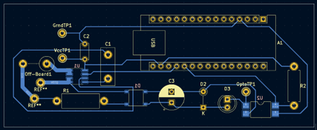
- The “Off-Board” pins are an open connection to allow the placement of a fuse, relay, etc. off of the PCB. Future plans may place these components on the enclosure rather than the PCB. Diagram of the current off-board connections is shown below.
- Install Arduino IDE or desired development environment.
- Plug in Arduino Nano to PC and confirm that the IDE recognizes the device.
- Upload the desired version of the Kewee Meters code to your Kewee Meter.
- Note that the new hardware functionality is still being developed and has not been integrated with server functionality. The new hardware functionality is available in a different repository called “kewee-hardware” and is available at the GitHub link in the above section “Steps to Replicate this Project”.
Resources Used/Recommended
For Arduino Software
- Arduino IDE is great for users that are already familiar with it. It also has a very helpful serial plotter in addition to its serial monitor.
- VSCode with the official Arduino Extension allows you to use all of your favorite debugging tools in VSCode and do everything the Arduino IDE lets you do. This is highly recommended for editing code as it allows you to use extensions or tools that you are already familiar with. To add this extension, open VSCode and open the extensions tab. Search for the Arduino Extension and click on “install”. It is also available at this link: https://marketplace.visualstudio.com/items?itemName=vsciot-vscode.vscode-arduino
For Hardware
| Description | Link |
|---|---|
| ACS725 Datasheet | https://www.allegromicro.com/-/media/files/datasheets/acs725-datasheet.pdf |
| Arduino IDE | https://support.arduino.cc/hc/en-us/articles/360019833020-Download-and-install-Arduino-IDE |
| VSCode | https://code.visualstudio.com/ |
| Arduino Extension | https://marketplace.visualstudio.com/items?itemName=vsciot-vscode.vscode-arduino |
| Arduino Nano RP2040 Connect Datasheet | https://docs.arduino.cc/static/42ff80e3d99d80a1e04c971ee167a288/ABX00053-datasheet.pdf |
| KiCAD PCB File Generation Guide | https://jlcpcb.com/help/article/16-How-to-generate-Gerber-and-Drill-files-in-KiCad-6 |
For Server Setup
| Description | Links |
|---|---|
| Ubuntu installation pages, you can choose the server edition if you do not want a GUI on the system you use as a server. Also, a MakeUseOf article explaining the difference. | https://ubuntu.com/download/desktop https://ubuntu.com/download/server https://www.makeuseof.com/tag/difference-ubuntu-desktop-ubuntu-server/ |
| Rufus is a tool that can help make a bootable USB for installing a Linux distribution of your choice. | https://rufus.ie |
| DigitalOcean is a great resource for setting up a self-hosted environment. Linked is an article for setting up a LEMP stack on Ubuntu 22.04 LTS. | https://www.digitalocean.com/community/tutorials/how-to-install-linux-nginx-mysql-php-lemp-stack-on-ubuntu-22-04 |
| The PHP Documentation is an important resource for understanding the PHP code used in this project and has nearly everything about the language covered in detail. | https://www.php.net/manual/en/index.php |
For General Programming
Bill of Materials
| Component | Part/Identification Number | Price Paid This Semester |
|---|---|---|
| Arduino Nano RP2040 Connect | ABX00053 | $29.40 |
| Test Point x9 | 36-5002-ND | $3.42 |
| 1W 62K Resistor TH x10 | 13-RSF100JB-73-62K-ND | $2.54 |
| .25W 47K Resistor TH x10 | S47KQCT-ND | $0.58 |
| 3.3V Zener Diode TH x10 | 1N5226BFSCT-ND | $1.35 |
| 0.1µF Capacitor TH x10 | 56-K101J10C0GF5UH5CT-ND | $1.47 |
| 1µF Capacitor TH x10 | BC2974-ND | $1.75 |
| 100µF Capacitor TH x5 | 1189-1659-1-ND | $1.70 |
| 20A Fuse x5 | 0314020.HXP | $8.60 |
| Fuse Holder x3 | 03540601ZXGY | $4.35 |
| 30A Current Sensor x4 | ACS725LLCTR-30AB-T | $17.44 |
| Bridge Rectifier x5 | ABS6 | $1.55 |
| Optocoupler x10 | LTV-817S-TA1 | $2.63 |
| 30A 120VAC Relay x2 | T92P7A22-120 | $22.90 |
| KeWee Meter PCB x3 | $40.35 |
Total Expenditures (Fall 2023 Semester): $140.03