
Written by Joey Klapkowski and Lindsey Manhart
Overview
The Lasersaur is an open source CNC laser cutter. This laser cutter has been inoperable for a long time, and the goal of this project is to make it safe and ready to use. The work done this semester was primarily focused on ensuring that the laser will work and making the machine safer to use, as seen in Fig. 1 by the functional requirements mainly focusing on how the laser can be made safe.
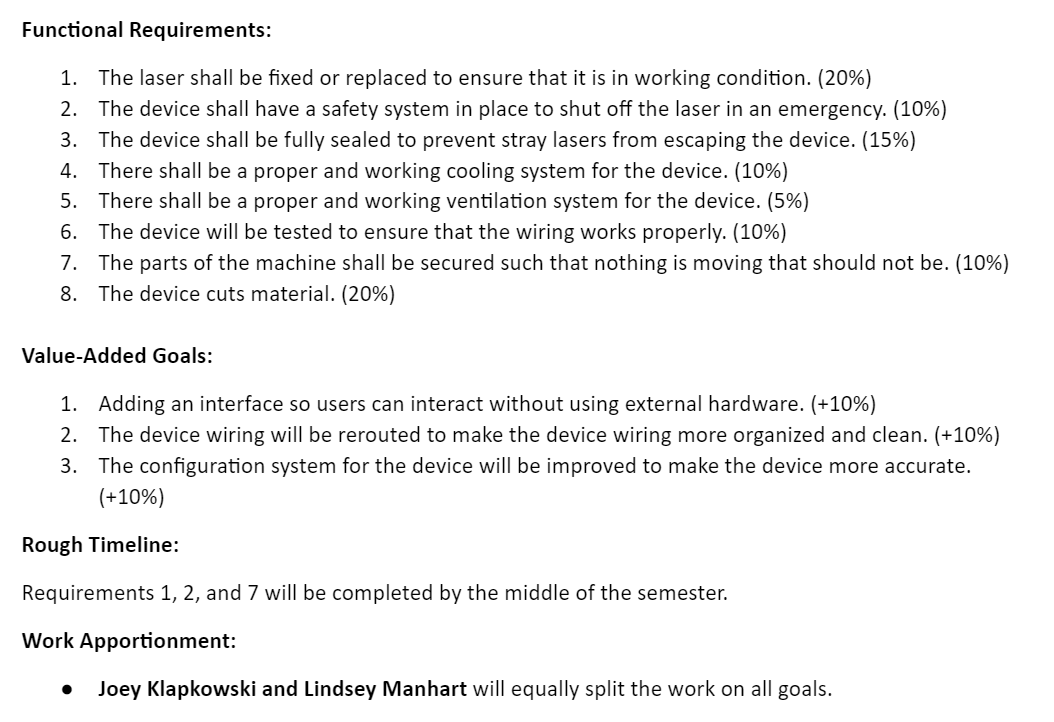
Fig. 1 – Functional Requirements and Value-Added Goals
This report will explain the work done to achieve each of the functional requirements except for goals 4 and 8. For goal number 4, significant work was not needed for the water cooler as it was already functioning properly. For goal number 8, it was not completed properly. The main roadblock to that goal was the laser alignment. The current process used to align the laser did not align it in a way that was safe enough to perform test cuts. Future work on the laser cutter will focus on this process. This failure also meant that there was not enough time to work on the value-added goals. This is ultimately acceptable, as these goals would improve the Lasersaur, but are not necessary to making it operational.
Getting the Laser to Fire
The first goal for this semester was to make the laser operable. Prior to this semester the laser would not fire when given the command. This could have been due to electrical issues or the laser expiring and leaking CO2. To check if the laser was leaking, a fire test was attempted while listening for a popping noise. If this happened without the laser turning on, it would mean that the laser was leaking CO2 [1]. This did not happen, which meant that the laser was working and there was some other issue. This meant that there was some problem with the wiring.
Checking the power supply manual from the OSF page showed that the wiring had been done incorrectly. The power supply has 6 pins which need specific voltages to allow the laser to fire. As seen in Fig. 2, these pins are the 5V pin, which gets set by the supply, the high trigger and low trigger pins which can be set to determine the differential voltage being checked, the water protection which needs to be set to 0V, the ground pin which sets the 0V point, and the power in which needs to be set to 5V [2].
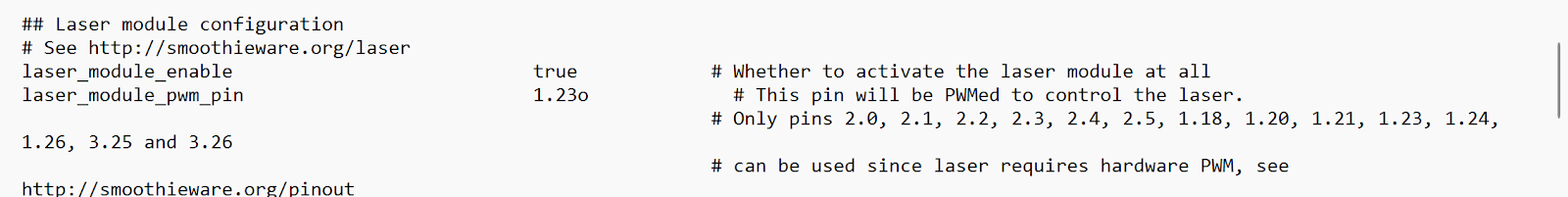
Fig. 2 – Power supply pin diagram [2]
The original wiring did not follow this scheme. As seen in Fig. 3, it only connected the 5V pin to the input, the ground pin to the Smoothieboard ground, and the low trigger to the Smoothieboard control to modulate between 3.3V for off and 0V for on. This failed to provide proper input to the water protection and maintained some nonzero voltage difference between the low trigger and input voltage. This prevented the laser from firing while also ensuring that if the water protection was connected, the laser would fire uncontrollably.
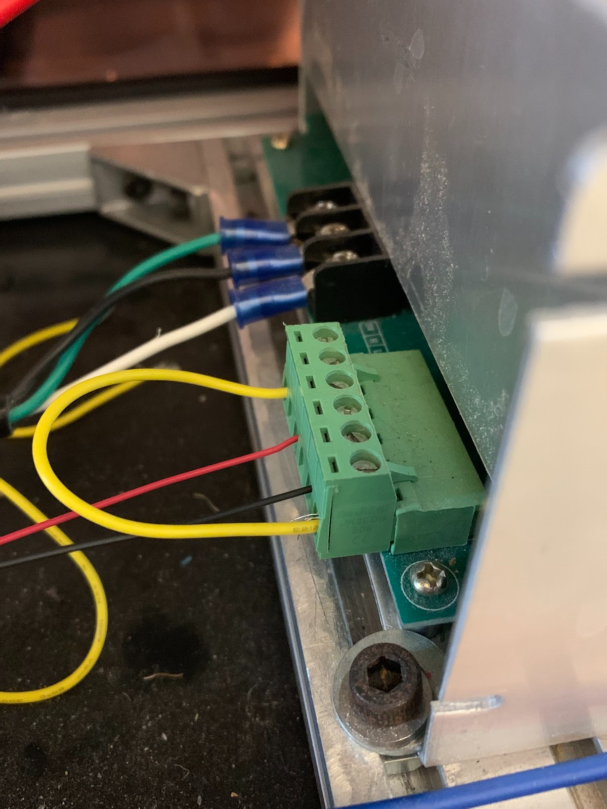
Fig. 3 – Old Laser Wiring
These problems needed to be addressed in order to control the laser. The first step was adding in the water protection relay with a DIN pin connector. The “Common” wire H1 was connected to the power supply’s water protection pin, the “Off” wire H2 was connected to 5V, and the “On” wire H3 was connected to ground [3]. This allows the water protection pin to be forced to ground and allow the laser to work only if the cooler is working properly. The other change made was wiring the low trigger to ground, the Smoothieboard control to the input voltage, and changing the Smoothieboard configuration file to modulate the control wire from 0V for off to 3.3V for on. This prevents uncontrolled fires from happening by keeping the input voltage at the base of the low trigger instead of at an offset as it was previously.
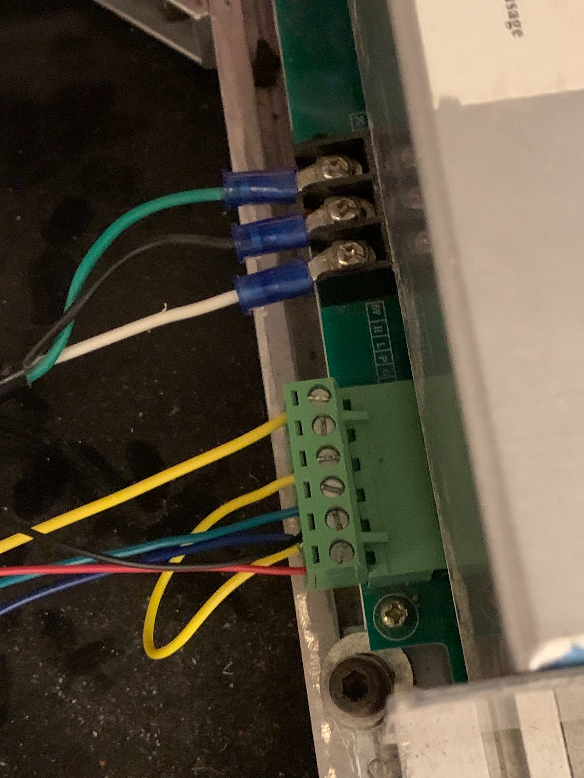
Fig. 4 – New Laser Wiring
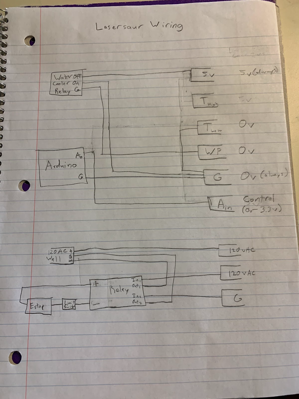
Fig. 5 – Full Wiring Schematic
Fig. 6 – Changed Smoothieboard Configuration File
Updating the Safety Relay
The second goal was to have Lasersaur to have a safety system and have the laser be shut off in the case of an emergency. Prior to the semester there was an emergency stop that was functioning but there was a limit switch by the top of the lid that was not connected to any electric system. The goal that was decided with the limit switch was to have the laser fire only when the case was closed, the coolant was on, and the lid was closed. There were a couple of problems with the limit switch that needed to be solved. One of the issues was that the limit switch was not hooked up to any of the current electric systems. The other problem was that the attachment that held the switch in place was letting the limit switch slide down so that the button on the limit switch would not be pressed. The bottom bolt that held the mount in place had too much room to shift, allowing the door to move the mount.
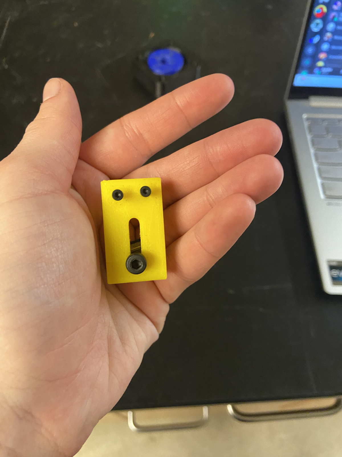
Fig. 7 – Old Limit Switch Attachment
The redesign of the limit switch attachment addressed this in two ways. Firstly, the bottom bolt hole was changed so that it did not have room to slide around. Secondly, the design of the attachment was an L bracket to provide extra resistance to the bracket moving downward.
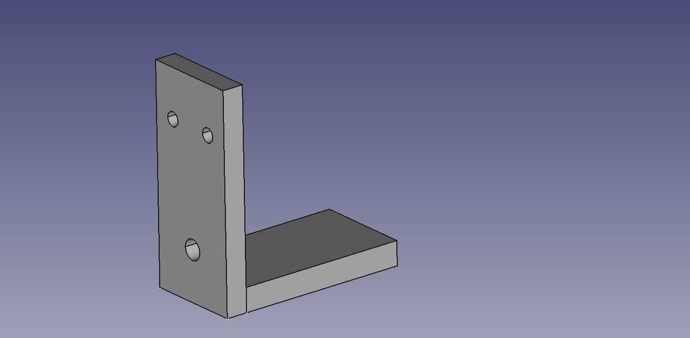
Fig. 8 – Final Limit Switch Attachment design
Despite many attempts at making dimensional changes, the final design printed was too tall. This meant that it was hitting the lid of Lasersaur. Rather than continuous reprints, the final part was filed down so that the limit switch could be pressed.
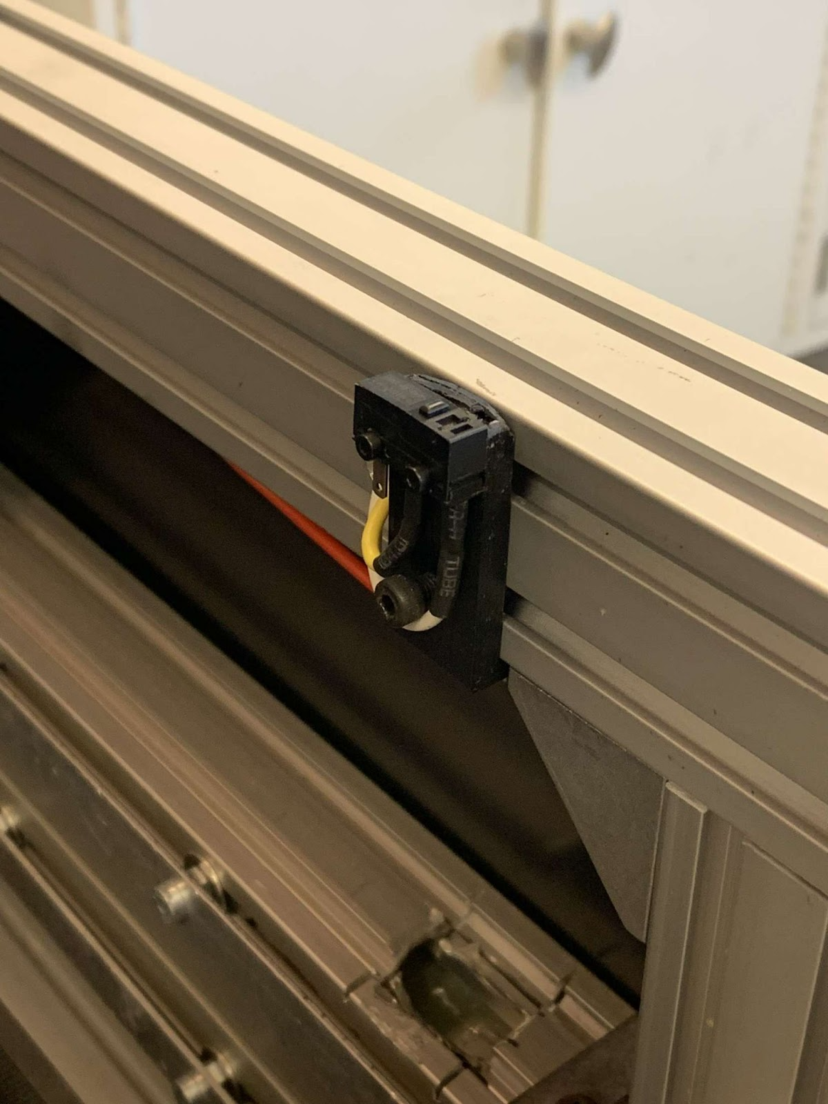
Fig. 9- Limit Switch Attachment
Making the Movement Reliable
The seventh goal on the list is to make sure the machine is secure and make sure nothing was moving that was not supposed to. While moving the support beams that moved the laser, there were a couple of issues that became evident as they made the support beams fall off the rails of the Lasersaur. The first issue was that on the left side of the support beam there are little bearings that move the beam along the rails. One of these bearing was off center of the rail of lasersaur and caused the beam to slip and fall off the rail of Lasersaur.
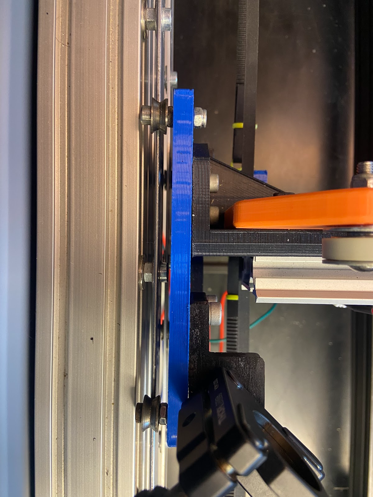
Fig. 10 – Bearings on rail
To try to fix the bearing from falling off, the first thing that was done was to put washers on the bearing to push the bearing out to put it in the middle of the rail.
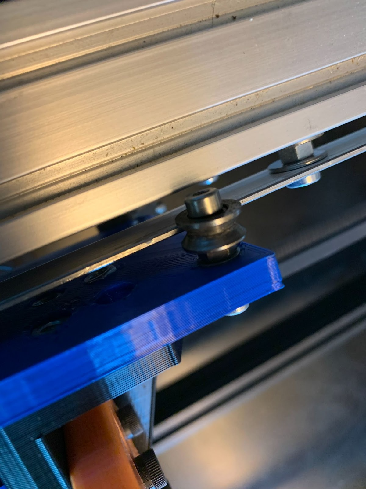
Fig. 11 – Bearings on rail with washer
This somewhat improved the movement but sometimes the bearing still came off of the rail occasionally. So the next thing that was done was to replace the bearing to see if it worked better. This change made the movement improve significantly and the support beams were no longer falling off the rails as often, however there were still problems with the linear bearing that would misalign the laser.
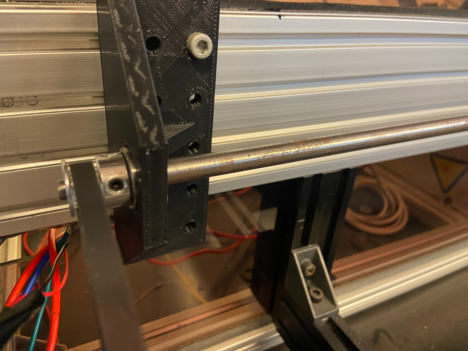
Fig. 12 – Linear bearing
The fastening screw was loose and would allow the bearing to slide out of the mount for it. This would cause catastrophic failure in which the left side of the machine would not move and cause the entire assembly to fall off of the rails. Replacing the bearing proved to be an easy fix, but should be watched in the future to ensure that major problems do not occur while firing.
Changing the Ventilation
The fifth goal on the list is to make sure there is proper ventilation for Lasersaur. Prior to the semester there was a ventilation system in place. There was a tube that led out to Lasersaur and went to a fan which also led to an air duct.
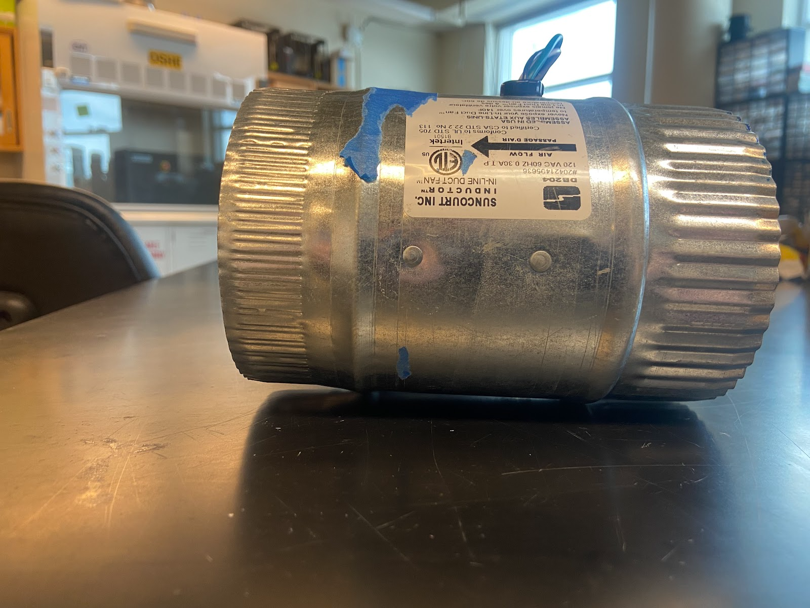
Fig. 13 – Old Exhaust Fan
The design of this system worked fine, however the amount of air flow that coming out of the fan was not enough to remove particles from the Lasersaur. The old fan had an airflow of 65-80 Cubic Feet per Minute (CFM) [4]. Which was not the recommended airflow for Lasersaur. Lasersaur needs to have an air flow of 588-882 CFM [5]. In which this was a problem and the fan needed to be replaced. The new fan has an airflow of 735 CFM which fits the recommended specifications for the Lasersaur. Once the new fan came in the new fan needed to be assembled to work with the ventilation system.
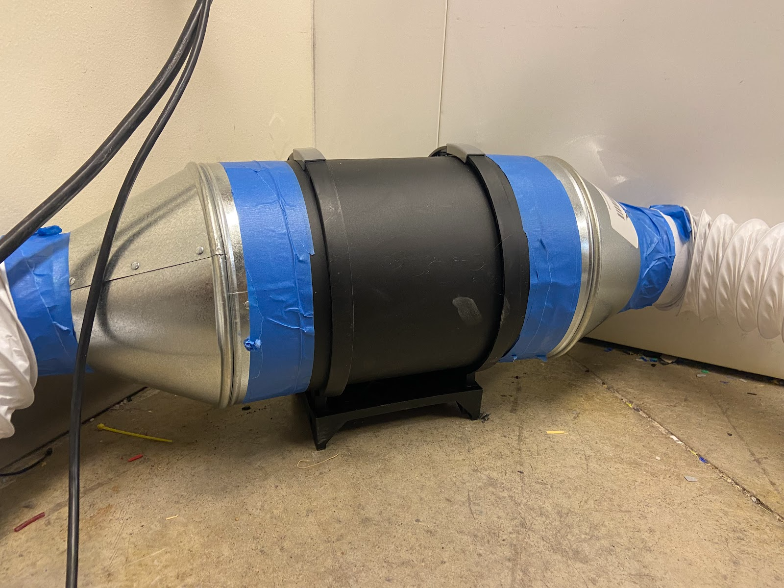
Fig. 14 – New Exhaust Fan
What’s Left?
The next semester of work on the Lasersaur should focus on aligning the laser, testing settings with test cuts, and improving the code. Most of the safety work has been completed at this point, however a full check using OSHA standards should also be completed to ensure there are no unnecessary hazards.
While work has been done to attempt to align the laser, this was not actually completed. In the lab there is a laser diode set in a 3D-printed mount that can be attached to the CO2 laser, as seen in Fig. 16. The current attempts have used this diode to simulate the path the real laser will take. Using that path, the mirrors were adjusted using their controls to make the laser hit the center of each mirror at every point in the machine [4]. The problem with this process is that there is some tilt to the mirror that is causing vertical drift between the first and second mirror. This problem needs to be fixed before the laser can be used.
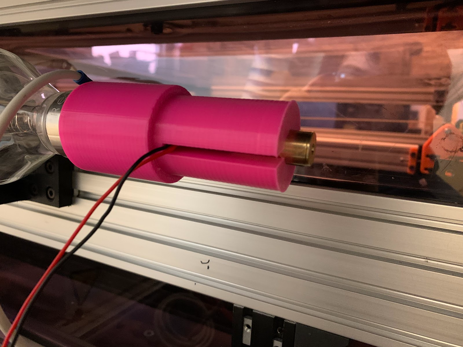
Fig. 15 – Laser diode mount attached to the CO2 Laser
The current ideas for fixing the drift are either adding shims or redesigning the mounts to tilt the mirrors. Tilting the body of the first mirror has seemed to reduce vertical drift as it allows the laser to bounce from the mirror from an angle that tends more downward than without a tilt. The problem is that the exact tilt needed is not known, and too much tilt will make the laser inaccurate. Shimming will provide quick adjustments, however may not be a full, accurate solution. A redesign may work better, but may also move the mirror out of the ideal path of the laser.
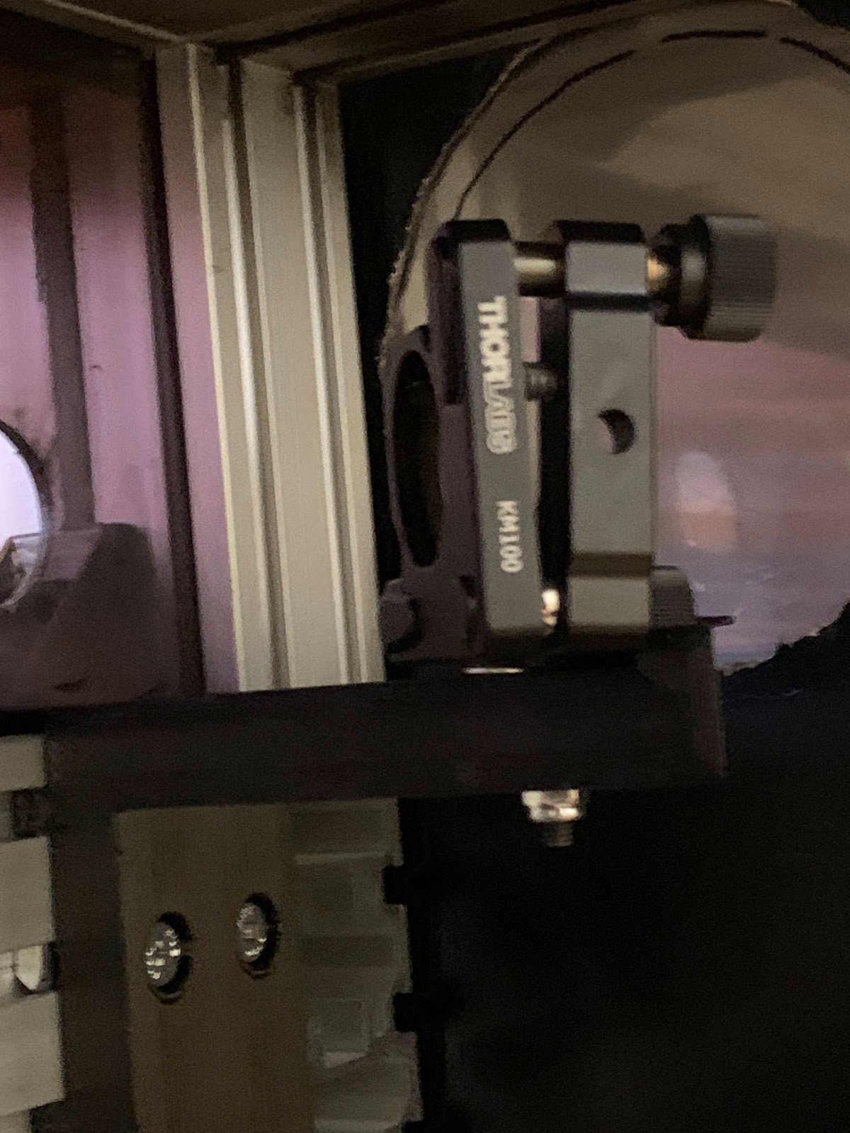
Fig. 16 – First mirror with shim being used to tilt it
Once the laser is aligned and usable, the settings will need to be adjusted to ensure that the proper power is being used for each material. Different materials will need different laser strengths and exposure times to cut through it. The settings for these materials can be adjusted in LaserGRBL, but need to be checked. The code also needs modifications to ensure that any movements made will respect the hard limits of the machine. Currently the code will make an attempt to reach any X or Y coordinates that were entered, but the machine can only move in the area of X0 Y0 to X1200 Y800. Moving past this can cause the motors to run the bracket into the walls of the machine without trying to stop, leading to misalignment. Besides these problems, minor repairs are needed for damages from test firing. Recent firing caused the damage in Fig. 17 on the gear mount.
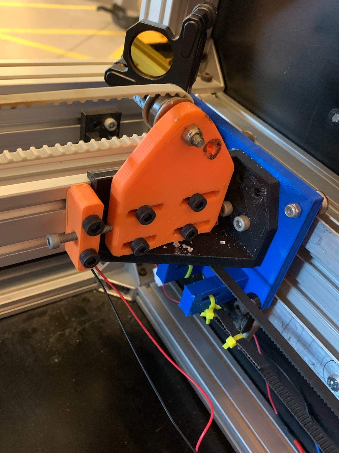
Fig. 17 – Damage to gear mount
Budget
| Part | Total Price | Date |
| Laser Diode | $18.25 | 2/13/23 |
| Door Plating | $127.37 | 3/16/23 |
| Plywood Sheets | $49.08 | 3/16/23 |
| Exhaust Fan | $99.99 | 3/29/23 |
| Duct Converter | $44.14 | 3/29/23 |
| Aviation Connector Plugs (Cooler) | $13.99 | 3/29/23 |
| Total | $352.82 |
Table 1 – Budget spending for the semester
Works Cited
[1] “Checking If the Laser Tube Has Gas Leaking Problem,” SPT Laser. [Online]. Available:
https://www.sptlaser.net/solution/77#. [Accessed: 25-Jan-2023].
[2] “Reci Power Supplyfor 100 -120W W4CO2 Laser Tube.” Reci Laser.
[3] “CW-3000 Industrial Chiller User Manual.”
[4] “Inductor® 4,” Suncourt Inc. [Online]. Available:
https://suncourt.com/products/inductor-corded-in-line-duct-fan-db204c. [Accessed:
22-Apr-2023].
[5] Nortd, “Lasersaur — open source laser cutter,” GitHub. [Online]. Available:
https://github.com/nortd/lasersaur. [Accessed: 22-Apr-2023].