
Written by Madelyn Brown, Joshua Parkinson, and Ben Grumann
Spring 2023 Update
Our Project-
We took upon the task of bringing the Dexter Robot Arm, that had previously been collecting dust in the back of the lab, back to life. Utilizing the work from the previous semester, we planned to make a few ‘Quality of Life; changes to Dexter’s operations. These changes included fixing the loose joints and optical encoders, designing a cover to hide Dexter’s internals, as well as completing previous semester tasks such as palletizing, active user input, and operating the claw. Details regarding these goals are outlined in the Project Spec Document in Appendix Figure 1.
Our Goals & Goal Status-
In our Project Spec document, we proposed that three of our goals would be completed by the middle of the semester. These goals included our palletizing, active user input, and optical encoder repair. To complete our palletizing and user input goals, Dexter had to utilize its end effector similar to a forklift, moving and re-stacking 3D printed pallets from one location to another. The amount of pallets to be moved was determined by the user, using an integrated slider. The fork and pallets were designed in Blender, and files for both are included in the shared drive as well as the Dexter Robotic Arm Repository. A video of the palletizing task was also taken and included in our mid-semester presentation, as well as uploaded as a demonstration on our OSHE social media pages. As for our optical encoder repair, we re-printed the discs used in the encoders and re-attached the sensors to their proper positions. The previous discs were brittle and mostly shattered, especially around the end effector. To demonstrate the completion of this goal, we’ve taken pictures of the repaired optical encoders and included them in Appendix Figure 2.
Our other goals were joint repair, case design, and end effector repair. Loose joints on the robot were most prevalent around the end effector as well as the center of the robot, causing gears to slip off of the motors and be generally loose. It’s speculated that they were worn down over semesters of use, and the current solution was to wrap small amounts of teflon tape around the motor shaft, creating more friction between the gears. This worked well, allowing them to stay on properly. The case design for Dexter was more for looks, if the robot is to be used in future demonstrations. It was designed in Blender as well, and is meant to hook onto the back of the robot without hindering its range. The case has gone through two iterations thus far, and due to printing issues in the lab, could not be tweaked as much as we originally would have liked. The nature of Blender also requires the case to be resized within the printing software before it’s printed. An image of the designed case sporting the OSHE logo is included in Appendix Figure 3. Finally, we had to sort out the problem with our end effector. Despite our efforts, we could not figure out how to connect the original claw to Dexter’s interface, and turned to Arduino to use as a secondary means of controlling the claw. Using previously bought servos and an end effector originally used for Dexter, we created test codes that can open and close the claw as desired. These codes are saved within the shared drive, as well as our repository.
Another small goal of ours was to keep up with the organization and documentation system we had implemented last semester. This is evident through the organization of our repository, and the content within our shared drive. All of the information within the team’s drive is available through the repository to assist future teams who will work on Dexter.
Replication Procedure-
To encourage future work on Dexter, a Standard Operating Procedure was developed. This allows future teams to replicate our work using both the SOP, this document, and our repository to gather all necessary information. Included below as well are links used through both semesters working on Dexter that were helpful for implementation.
Dexter Standard Operating Procedure: [SOP] [Included in the Appendix]
Basic Information/Links
This robot is an older model of a Dexter 5 axis arm by Haddington Dynamics. The arm is mostly 3D printed and entirely open source. To program it, it uses Dexter Development Environment [DDE] which can be downloaded from the link below:
[Dexter Development Environment]
There are a couple other links that we found useful when first working on the arm.
Hackaday page with assembly videos: [Dexter | Hackaday.io]
Official Chemtron website with specs: [Dexter: An Award Winning Robotic Arm]
OnShape page with a full model of the arm (newer model): [CAD Arm]
Dexter github page: [Github]
End Effector Wiring Documentation: [End Effector Page]
Thingiverse 3D Printable Parts: [Dexter Arm Files]
OSF Repository-
OSF Repository Link: https://osf.io/x8z5j/ [Includes original files & sample code]
Appendix-
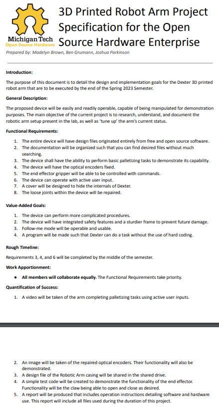
Figure 1: Project Spec for Dexter
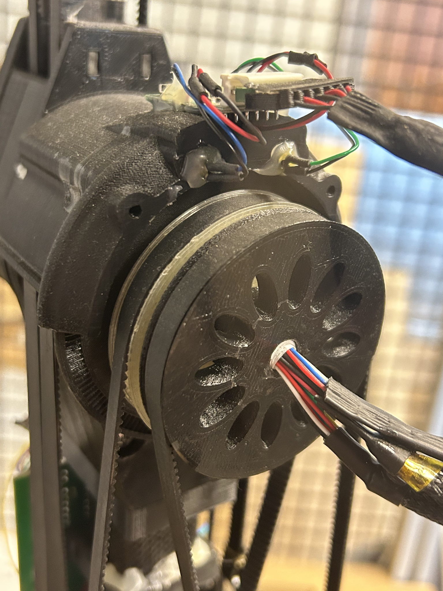
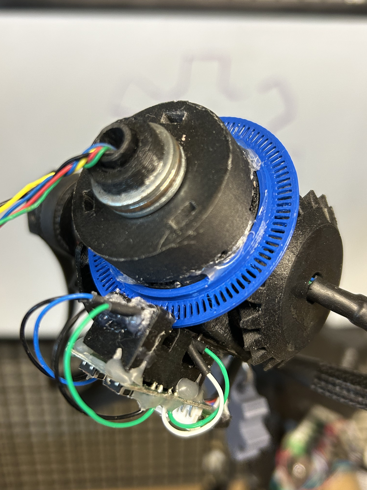
Figure 2: Repaired Optical Encoders
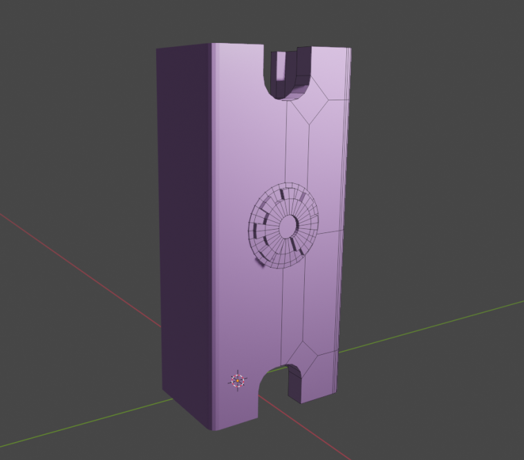
Figure 3: Completed Case Design
Dexter Robotic Arm Standard Operating Procedure
Last updated 4/07/2023
Purpose:
‘Dexter’ is the name of the robot arm in the corner of the OSHE lab, and it can be used for a variety of projects if you have the bravery to take on a challenge. This SOP can be used to get an individual started with using Dexter, including startup, connection, and very basic movement.
Related Topics:
Dexter Development Environment (DDE) is a custom program that is used to connect to Dexter. It can use pseudo-Java code or ROS, and this document will assume Java is the default. Install DDE on your device before continuing.
Context:
Dexter is a robot that’s currently in progress. There are a lot of issues, such as consistent homing, calibrating, loose joints, and other mechanical issues. This SOP can be updated in the future to accommodate further repairs or modifications.
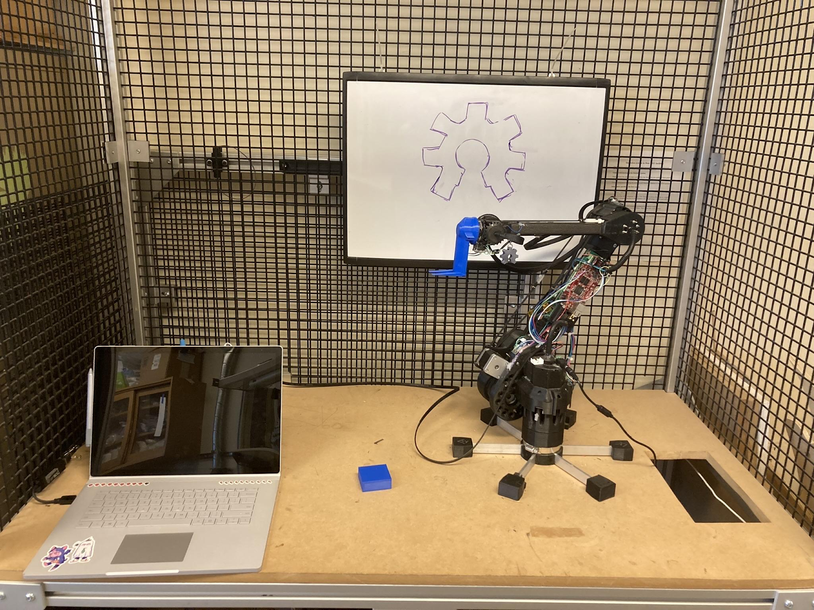
Fig. 1: Dexter Robot Setup In Lab
How to Start Up:
- To boot up the robot, make sure that it’s plugged into the front power supply and the E-Stop button is pressed (The robot should be off initially). It should be oriented with the circuit board facing towards the front, and all other joints pointed straight up.
- Small white markers on each joint indicate its intended ‘home’ position. Manually move the robot’s joints to where the markers align- with no power, this should take minimal effort.
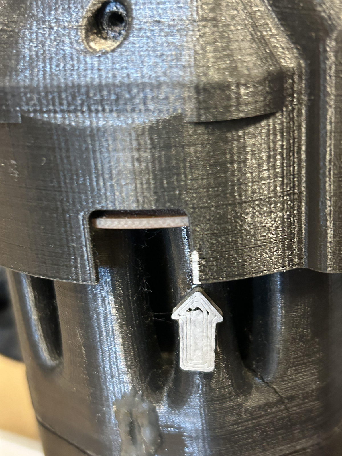
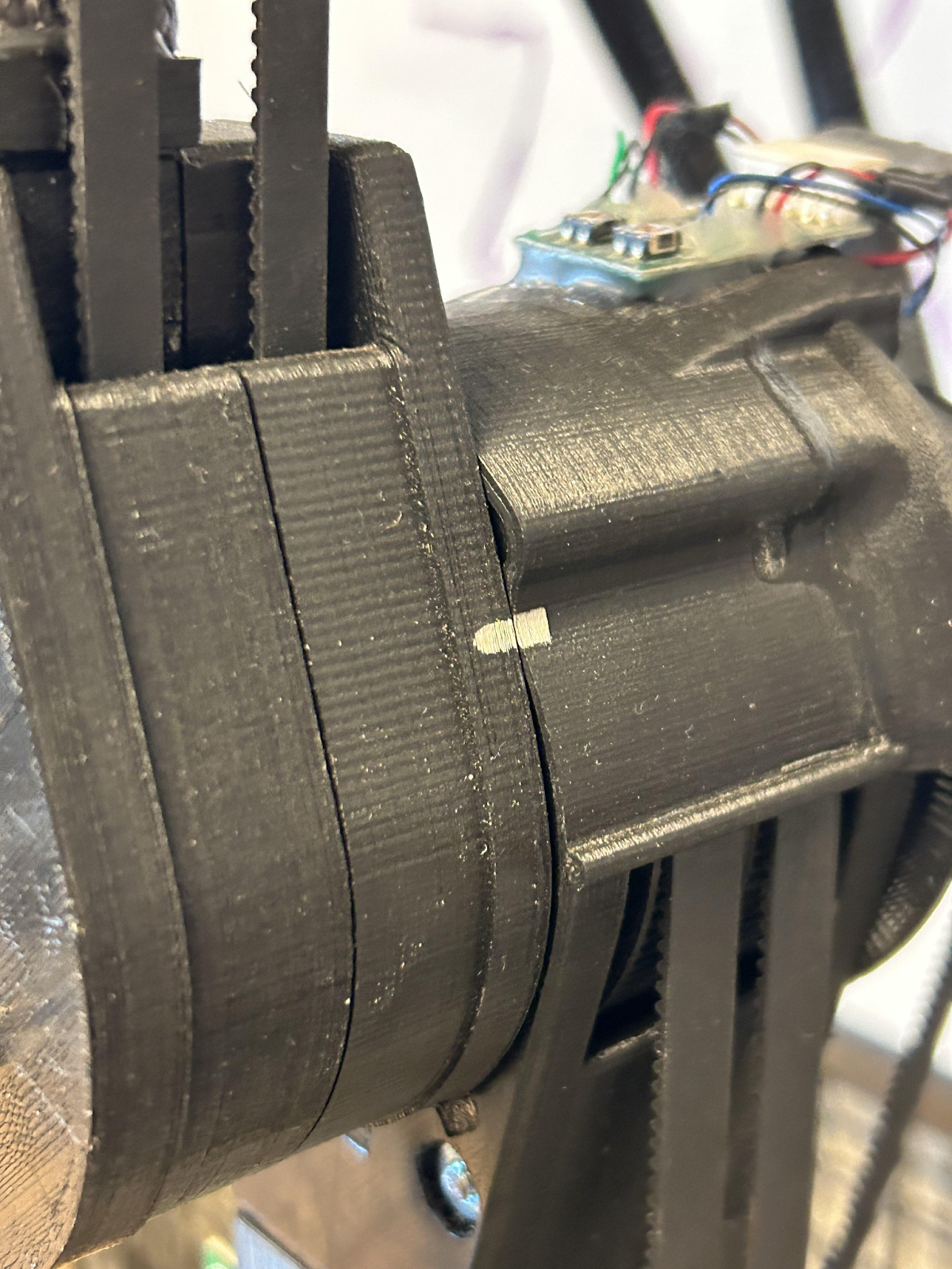
Fig. 2 & 3: Alignment Markers on Dexter
- Check that all of the belts are connected to their respective motors and gears, and that everything required for operation is connected to the robot (panels over the bearings, screws in the board, anything that was previously taken off for repair, etc.).
- Undo the E-Stop button to give the robot power. There should be a few lights on the board that turn on when the robot is plugged in [Green, Blue, and currently a flickering Red, as well as green lights near the joint cables], and the fan at the front of the circuit board will start up.
- After ~30 seconds, the robot will do a small ‘dance’ to initialize, and then it should be good to plug in to your computer and program. Wait until the robot has initialized to plug it in, or else it could confuse the programming and cause later issues.
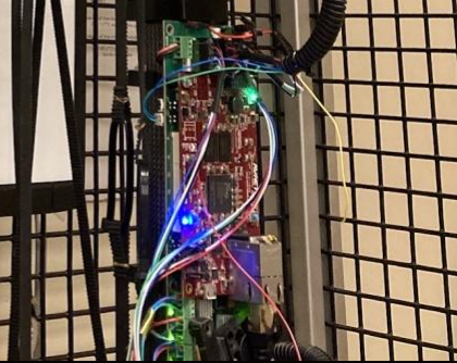
Fig. 4: Lights on Circuit Board
How to Connect to Dexter:
- To connect to the robot, Dexter uses an ethernet cable. The cable plugs directly into the board, then directly into the machine that can run Dexter Development Environment, or DDE. Dexter can also be connected to a computer via a micro usb cable, though that connection is more convoluted [requires outside programs], so it’s easiest to use the ethernet cable and a USB adapter if your laptop doesn’t have a port.
- Upon bootup, DDE should have some sample code already that initializes ‘dexter0’, or the default robot. The IP should be set to 192.168.1.142 . To run this code, and all jobs in general, highlight the lines you wish to run, then hit the ‘Eval&Start’ button near the bottom left. This should initialize the robot.
- In order for your ethernet port to recognize Dexter is connected to it, you have to manually set the IP. Go to Settings > Network & Internet > Ethernet, or just press Start and type in Ethernet. Set the IP Assignment to Manual, and edit the IPv4 settings to:
IPv4 Address: 192.168.1.140 (Cannot be the same as the Dexter IP)
IPv4 Mask: 255.255.255.0
- Re-Initialize Dexter in the DDE terminal for good measure, then run a test job to make sure the robot is connected properly. Test jobs can be found under the ‘Jobs’ menu near the top of the workspace. We usually run the ‘NEUTRAL_ANGLES’ instruction under ‘Run Instruction’ to make sure everything is operable.
How to use Dexter Development Environment:
DDE is a little difficult to understand, and even through our current research, we still don’t know its full capabilities. The interface itself can be a bit overwhelming, so we’ll run through the quick basics of running code. All of this information and more is available within the program through the help center, which is located on the top right side of the screen.
- Initializing Dexter- In depth
In order for DDE to run code, a robot must be defined within the software. Luckily, this code is given to you when you boot up the program, but just in case, here’s what you should be seeing:

The Dexter IP address is the IP of the robot, and will be fixed. Unless you plan on changing the robot’s IP, this doesn’t need to be altered. ‘dexter0’ is the name the robot will be given, and can be changed if needed.
To run these lines, they have to be selected. You can run each line individually by pressing ‘ALT’ and clicking the code, or click and drag to select all of them. Then, near the bottom of the screen, hit the ‘Eval&Start’ button. This will be used to run jobs in the future.
- Jobs
When you want to run a command in DDE, it needs to be defined as a ‘job’. There are plenty of sample codes that demonstrate this syntax, and can be inserted into the file under ‘Jobs’ > ‘Insert Instruction’ menu at the top of the screen. Under ‘Jobs’ > ‘Run Instruction’ there are commands that will run immediately after clicking them. The ones we used the most were ‘HOME_ANGLES’ and ‘NEUTRAL_ANGLES’. Home brings the robot to the position it was initialized at, and Neutral brings all joints (except J1) to a 45 degree angle.
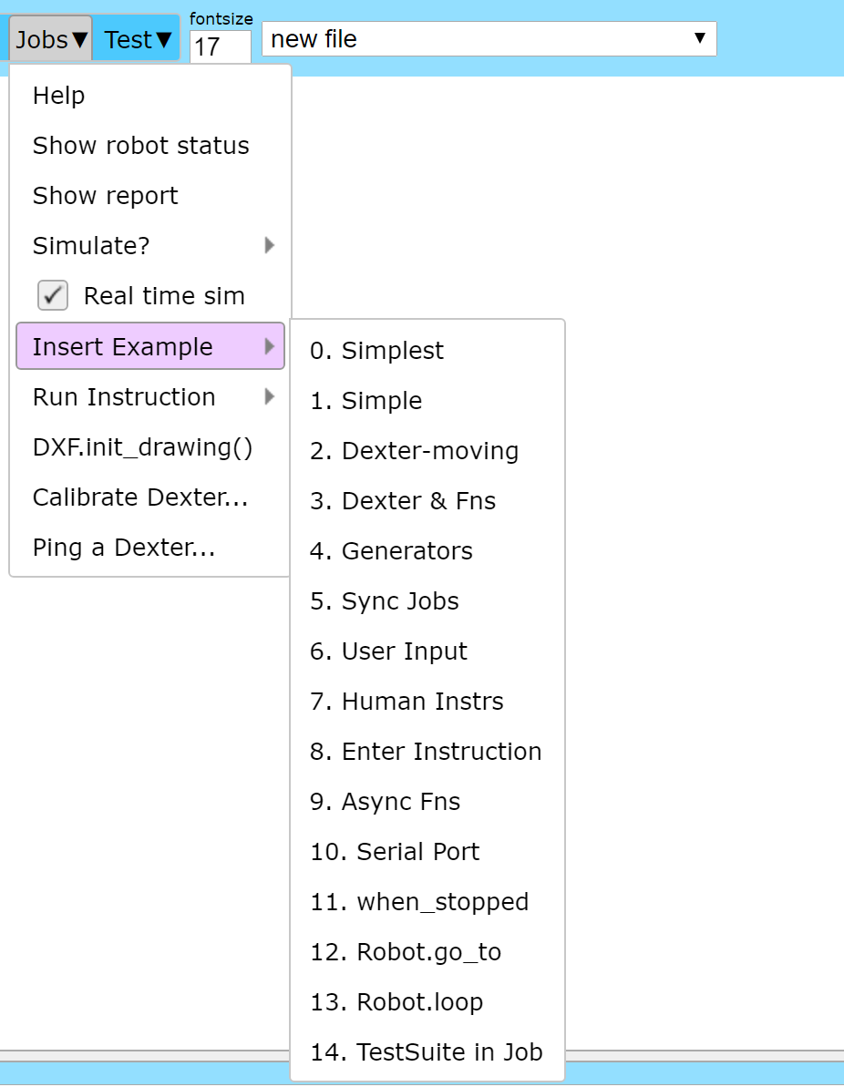
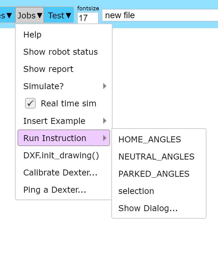
Fig. 5 & 6: Examples of DDE ‘Jobs’ Menu
To move the robot, you can use the commands ‘Dexter.move_all_joints([])’ and ‘Dexter.move_to([])’. The first command takes inputs as angles for all joints, while the second takes a coordinate in space, though the move_to command is a bit finicky and very precise. While DDE gives you a supposed range and limit of motion, sometimes the robot has trouble finding its way there. We found the move_all_joints command to be simplest to work with, though tedious.
More syntax examples are available through sample code or searching the Help Center.
Link to some of the code we’ve used previously: [Sample Codes]
- Simulation Mode
In the bottom right of the DDE interface, there is a small box that is used for robot simulations. This is helpful when testing code to make sure the robot doesn’t damage itself when running. To turn simulation mode on and off, go to ‘Jobs’ > ‘Simulate?’ > and select which option you prefer. The robot will not move if simulation is set to true, and will instead show its process on screen.
- Help Center
The Help Center within DDE has been very helpful when providing us with syntax, ideas, and examples to follow when we work on our own code. Many other questions can be answered there, and if we haven’t covered the specifics of what you’d like to do, it’s likely you’ll find the information there.
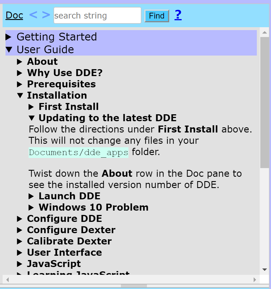
Fig. 7: DDE Help Center Window
Search for commands with the top search bar, or any other keyword, and where in the documentation your keyword is located will light up orange.
- Other Help
OSF Repository with previous group work. [https://osf.io/x8z5j/]