
Open Source Open Platform Quadcopter
Spring 2022-Fall 2022
Timothy Sucarski – Mechanical Engineering Technologies
Nathan Fisher – Electrical Engineering
Dr. Shane Oberloier – Enterprise Advisor
Michigan Technological University
Open Source Hardware Enterprise
Houghton, MI 49931
Table of Contents
I. Previous Year Summary
II. Acknowledgements
III. Introduction
IV. Objectives and Constraints
A. Objectives
B. Constraints
V. Drone Rework
A. Frame
B. Vision
C. Final Wiring Diagram
VI. Final Comments on Drone Build
VII. Arduino Sensor Pack
A. Setup
B. Sensors
1. Openlog
2. SGP30
3. Sensirion
4. Lidar
VIII. Electrical/Mechanical Hardware Assembly Procedure
IX. Final Comments on Microcontroller Integration
Appendix A. Links
I. Previous Year Summary
https://openhardware.eit.mtu.edu/index.php/2022/12/16/open-source-hardware-enterprise/
Originally, the Open Source Cinematography Quadcopter Project was worked on by Joaquin Ganoza and Christopher Hettinger. The original intent of their project was to design and build a quadcopter using 3D printed components and consumer electronics that was able to interface with sensors mounted on an arduino microcontroller and complete autonomous missions to collect data using those sensors. This project was named Open Source Open Platform Quadcopter.
This project was previously focused on FEA for the components to design a frame that would be able to hold up better in a crash than other 3D printed drones. This frame was much bulkier in the areas where breakage was most likely to occur. Additional considerations were made as to what material was used to 3D print the frame as well as what settings and orientations to use while printing in order to retain the expected strength characteristics.
II. Acknowledgements
The Open Source Open Platform Quadcopter team would like to thank those involved within the Open Source Hardware Enterprise for the opportunity to continue this project and the collaborative efforts that were brought forth during this redesign. The team would also like to thank Dr. Shane Oberloier for his guidance in this project and for creating an enterprise environment conducive to learning and collaborating.
III. Introduction
When our team was first tasked with turning this project into a more utilitarian sensor quadcopter from its previous intention as a cinematography quadcopter, we decided that the frame once again needed to be redesigned. This choice was not made lightly, however it was concluded that one of the reasons that this drone was not able to fly up to this point was because of the extra weight that would only protect it from a fall should the drone be able to make it into the air in the first place. The new frame would be much lighter, but still structurally sound enough to be able to withstand the forces on the frame from the various parts of the drone. An effort was made to salvage all electronics from previous iterations as to not add undue costs to the project. As such, the decision was also made to remove the microcontroller and sensors from the drone in a way that the same sensor package and code that was used in our project would be able to be used with any other drone so long as it has a standard camera mounting knuckle system. This adds to the spirit of open source as many consumer drones already have this mounting system and a new drone is not required should anyone only require the use of the sensor package. This then separated the project into creating a drone and creating a sensor package.
IV. Objectives and Constraints
A. Objectives
The overall goal of this project is to create a drone capable of flight as well as create a separate sensor package that can be integrated onto this drone and many others that is capable of collecting and storing data. All of this was to be done utilizing open source manufacturing practices as well as consumer-grade components. Here are the goals set for this project:
- Open-Source Part Files for Modification
- While all of the parts were designed in Onshape, a free CAD software, the part files will be made available in the PARASOLID format, which can be opened and edited by many other CAD softwares.
- Open-Source controller hardware
- MATEKSYS F405-miniTE flight controller running iNAV.
- Allows the community to use different styles of iNAV supported flight controllers for functionality.
- Arduino Nano for sensor control/data acquisition and logging.
- 3D Printed Components
- Allows for low cost manufacturing of new and existing components
- Perform basic quadcopter flight maneuvers
- Ability to be controlled from a handheld transmitter.
- Take off and land safely.
- Precise and accurate controls.
- Sensor package
- Capable of interfacing with sensors and logging data
B. Constraints
Here are the limitations placed to keep the design accessible to any open source enthusiast:
- Open-source tools will be used to manufacture the frame of the quadcopter
- 3D printing will be the basis of manufacturing for this project.
- Must be able to withstand forces during flight.
- Any changes from the previous designs must remain under $100.
- Complete the project within a 1 semester time frame.
V. Drone Rework
A. Frame
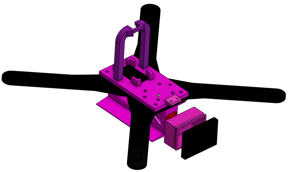
As the drone was not in flying condition when it was received by our team, the first goal was to take it back to the most basic form and work from that to attempt to get it to fly. This meant scrapping the frame that was used by the previous group that worked on the project in favor of something much lighter and easier to work with. To fit that goal, it was decided that it would be best to use flat arms printed out of ABS for the added ductility, while the center of the frame would be printed out of PLA. Figure 1 shows the design in Onshape while Figure 2 shows the printed frame with electronics mounted.
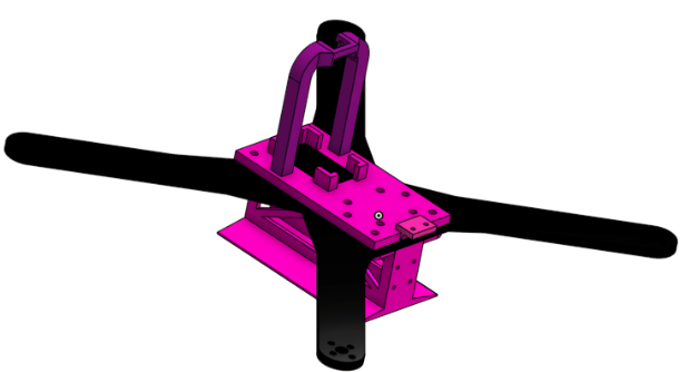
Figure 1: CAD of the new drone frame. The parts in pink are to be printed in PLA while those in black are to be printed out of ABS
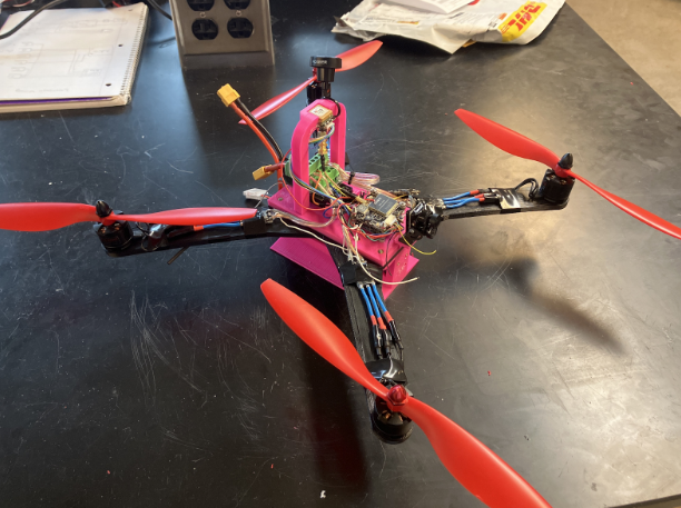
Figure 2: Printed frame with electronics mounted.
This frame redesign uses individual arms so they can be replaced individually if one breaks as well as reducing the size of the 3D printer that would be required should anyone want to replicate this frame. The battery being mounted vertically allows for easy access to the undercarriage as well as additional mounting points for sensors. This also provides a continuous flat base to calibrate the gyroscope off of as opposed to just the screws on the bottom of the frame that would be used otherwise.
With this new design, it is also now possible to mount the motor speed controllers (henceforth referred to as ESCs) on the arms; freeing up a lot of space in the middle of the frame for the flight controller and vision system (more on that later).
B. Vision
The last iteration of the drone featured a Runcam hybrid camera with an integrated video logger. This was able to run using a spare UART on the flight controller and allowed remote starting and stopping of the video. Unfortunately, during the electronic overhaul, this camera logger broke as one of the pads completely sheared off. This camera system would have worked fine with the rest of the vision changes, but cheaper options are available, and that is what we ended up using.
While a video system is not strictly necessary for a drone that is focused on sensors and autonomous navigation, it does improve the quality of life of the user considerably. The ability to have metrics on how many satellites as well as any error messages is very useful for troubleshooting. As such, I would recommend a FPV camera as well as a video transmitter (VTX) and video receiver (VRX). This equipment uses analog video transmission, which works with nearly any analog VRX. Any VTX and Camera work, but I used a Caddx Ratel 2 for the camera and a Wolfwhoop Q3-S video transmitter. For the VRX, I used my Skyzone 04X goggles, but there are also video receivers that can be found with A / V out so that they can be plugged into a monitor that takes A / V input. With this vision setup, errors and data are able to be viewed in real time and are editable via the OSD settings in iNAV.
C. Final Wiring Diagram
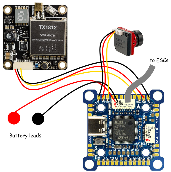
Figure 3: Flight Controller and video transmitter wiring diagram. Only part of the wiring that is not pictured is the speed controllers each being put in parallel with the battery and connected to the PWM pins pictured above in gray.
VI. Final Comments on Drone Build
In order to test motor thrust indoors, GPS and magnetometer needed to be disabled. This is not recommended as it is best practice to never arm anything with propellers on indoors; especially something of this size. Those in the future with this project that are looking to add that functionality back would need to enable the gps on UART 5, as well as add the following options into the sensors and buses settings: ICM42605 Accelerometer, QMC5883 Magnetometer, and SPL06 Barometer.
There is a reason that many drones do not use 3d printed frames. Among those are that it is heavier than carbon fiber while also not providing the same amount of stability that is expected from the flight controller. There are open source drone frames as well as services such as cncmadness that focus on cutting carbon fiber for use in drone frames. That weight problem, along with the inherited underpowered motors, causes the drone in its current state to be incapable of flight. For those looking to replicate this project, I would suggest a prebuilt drone, or components that are intended for use in a system like the one that this project requires. Additionally, the RC control link ELRS is open source, and much work has been put in by the community to make it one of the best and most user-friendly control links on the market. Most modern flight controllers are able to be flashed to iNAV, and modern 4 in 1 speed controllers are able to simplify the wiring process to be much more manageable than the separate speed controllers and requisite battery breakout board. Modern flight controllers and speed controllers are both able to simplify the build process as well as support more powerful motors, which would be required to be able to spin a 10 inch propeller with enough force to be able to adequately lift a drone of this mass. The sensor logger has been designed in a way to fit using a standard knuckle system that has been included into many drones that are currently on the market, and is able to be adapted onto. The model for the casing is printed solid so that holes can be drilled for wires in and out of the microcontroller. If there is a need for making this more resistant to water without conformal coating the microcontroller, then it is possible to plug these holes with silicone or hot glue. Depending on the intended use case, a multirotor may not be the ideal platform for the sensors required, and a more conventional plane design may serve some users better. This variability is the reason that we designed the sensor system to be removable and attachable to any platform that fits a specific use case.
VII. Arduino Sensor Pack
A. Setup
To upload any code to an Arduino nano, two prerequisites need to be met first. First, the correct drivers need to be installed. This is addressed below. Next, the correct processor needs to be selected. Choose the old bootloader shown in the figure below.
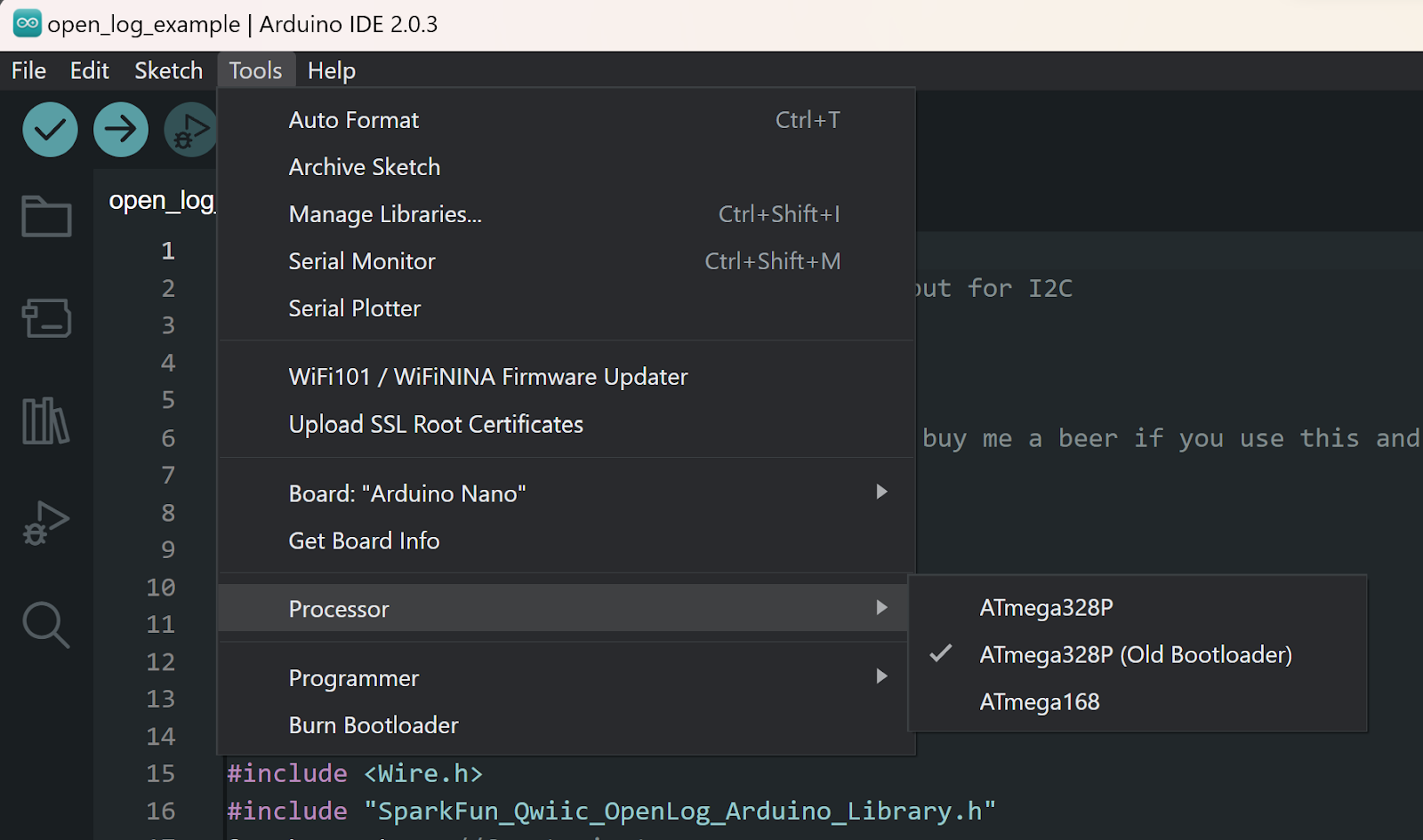
Figure 4: Arduino IDE processor setting for our project’s microcontroller.
To find if the current Arduino is not genuine, refer to the two images below. Notice the different shades of blue and the different reset button styles. The first image is a generic microcontroller, so the drivers in Appendix A would need to be installed. SCA is pin A4 and SCL is pin A5 on the Arduino.
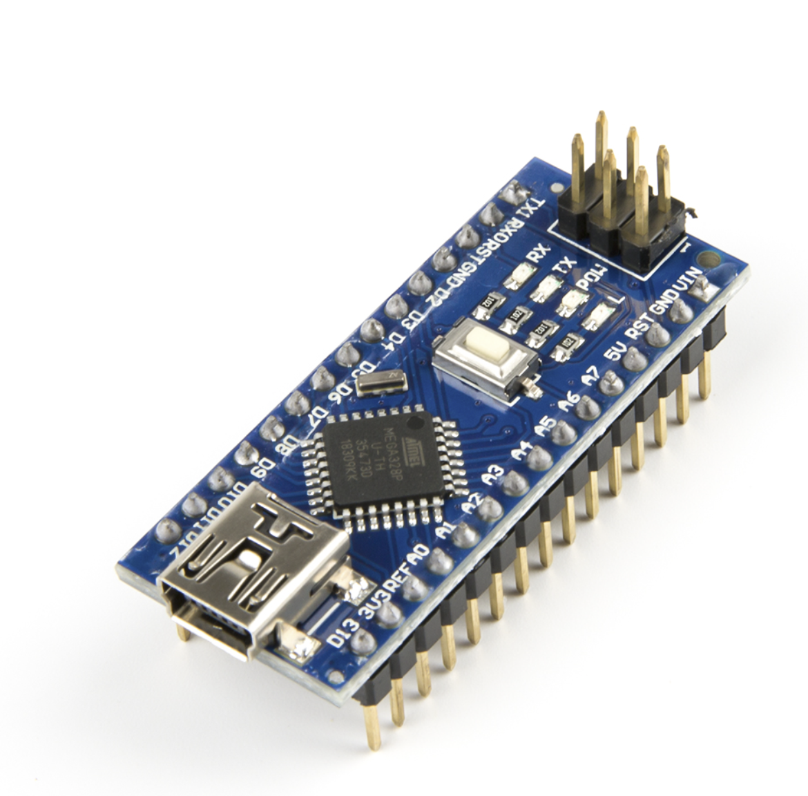
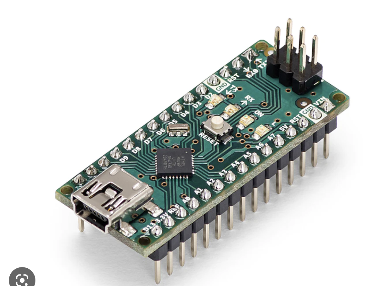
Figure 5: Genuine Arduino (top) and our microcontroller (bottom). This distinction is important to keep in mind so that users have the proper drivers to be able to connect to their unit.
If an uploading error is given after these steps are taken, it is possible that the Arduino is fried.
B. Sensors
1) Openlog
This is the data logger that writes all of the measurements to a micro-SD card.
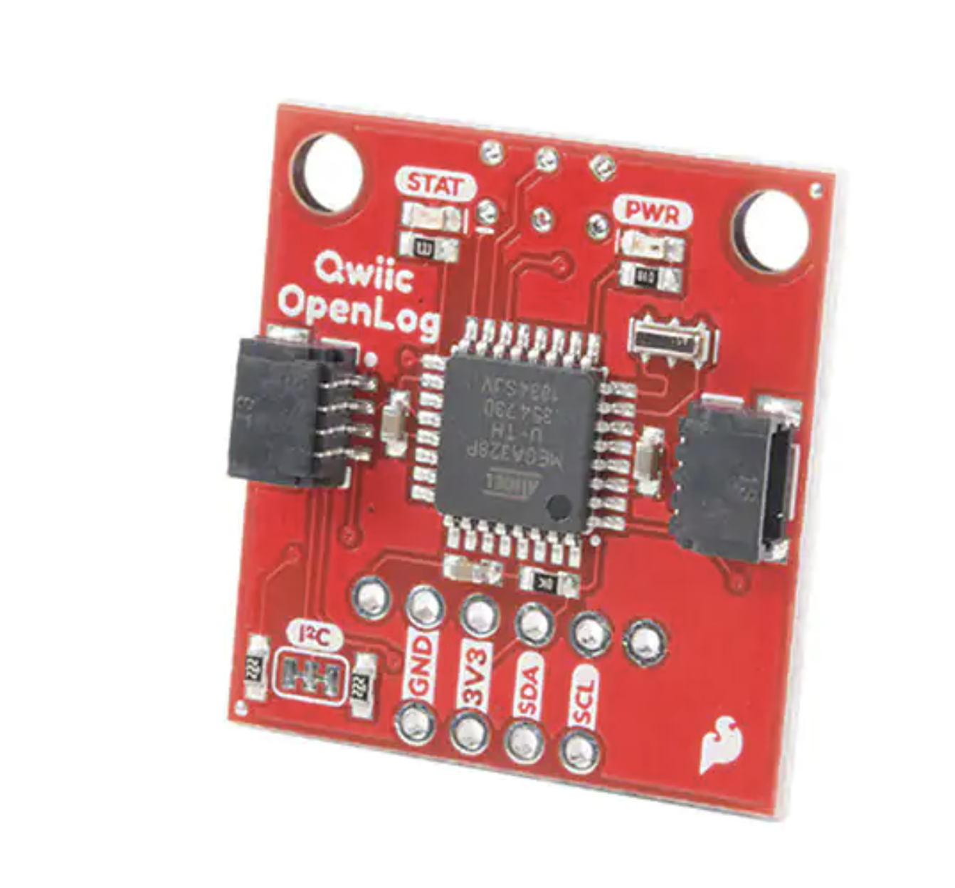
Figure 6: Openlog data logger
Pinout for connectors
| Pin on sensor connector | function |
| top | SCL |
| 2nd to top | SDA |
| 2nd to bottom | 3 V power |
| bottom | gnd |
2) SGP30
This is the air quality sensor. It measures CO2, Total Volatile Organic Compounds (TVOC), and alcohol density.
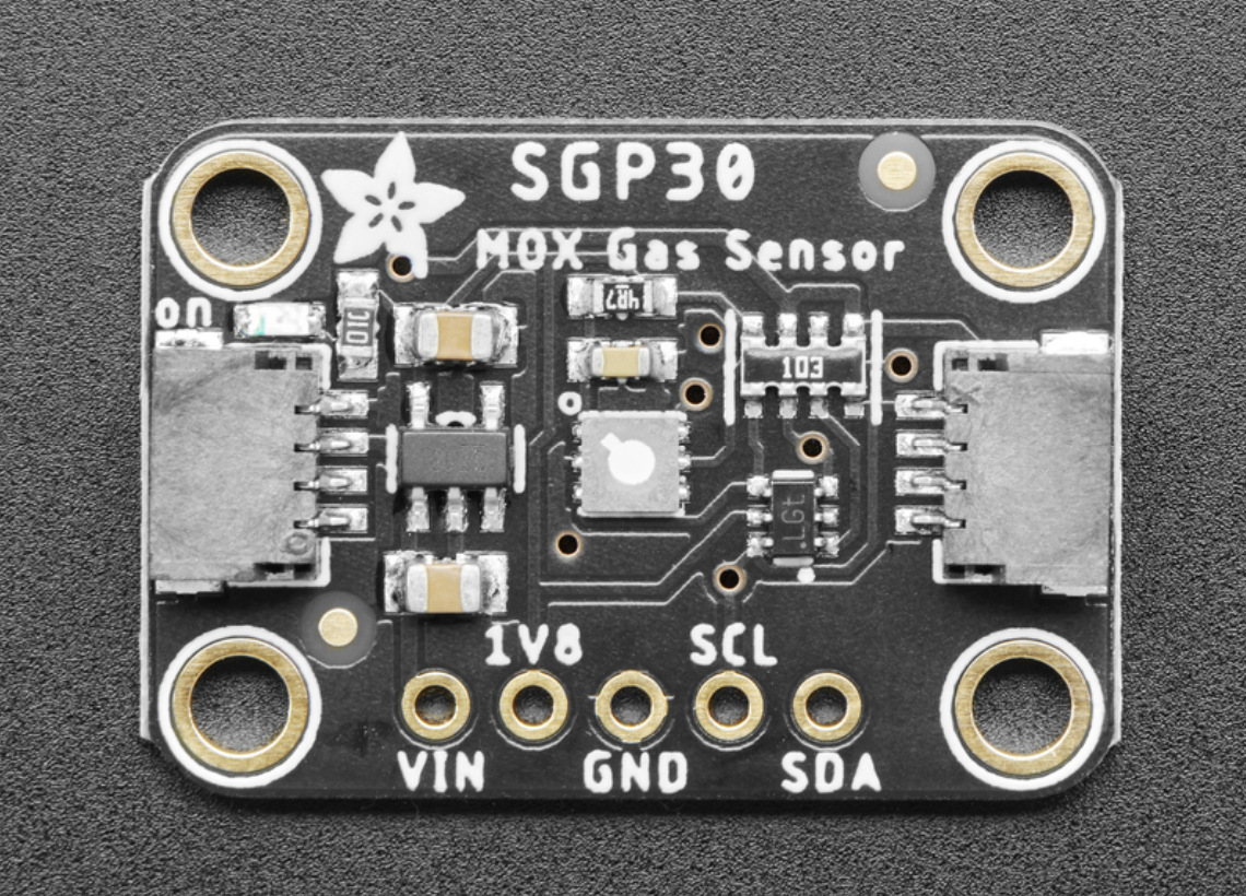
Figure 7: SGP30 air quality sensor.
Pinout for connector
| Pin on sensor connector | function |
| top | SCL |
| 2nd to top | SDA |
| 2nd to bottom | 3 V power |
| bottom | gnd |
3) Sensirion
This is our humidity sensor.
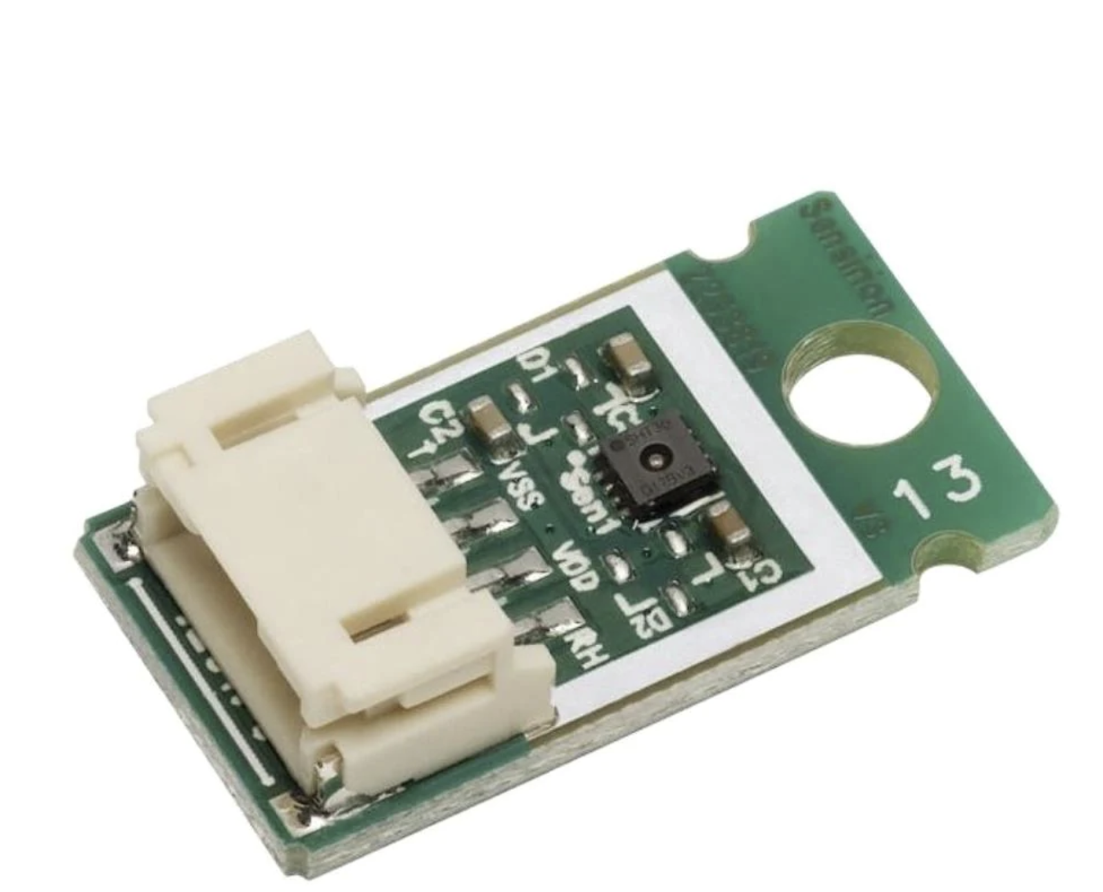
Figure 8: Sensirion humidity sensor.
Pinout for connector
| Pin on sensor connector | function |
| left | SCL |
| 2nd to left | gnd |
| 2nd to right | 3 V power |
| right | SDA |
4) Lidar
This is used to measure distances.
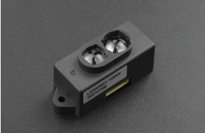
Figure 9: Lidar sensor.
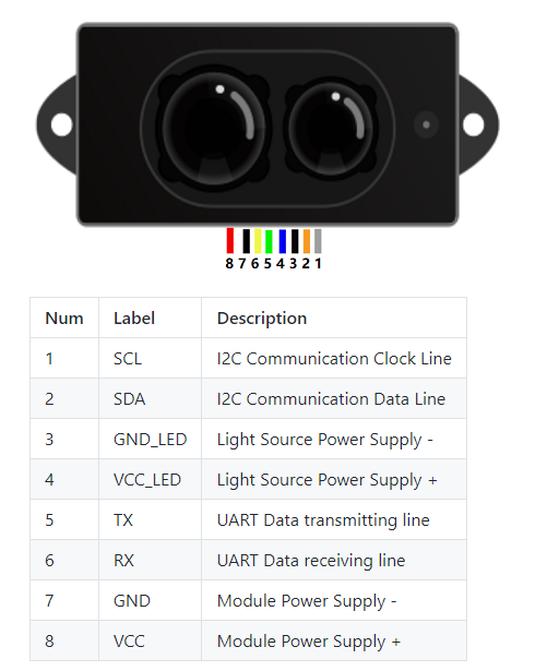
Figure 10: Lidar sensor pinout
VIII: Electrical/Mechanical Hardware Assembly Procedure
The Arduino is embedded into a screw terminal shown below. Sensors have connectors with bare wire on the ends in order to connect to the terminal. Find all pinouts in section VI. Arduino Sensor Pack.
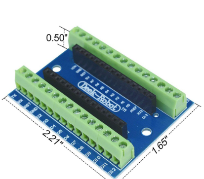
Figure 11: Microcontroller breakout board.
IX. Final Comments on Microcontroller integration
Most of the semester for the Arduino sensor pack team was spent taking inventory and validating the given hardware. They found the datasheets for all of the given sensors to confirm the pinouts. They also found code published online to validate certain sensors such as the SGP30 and openlog. The SGP30 still works, while the openlog does not. In the future for the Arduino sensor pack team, it would be beneficial to solder jumper cables onto the sensors so that they can be breadboarded to the Ardino. That makes the troubleshooting process much faster and may make it easier to diagnose the issue with openlog. After the openlog is figured out, either a custom PCB can be designed to connect the Arduino and the sensors or custom connectors can be made to accomplish this same task.
Appendix A: Links
| Description | Link |
| SPG30 Github | https://github.com/sparkfun/SparkFun_SGP30_Arduino_Library/tree/main/examples |
| Arduino driver installation | https://sparks.gogo.co.nz/ch340.html |
| SPG30 datasheet | https://cdn-learn.adafruit.com/downloads/pdf/adafruit-sgp30-gas-tvoc-eco2-mox-sensor.pdf |
| Openlog datasheet | https://media.digikey.com/pdf/Data%20Sheets/Sparkfun%20PDFs/DEV-15164_Web.pdf |
| Sensirion datasheet | https://www.mouser.com/datasheet/2/682/Sensirion_Humidity_Module_SCC30_DB_Datasheet-1863525.pdf |
| Openlog Github | https://github.com/sparkfun/SparkFun_Qwiic_OpenLog_Arduino_Library |
| Lidar datasheet | https://wiki.dfrobot.com/TOF_IR_Distance_Sensor_0.2_12m_SKU_SEN0413 |