
Background
The objective of our project is to design a 3D printer extrusion system to measure recycled filament diameter and automatically adjust feed rate to maintain consistent volumetric flow rate while printing.
Nearly 20% of extruded filament in fused deposition modeling (FDM) 3D printing becomes waste; the Restruder project will allow the filament to be reused after recycling. Commercial recycling/extruding systems that produce filament with highly precise diameters are costly, so we are developing a system that will ensure optimal printing results every time at the extruder. For context, recycling systems made by members of the maker community are typically only able to achieve a diameter tolerance of about ±0.10mm, while newly manufactured filament today typically has a tolerance of ±0.03mm. Restruder aims to allow improved print quality when using filament with large diameter tolerances. At a high level, the block diagram below shows how the system will likely be designed.

Functional Requirements
- Device can handle filament diameter range from Recylebot (20%)
- The system is able to measure the filament width (20%)
- Maintains desired flow (20%)
- The system includes a controller and stepper motor packaged neatly within a 3D printable enclosure (20%)
- Design the system without changing the firmware of the printer (20%)
Filament Diameter Sensor
The first goal of the semester was to be able to find a better more reliable filament diameter sensor. The previous filament diameter sensor had some issues and was not working as intended. After some research there was an open source low cost inline filament diameter sensor that uses a linear hall effect sensor to detect the amount of distance that a lever is moved based on the diameter of the filament found in the open resources used in design section.
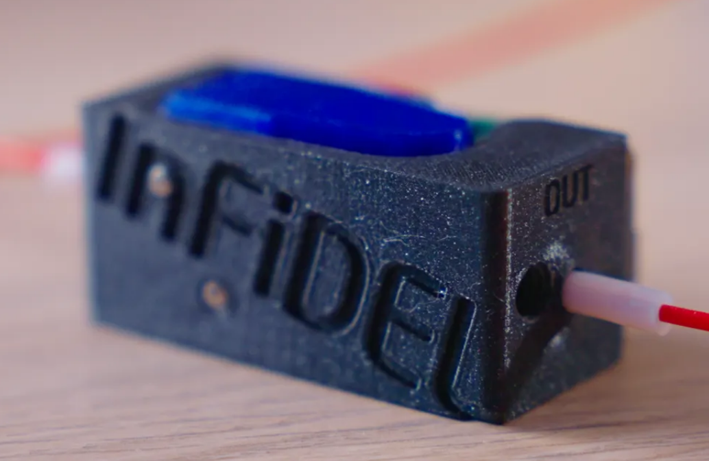
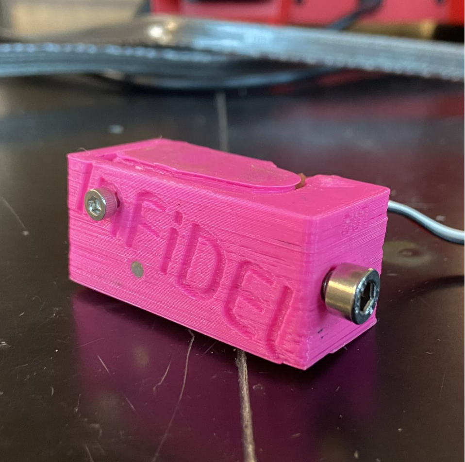
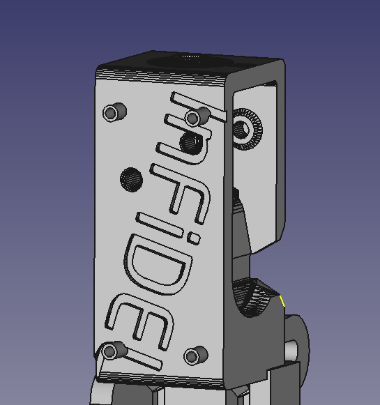
InFiDEL – Inline Filament Diameter Estimator
While first starting to work on making the inline filament diameter estimator there were a bunch of issues when printing the main body of the sensor. First, the sensor was first printed with ABS filament which created a lot of support and made it very difficult to remove and end up snapping one of the important pieces. Also the print ran out of filament at the end of the main body but it was not going to affect the sensor use.
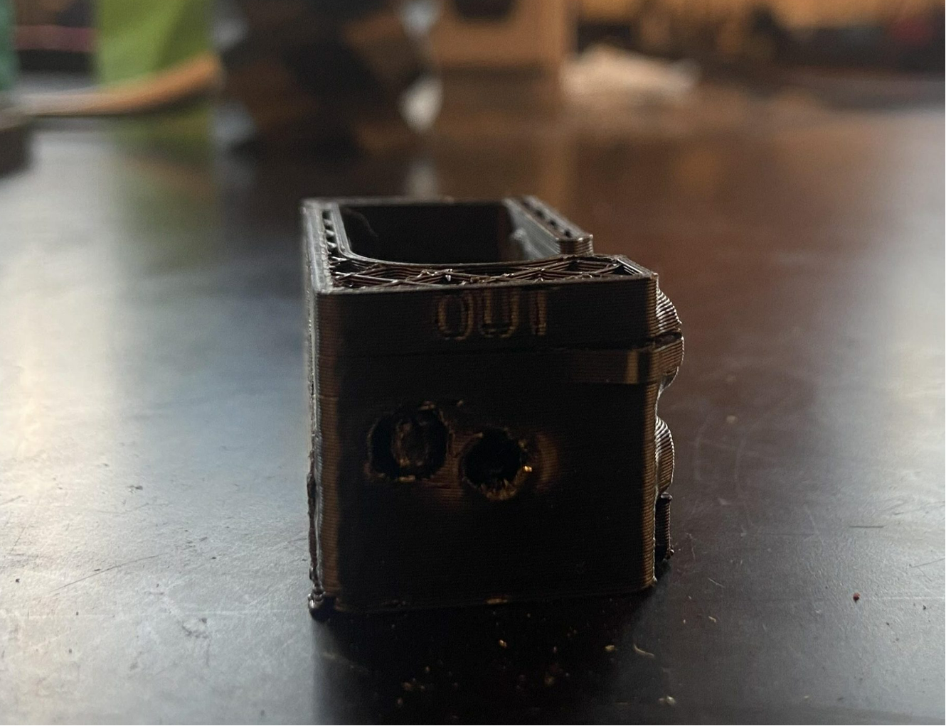
ABS print of the main sensor body
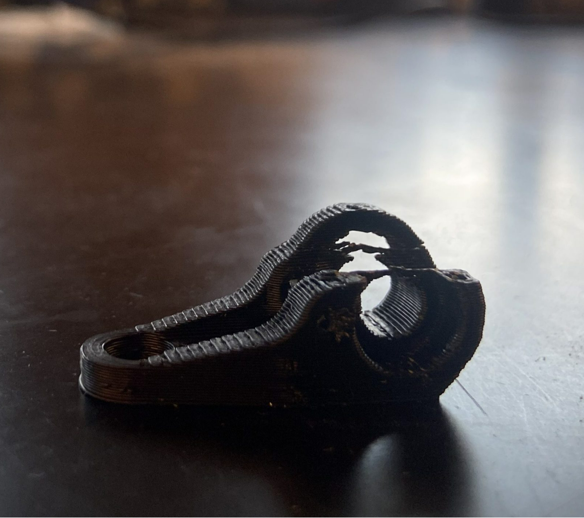
ABS print of the sensor lever
With the abs print having issues PLA filament was used instead of ABS filament. There were also issues with the printers that were used in which the filament feed rate and the thickness that was coming out the printer was not correct making the prints very fragile and brittle. After some time struggling with getting the prints of the sensor, the sensor was printed out and was ready for parts to be assembled.
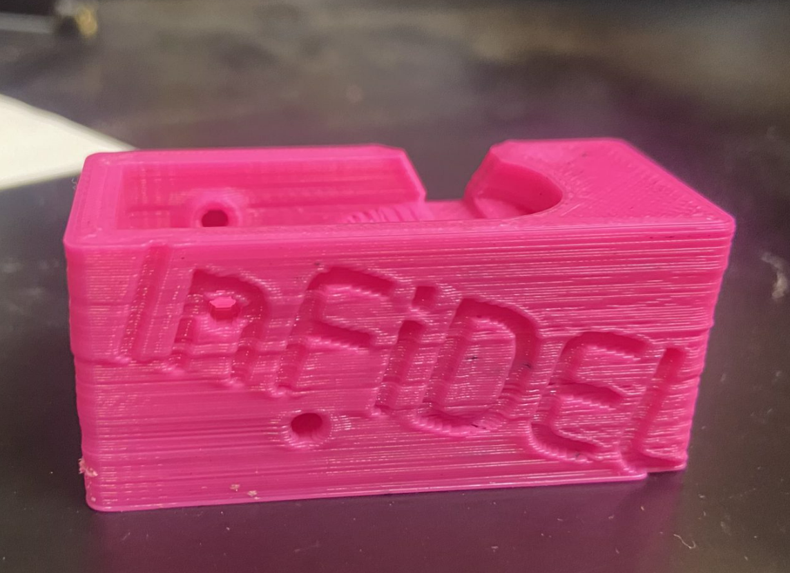
PLA print of the main sensor body
PLA print of the sensor lever
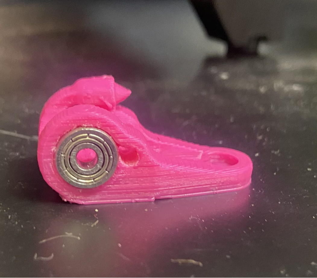
The assembly of the sensor was a long process. First with the lever the bearings that were inserted in figure 6 sometimes snapped the print in which the lever would have to be reprinted. After the bearings were in the lever of the sensor the main body was filed down and to be adjusted to handle the filament from Recyclebot. In which the sensor was readjusted to handle 1.75mm diameter with the variances that Recyclebot puts out. The linear hall effect sensor was attached to the main body of the sensor. In which gluing the linear hall effect sensor down was difficult since it was hard to keep the sensor in the right place. Then the main body was attached to the lever by a screw. The last step that was taken was putting the rest of the bearing pins and the spring used to reset the lever.
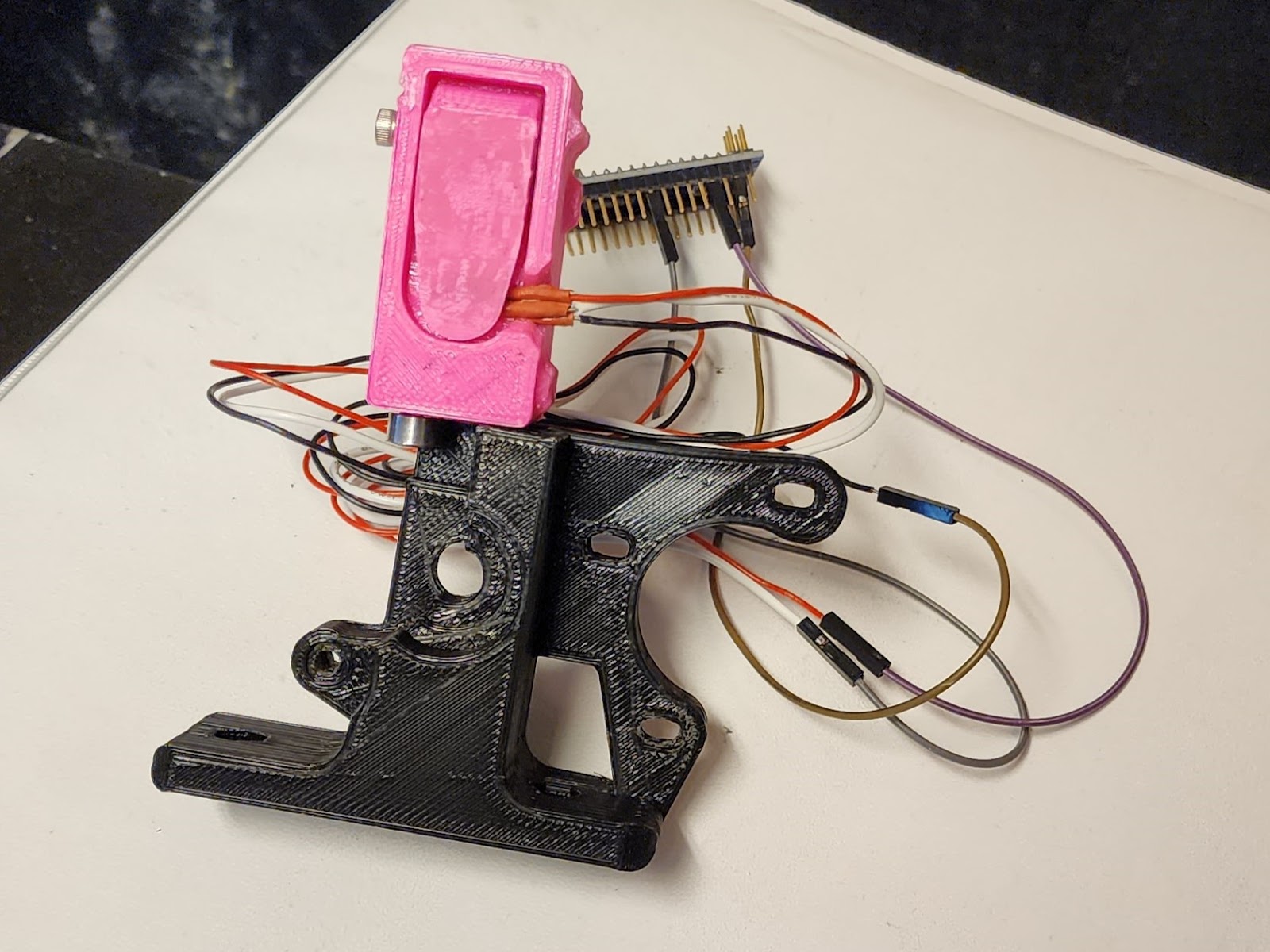
Fully assembled sensor
The last step is to calibrate the sensor by editing the Arduino code that was given. There were some issues in which the code was not initially fully understood so there was a ton of learning time with the code. In which there was a section of code that was not noticed for a period of time in which was used for the calibrations of the sensor. There was also a problem with how fast the sensor was changing making the output graph fluctuate greatly without the diameter being changed. In which an averaging function was put in to solve that issue. After putting in values for the calibration the sensor was working in which there was constant error of +/-0.02 mm.
While implementing this code with the stepper motor arduino code there was an issue in which the averaging function was creating a delay in which does not work with the circle buffer that was put in to handle the filament diameter sensor. In which would be fixed in a later part of the report.
Diameter Sensor Mount
A special mount was required to attach the diameter sensor to the 3D printer. The CAD files for the Lulzbot Taz 6 are available online, so the easiest mounting mechanism seemed to be to modify a part and print the new design.
Initially, the “idler” component was selected to be the modified component. It was decided against because it needs to move and there must be clearance above it in order to change filament. The placement would be inconvenient, potentially requiring the screws to be removed in order to change filament.
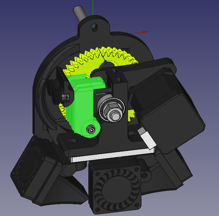
Idler (green)
The “extruder body” was selected instead. It remains stationary, is larger than the idler, and it already has filament running through it. There are no issues changing the filament because it is no longer obstructing the movement of the latch. The larger part means that there is more of an area for it to be attached to. The filament will not be subjected to any big changes in angle because the sensor will be in line with the path to the nozzle.
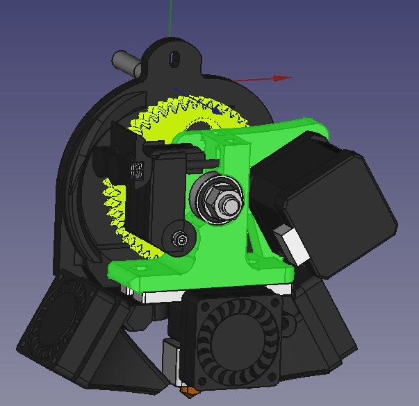
Extruder body (green)
The first design did not have anywhere to mount the electronics. This was because there was trouble editing the filament diameter CAD. The only provided file was an STL. We could only add material to it, not subtract material. This led to the inability to just include mounting holes for the electronics. The first attempt around this was to add an entire “holder” design from the internet for the electronics, however this was impractical. In the end, it was decided to create holes to mount the electronics onto instead. This was sleeker than the previous design.
Diameter sensor with mounting holes
This design was also scrapped because of time constraints. Only one hall effect sensor had been ordered and it was too late into the semester to order another in time. A new design was created to attach the existing filament diameter sensor instead of reprinting it (Figure 11). This new design is the most recent iteration and is currently in use. Unfortunately, this most recent design is not yet capable of having the electronics mounted to it.
Current diameter sensor mount
Software
Software development for this fall semester built upon the progress made in the previous semester. Last spring, interrupt service routines (ISRs) had been implemented to read the input stepper signals and determine the step frequency and direction based on period and signal phase. This period was then dynamically scaled and output to a stepper driver for driving the extruder stepper at the new, corrected frequency. A simple block diagram of this functionality is shown below.

One of the primary challenges of this project is accounting for the time difference between filament being measured and actually fed into the hot end for extrusion. The volume delivered to the hot end is the parameter that this project aims to finely control, but it is not possible to directly measure this at the hot end. To solve this, a 256-entry circular buffer was implemented which stores the measured filament diameter until it is recalled as that part of the filament reaches the hot end. Smaller, less-granular circular buffers may also be implemented but this size was particularly convenient because it exploits the inherent roll-over properties of an 8-bit integer counter.
The circular buffer data read/write index variable is incremented or decremented based on the number of output steps. If the assumption is made that no filament slip is present at the hobbed drive shaft, then the distance between the filament measurement system and the hot end can be expressed as a constant number of extruder steps. In our system, this was found to be approximately 5,980 steps by marking the point on the filament just before entering the filament measurement system, removing the filament, and using a caliper to measure the distance between the marked point and where the filament begins to melt in the hot end. The distance between the edge of the filament diameter sensor and its internal measurement wheel can be found from the 3D model and subtracted from this length. Lastly, the length (in this case, 128.00 mm) can be converter into a number of steps using the major diameter of the hobbed shaft (7.125 mm), the gear ratio of a Taz 6 extruder head (47:9), and the number of steps in a single revolution for the Moons stepper motor (200). With the length of the buffer in mind, this means the filament will need to be re-measured every 23 steps or every 0.5 mm.
This addition now leaves the code with two clocked loops running independently of one another. The first loop updates the period of the output clock every time a new input edge is detected. The output clock period is scaled according to the current measured diameter stored in the circular buffer. A second loop counts output clock cycles, and in this case every time 23 steps have been counted in the forward direction the buffer index is incremented one position and a new measurement is recorded from the measurement device. It is worth noting that if the extruder stepper rotates backwards the buffer index will decrement to point to a previous measurement that has been since overwritten and no longer correctly describes the diameter of the filament in the hot end. However, this was thought to only occur during momentary filament retractions during printing and in all these cases the extruder will subsequently run forwards at least the same number of steps and the correct data will be re-populated into the circular buffer.
Due to the precise nature of measurements required for this application, it is necessary to perform some averaging on the analog input from the filament measurement sensor to ensure the filament is correctly profiled; the system would not be effective at improving print quality if it was only adjusting filament flow rate based on measurement noise. The averaging technique used for prototyping the diameter sensor will not be effective in the final implementation because it relies on a delay function. This is problematic for two reasons; first, the code cannot accommodate any blocking functions like delay(), and second the time between measurements cannot be absolutely time-based because the frequency of output steps varies depending on printer operation. Instead, it was determined that the ADC will be sampled based on the number of counted output steps since the last sample. This allows the entire length of filament represented by one position in the buffer to be averaged together and also dynamically adjusts the ADC sampling rate to maintain the same number of samples per average measurement.
The interpolation lookup function was also modified from the one developed for testing the filament measurement sensor to optimize for efficiency and simplicity. The function used in testing had an input and output argument of type float, but Arduinos have poor native support for floating point operations and they can take as much as ten times longer to complete than equivalent integer math. As such, the input and output was changed to type integer, the same as is stored in the circular buffer. The lookup table was also modified to scale the measured diameter to an absolute 10-bit value on an equivalent scale of 1 V/mm if it was measured from an ADC. This absolute scale made understanding and processing of the data generally easier. Using 10-bit integers rather than floating point values was not thought to bring about a substantial decrease in accuracy in compensating for diameter variation. However, this assumption may need to be revisited if the filament diameter sensor does not provide enough voltage variation to obtain a large enough resolution on the 10-bit Arduino ADC.
Some additional functionality will also be required to ensure appropriate operation of the system. First, a saturation function will be used to limit the output frequency between 10 Hz and 3 kHz to prevent odd behavior and runaway if filament diameter measurements are erroneous for some reason. Furthermore, if an input edge is not received and two output pulses elapse, the output will be stopped to prevent over extrusion in the event the printer controller suddenly slows or altogether stops extrusion.
Feasibility Notes
Using the micros() function and interrupts to read the input signal was observed to result in period measurement accurate to ±6 µs. This yields a percent error of 0.006% at 10 Hz, 0.6% at 1 kHz, and 1.8% at 3 kHz. For context, a 10 Hz signal equates to a stepper output speed of 3 RPM or filament feed rate of 0.21 mm/s. Additionally, a 3 kHz input signal produces a stepper output speed of 900 RPM or a feed rate of 64.3 mm/s.
Timer 1 on the Arduino is a 16-bit timer and is implemented with a clock divider of 64; with an on-board system clock of 16 MHz, this yields a 4 µs timer resolution with a maximum period of 0.5 seconds (minimum frequency of 2 Hz) in phase-/frequency-correct PWM output mode.
Project Reproducibility
Currently the project is implemented on a breadboard for easy development and testing. However, this can easily be transferred to a perf-board as needed for final implementation on a 3D printer. A frequency generator and 24 VDC power supply are currently used to drive a spare stepper driver which emulates the stepper signals the microcontroller will be required to read from the 3D printer. The filament diameter sensor is also connected to the microcontroller on the breadboard. The microcontroller requires 5 V power from a laptop and outputs an adjusted frequency and direction signal to another stepper driver, which is supplied 24 V from the same bench supply and may be used to drive a stepper motor. When implemented on the printer, these 24 V and 5 V supplies will need to be sourced from the main printer drive board. The stepper drive signals to the extruder motor will also need to be re-routed into the microcontroller so the commanded frequency can be interpreted and modified. Screenshots of schematics for the breadboard circuit used in testing and the appropriate circuit for final implementation are included below. The full schematic files are also available in the OSF repository linked at the end of this report.
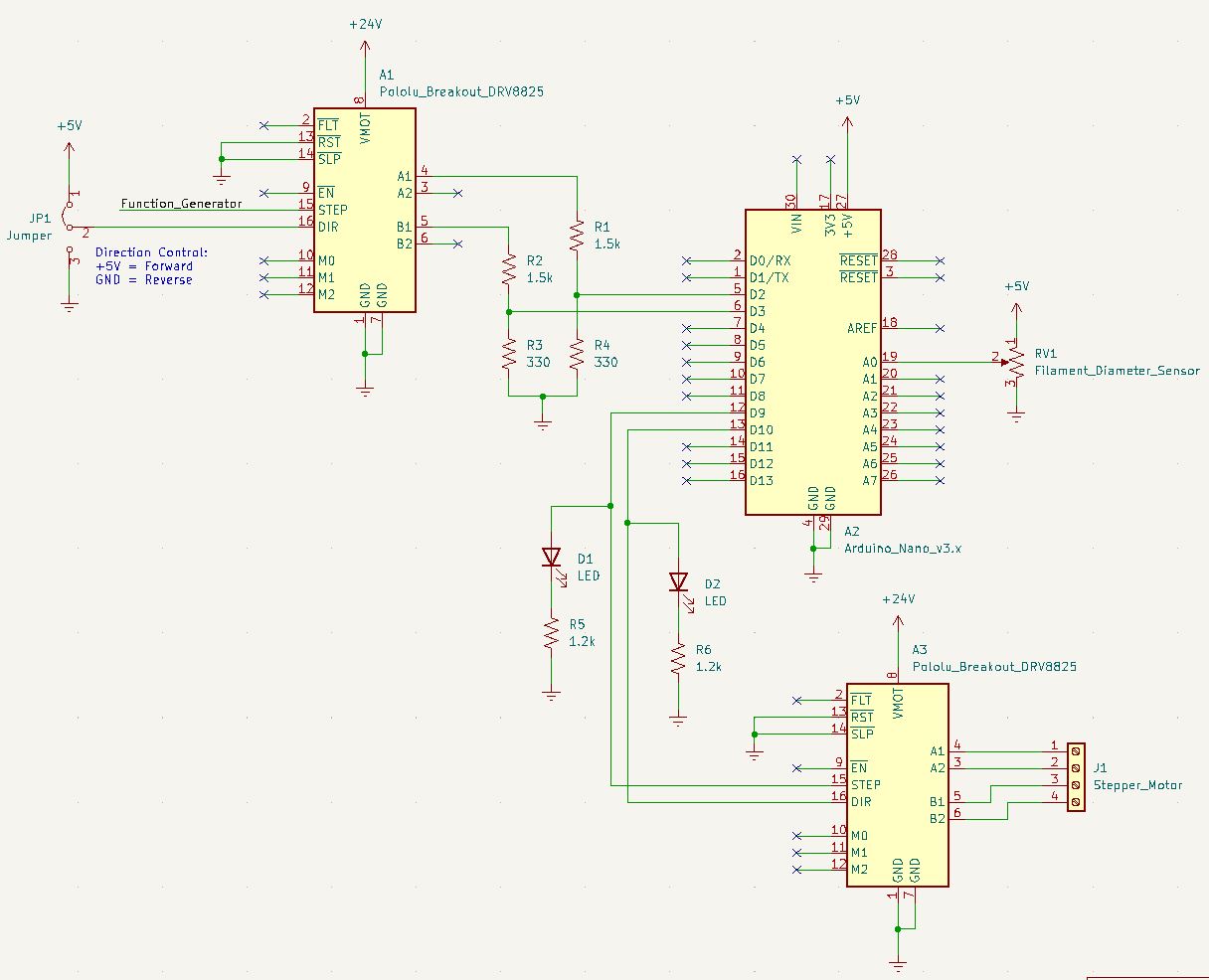
Schematic used for testing and software development with simulated stepper signals
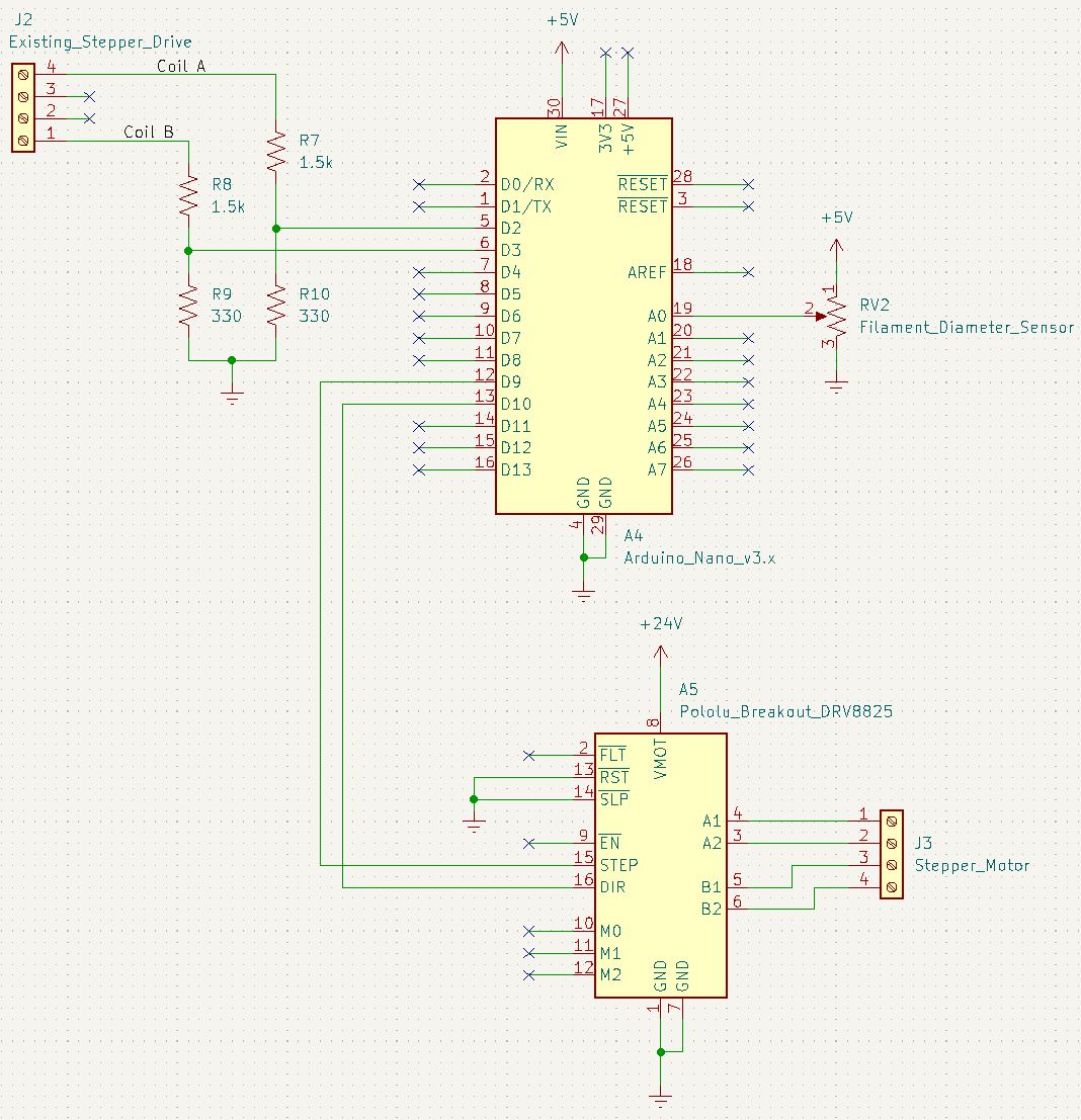
Schematic used for final implementation with stepper signals from controller
One substantial risk to this project is if the 3D printer controller uses micro-stepping as the software is not designed to understand this control scheme. Lulzbot Mini 2’s were observed to not use microstepping, but this has not yet been confirmed for Taz 6 printers. If microstepping is present, then this will need to be disabled in firmware (though this should be a readily available option).
With a physical test system assembled, the microcontroller can be flashed with the appropriate code and a filament diameter measurement system can be printed, constructed, and implemented. Due to the reliance on analog signaling, it would also be straightforward to implement a different filament diameter sensor than was used here if desired.
Open Sources Resources in this Design
| Open source projects related to 3D printer and Arduino | 3D Printer Extruders | Airtripper’s 3D Printer and Arduino Blog |
| Arduino IDE | https://www.arduino.cc/en/software |
| Lulzbot Taz 6.03 open source files | https://download.lulzbot.com/TAZ/6.03/ |
Bill of Materials
| Part Description | Manufacturer | MPN |
| Arduino Nano | Arduino | A000005 |
| Stepper Driver | Pololu | DRV8825 |
| Filament Diameter Sensor | https://www.printables.com/model/57154-infiDANK | |
OSF (Design Files Repository)