
Nic Cywinski(CpE-Senior), Adam Sandahl(CpE-Junior), Nick Sandahl(CpE-Junior)
______________________________________________________________________________________________
1.Project Description
Project Mission
The purpose of this project is to expand the Broadly Reconfigurable and Expandable Automation Device(BREAD) framework. The Barcode Utilization for Navigating Stock (BUNS) is our new “Slice” to the BREAD framework. The device will communicate and store data on barcodes scanned by a remote scanner. The basis of our project is to create an open source solution to tracking products as they move throughout a facility. This solution aims to create a system that logs the moving of multiple products at a single point in a line while remaining inexpensive.
BREAD is an open source project that uses ‘Slices’ to provide information to the centralized ‘Loaf.’ There are many different configurations that BREAD can operate in including single Slice operation, single Loaf usage, or multi Loaf usage. As the number of Slices for the BREAD framework increases, the number of applications for BREAD also increases. Therefore, by incorporating a Slice capable of barcode tracking, the potential usefulness of the BREAD framework is increased.
General Description
This device allows a production line to add an inexpensive logging device to help with the inventory management and cataloging of products or parts. This logging device would be capable of tracking the rate of products and track the count of each different product that the line may have. This system is broken up into 3 parts: Scanner, Slice, and Database. The scanner is a remote device that communicates the passing barcodes to the slice. The slice is the bridge between the loaf and the rest of the system. It will calculate the rate of products scanned while passing the barcode data to the database. The database will store data on the different products a line has and will utilize a network GUI to display the data and allow user input.
2.Functional Requirements and Methodology
- The entire device will have design files originated entirely from free and open source software. Complete ✔
- Our project uses all open source software and easy to obtain hardware such as Arduinos and a Raspberry Pi. The software that we are using includes: Arduino IDE, Python, Apache, MariaDB, phpMyAdmin, php, and html. All code that is developed throughout the project will be provided in the OSF repository linked throughout this report.(such as here)
- Hardware will be created to scan a barcode. Complete ✔
- To scan a barcode, we created a couple of different options, our best performing being the stationary Mountable Scanner, which uses the ‘Maikrt Embedded QR Code Scanning Module’ and an arduino to process and send the data to the receiver.
- Scanner will have a PCB and 3D printed enclosure. In Development
- We are still working on the PCB however, a 3d printed enclosure has been designed and printed to house the mountable scanner.
- A database will be developed to store barcode data. Complete ✔
- The backend design of the database has been designed and implemented successfully and as it stands now, we are not having any issues and don’t see any limitations with the current implementation.
- The scanner will communicate with the database. Complete ✔
- The scanner is able to recognize a barcode, interpret it, then send it to the receiver, which is then uploaded to the database to be displayed on the GUI.
- An interface will be developed to view the database. Complete ✔
- A rudimentary interface has been developed allowing a user to view the database in a specific table.
- GUI will be able to add item descriptions to the database. Incomplete
- This is a task dedicated to next semester and we do not see any limitations on this goal as of now.
- The slice will compute the rate of production. Incomplete
- This is a task dedicated to next semester and we do not see any limitations on this goal as of now.
- The rate will be communicated to the Loaf. Incomplete
- This is a task dedicated to next semester and we do not see any limitations on this goal as of now.
- The slice will have a 3D printed enclosure. Incomplete
- This is a task dedicated to next semester and we do not see any limitations on this goal as of now. We will be considering the footprint of the slice and making any changes necessary which may include removing the slice Arduino, or changing the communication type between the Pi and Arduino.
- The database GUI will be accessible through IOT devices. Incomplete
- This is a task dedicated to next semester and we do not see any limitations on this goal as of now.
Value-Added Goals
- A second scanner will be created. Incomplete
- We began working with a different scanner type, one more accessible and cheaper to buy, but are having difficulty with the scanner properly communicating with the local arduino.
- The scanner will operate on a battery charge. Incomplete
- This coincides with the portable scanner as you wouldn’t want to drag around a power cable around a factory floor.
- A mounting rack for the scanner will be created. Incomplete
- We would eventually like to implement some mounting hardware for the mounted scanner as the 3d case is designed with this in mind.
- Manual number input. Incomplete
- This idea would be meant for itemizing products whose barcodes are damaged and unreadable. This would give the user the option to manually type in a barcode unsteady of scanning it.
- Screen on scanner. In Process
- Currently the screen only shows the data that the barcode contains. Eventually, we want the screen to show a variety of information including how many items of that product are in stock, or the description of the product for example.
3.Future Work
For future work, our first priority is to reconfigure the database such that more information can be stored in the table. Our goal this semester was to prove that the scanner can upload the barcode reliably. Now, we need to allow the user to edit the database to provide more information about the product including the name, quantity, location, description,…. To do this, the GUI needs to be improved to allow for this.
Our next priority is to integrate this slice into the BREAD framework. A decision will be made as to what will be the most important information to provide for BREAD. Our current idea is the rate at which something is being produced/entering the factory, but we spend a bit of time discussing this.
Another priority will be removing the Arduino on the main slice to reduce footprint size and cost of the device. If we are unable, we will be switching from USB communication to some other protocol between the arduino and Raspberry Pi to reduce the slice footprint. This would also include manufacturing a PCB for the slice. By this time, our mountable scanner will be finalized, and a PCB can be created for that as well.
If all of this gets completed, our focus will turn to our value-adding goals which would enhance the use case and viability of BREAD BUNS.
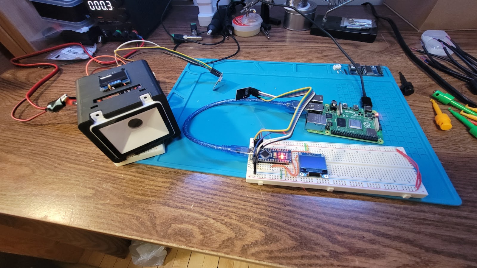
4.Device Operation
For current device operation, provide power to the raspberry pi which provides power to the Arduino and receiver antenna setup. Provide power to the mountable scanner and wait for the raspberry pi to connect to WiFi. At this point, you are able to navigate to the database viewer by going to either http://localhost/ if you are using a web browser on the pi, or the viewer can be seen by typing in the ip address of the Pi in the url ensuring that the device you are using and the Pi are on the same wifi network. As new barcodes are scanned, refresh the webpage to see the data that was encoded in the barcode.
5. Replication of Work
This section is split into different sections detailing on what specific portion of the BUNS framework that someone may want to replicate. These include the Mountable Scanner, Portable Scanner, and the BUNS Slice with database creation.
Mountable Scanner:
The mountable scanner is built around an embedded barcode scanner. The scanner sends the code to an arduino nano that wirelessly transmits it to the database on the slice.
| Part | Component Number | Supplier | Quantity | Cost per Unit | Total Cost |
| Arduino Nano | A000005 | Arduino | 1 | $24.90 | $24.90 |
| Embedded Barcode Scanner | Amazon | 1 | $45.99 | $45.99 | |
| NRF24l01 | Amazon | 1 | $1.97 | $1.97 | |
| 0.96 In OLED | Amazon | 1 | $2.58 | $2.58 | |
| 3D printed housing | 3D printed | 1 | <$1 | <$1 | |
| Total: | $76.44 |
Table 1: Mountable Scanner Bill of Materials
The components are all wired to the arduino nano. The wiring diagram is shown below.
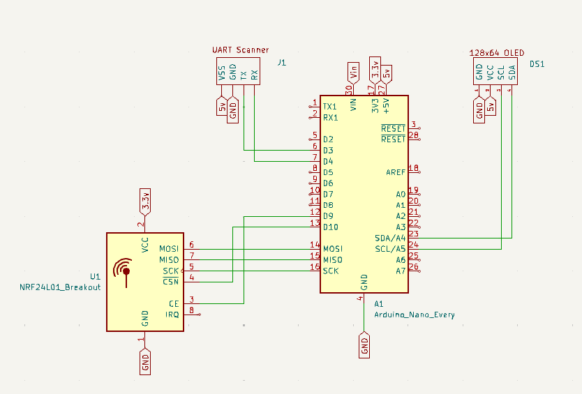
Figure 1: Wiring diagram for mountable scanner
Scanner:
The scanner is powered off the arduino’s 5v line and gnd.
The scanner’s Rx pin is connected to the arduino’s pin D4. Pin D4 is configured in code to be the arduino’s serial transmit, Tx.
The scanner’s Tx pin is connected to the arduino’s pin D3. Pin D3 is set up as the arduino’s receiver, Rx.
NRF24l01:
The NRF24l01 is powered off the arduino’s 3.3v line and gnd.
The CE pin is wired to pin D9 and CSN to pin D10.
CE and CSN are configured in code and can be changed to any digital pins.
MOSI to pin D11 and MISO to pin D12.
SCK to pin D13. These 3 pins are the communication pins on the arduino nano.
OLED display:
The display is power off the 5v line and gnd.
SDA is wired to pin A4 and SCL to pin A5.
These 2 pins are the I2C communication pins for the arduino nano.
Code: Using a computer that has the arduino IDE installed. Download BreadBunsStationaryScanner code. Plug your arduino nano into the computer. Using the arduino IDE, open the BreadBunsStationaryScanner code. Make any changes to pin assignments if you use other pins than the diagram. Using the tools menu select the arduino nano as your board and choose the COM port that you plug the nano into. Upload the code to the nano.
Housing: 3D print the stationary Scanner’s housing. Mount the scanner on the front of the housing. The display mounts on the top of the housing. It can face towards or away from the scanner. Insert the remaining electronics and close the back.
The scanner is powered by a usb power bank that mounts to the back of the housing and is plugged into the nano.
Portable Scanner:(Incomplete)
The portable scanner enables usb hid barcode scanners to be integrated. This uses a usb to serial module that uses the same hardware and code as the mountable scanner to connect to the slice.
| Part | Component Number | Supplier | Quantity | Cost per Unit | Total Cost |
| Arduino Nano | A000005 | Arduino | 1 | $24.90 | $24.90 |
| usb Barcode Scanner | Amazon | 1 | $13.95 | $13.95 | |
| Usb to serial module ch375b | Amazon | 1 | $7.99 | $7.99 | |
| NRF24l01 | Amazon | 1 | $1.97 | $1.97 | |
| 0.96 In OLED | Amazon | 1 | $2.58 | $2.58 | |
| 3D printed housing | 3D printed | 1 | <$1 | <$1 | |
| Total: | $52.39 |
Table 2: Portable Scanner Bill of Materials
Same tutorial as the mountable scanner but without the embedded scanner and replaces it with the usb to serial module:
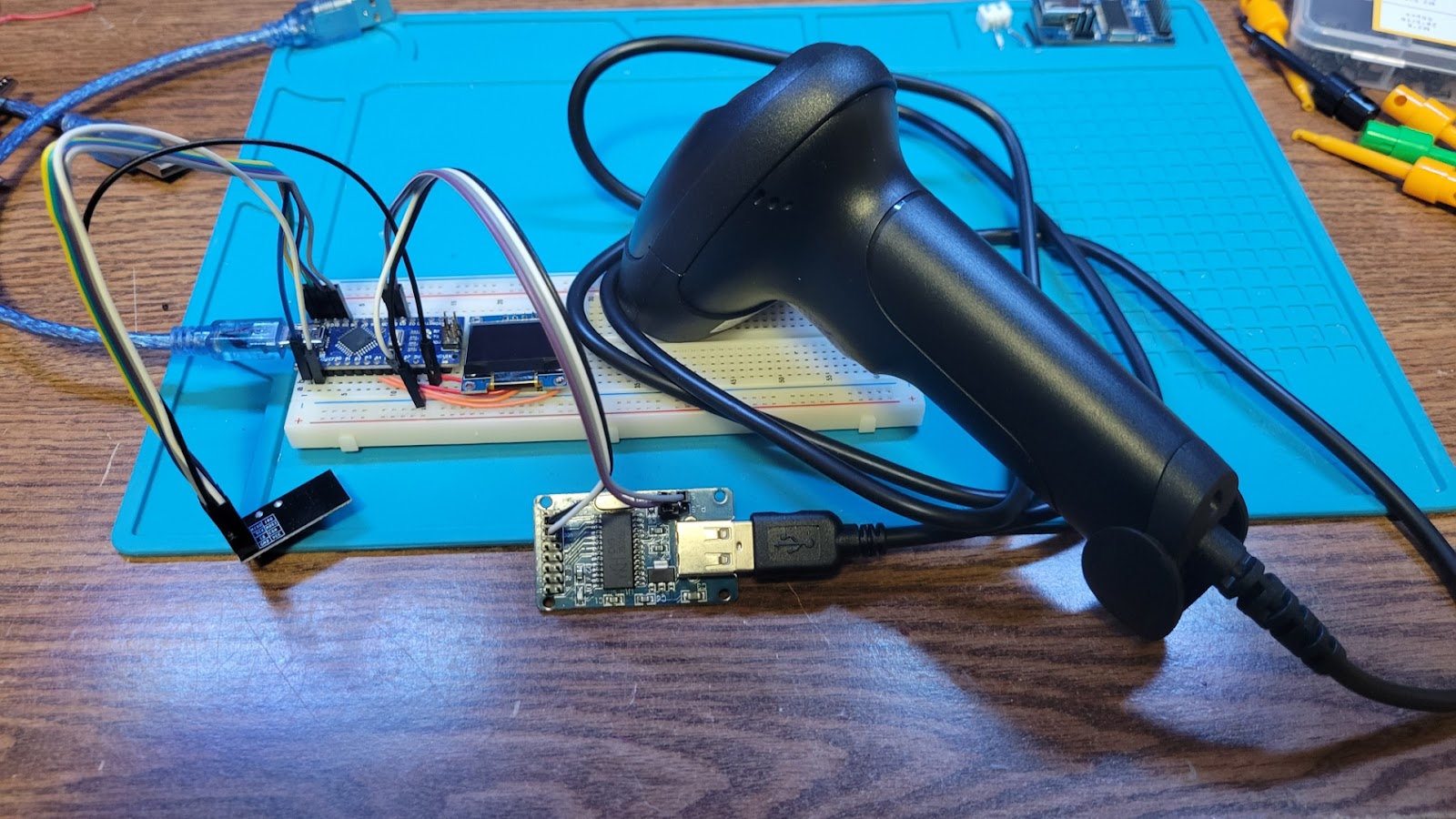
Figure 5: Portable scanner prototype
BUNS Slice and Database:
The slice serves as the central hub for all barcode receiving. The receiving hardware consists of the NRF24L01 antenna and the arduino. The arduino then sends the barcode information to the Raspberry Pi over a USB connection to upload into a database. This database is then made accessible over an html webpage. This section will describe how to set up the Raspberry PI as a database, connect the Arduino, read from the arduino, and create a webpage to view the table.
| Part | Component Number | Supplier | Quantity | Cost per Unit | Total Cost |
| Arduino Nano | A000005 | Arduino | 1 | $24.90 | $24.90 |
| Raspberry Pi 4 | Amazon | 1 | $61.75 | $61.75 | |
| NRF24l01 | Amazon | 1 | $1.97 | $1.97 | |
| 0.96 In OLED | Amazon | 1 | $2.58 | $2.58 | |
| 3D printed housing | 3D printed | 1 | <$1 | <$1 |
Table 3: BUNS Slice Bill of Materials
- Using the Raspberry Pi imager, configure the SD card as recommended by the software.
- Make any necessary updates to the Pi by running the ‘sudo apt update’ and ‘sudo apt upgrade’ commands in the terminal.
- Ensure that the latest version of python is installed with python-serial. Do this by running the following command: ‘sudo apt-get install python3 python3-serial’
- Install Apache, and HTTP Web Server Software, and the necessary packages by running ‘sudo apt-get install apache2 apache2-doc apache2-utils’ in the terminal.
- Install MariaDB a MySQL database management system by running ‘sudo apt-get install mariadb-server mariadb-client’ in the terminal.
- At this point, you can check and see if your raspberry pi is running the web server by going to a web browser on the Pi and navigating to http://localhost/, or with a different device on the same wifi network and typing the ip address of the raspberry pi in the search bar. If your web server is configured correctly you will get the default page from Apache that looks like this:
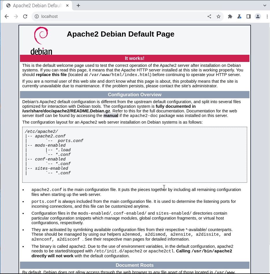
Figure 6: It Works Default Page for Apache
- To test your MySQL database, and create the super user for the database(MAKE SURE YOU REMEMBER THIS) run the command ‘sudo mysql -uExUsername -pP@sw0rd
- The above example sets the super user’s username and password to ‘ExUsername’ and ‘P@sw0rd’ respectively. These can be anything so long as you remember them.
- If your MySQL database is configured correctly, you will enter the MySQL terminal displaying the connection number and Server version. Exit the MySQL terminal by typing ‘exit’ and it will return you to the main Raspberry Pi terminal.
- Install phpMyAdmin to help with database management by running ‘sudo apt-get install phpmyadmin’ in the terminal.
- At this point there will be a couple of different pop ups. The order may be different but the entries will not change.
- For any of the pop ups asking for a username and password provide the same information for the created user from step 5b.
- Select apache2 using the space bar and hit OK by using tab and enter.
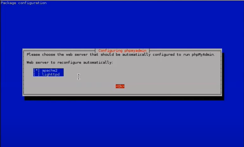
Figure 7: Web Server Configuration 1
- Select ‘Yes’ for the following pop up using the enter button and arrow keys.
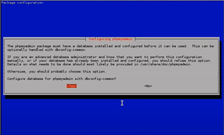
Figure 8: phpMyAdmin Configuration
- Install php and a couple of libraries by running ‘sudo apt-get install php libapache2-mod-php php-pear’ in the terminal
- The next step is to reconfigure the apache2 configuration file. You can navigate to this file by typing: ‘sudo nano /etc/apache2/apache2.conf’ and then hit enter.
- Navigate to the end of the file and beneath all of the other text, type ‘Include /etc/phpmyadmin/apache.conf’ exit the file by hitting ctrl+x then y then enter.
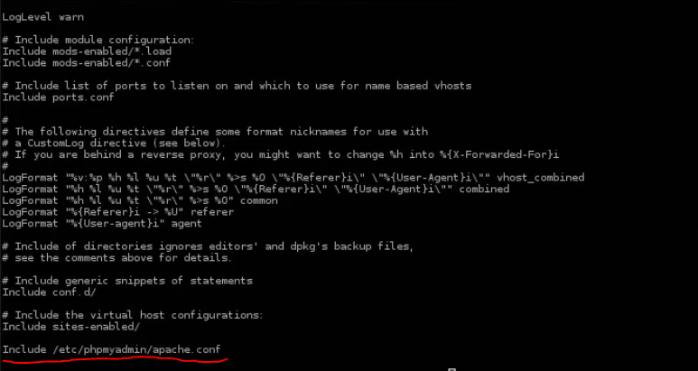
Figure 9: Apache2 Configuration File.
- Restart the apache application inorder for these changes to take effect. Do this by running ‘sudo /etc/init.d/apache2 restart’ in the terminal.
- Go back to the browser and navigate back to http://localhost/ or the ip address, and append the url with phpmyadmin/. i.e. http://localhost/phpmyadmin/. You will see the phpMyAdmin welcome page if everything is configured correctly.
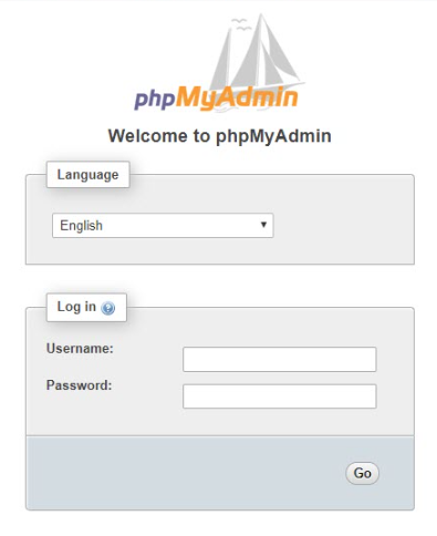
Figure 10: phpMyAdmin Welcome Page
- Enter in the username and password that was created in step 5b and you will be brought to the phpMyAdmin home page.
- Create a new database and table to store the values into. For BUNS, the database is named ‘testdb’ and the table name is ‘count’. If you would like to use different names, make sure to update the code that is reading the Arduino Serial output(usb.py), and the code that is displaying the table to the webpage(index.php/connection.php). The code has comments describing all variable names and it is provided in the OSF repository that is linked here.
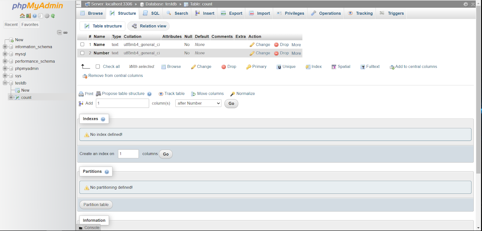
Figure 11: phpMyAdmin Table Configuration
- In phpMyAdmin, configure the table with 2 columns named ‘Names’ and ‘Number’ with an input of text. These can also be named whatever you would like but make sure to update both usb.py, index.php, and connection.php.
- Speaking of which, it is now time to implement these files, place usb.py in the home directory and index.php and connection.php need to be placed in the directory at /var/www/html overwriting the default index.php file that we saw in step 5a.
- Go through all 3 code files and update the necessary information as described in the code comments.
- Flash the Arduino using a different computer or using the Pi if you would like. Hook up the receiver arduino to the Pi over USB ensuring that the correct usb channel has been identified in usb.py and make sure that the delimiters that the Arduino is printing matches that of usb.py.
- Go back to the raspberry pi terminal and run the usb python program using ‘python ./usb.py’
- As the arduino sends data over, you will see numbers populating the phpMyAdmin table. (you will need to refresh the page). Now, go back to https://localhost/ (or the ip url) this page should now be replaced with the rudimentary GUI interface that displays all current table entries.
- To start the python program once power is supplied to the slice, type ‘sudo nano /etc/rc.local’ and in the line above ‘exit 0’ type “sudo bash -c ‘python /home/buns/usb.py > /home/buns/buns.log 2>&1’ &” replacing the file paths with your respective location for the program and where you would like a log file with all of the program outputs.
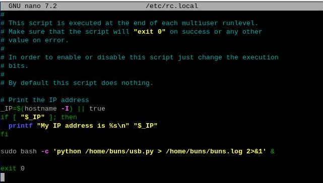
Figure 12: Run usb.py on Startup
6.Cost Comparisons
Researching for other barcode inventory management systems we came across 2 very popular options for small to medium sized businesses that had monthly subscription plans. The two companies we found with similar operations to BUNS are Sortly and Cognex. Sortly uses the camera from a smartphone or tablet to communicate with the database with a $59 monthly subscription fee, and Cognex makes stationary scanners in the range of $1500. In comparison, BUNS costs around $120 depending on what configuration is used as described in the replication section of this report. With Sortly, you are also limited in the number of items that you are allowed to have in your inventory; this is capped as 10,000 items for Sortly with the option to upgrade upon paying a larger monthly service fee. Another drawback is the lack of customization for these professional inventory management systems as only 25 custom fields are allowed in the Sortly.
The cost of BUNS can be greatly reduced without the use of a raspberry pi and replacing it with a different computer. If you truly wanted a low-cost solution, this would be one way to do it. This would mean having a computer in a centralized location to allow for the scanners to send data to it, and hosting the webserver on the computer. By removing the Raspberry Pi, the cost of BUNS would be cut in half.
7. Additional Resources
- https://www.sciencedirect.com/science/article/pii/S2468067223000743
- info about BREAD
- https://pimylifeup.com/raspberry-pi-mysql/
- SQL database on Pi
- https://howtomechatronics.com/tutorials/arduino/arduino-wireless-communication-nrf24l01-tutorial/
- nRF24L01 description
- https://linuxhint.com/connect-arduino-nano-to-raspberry-pi/
- Arduino and Pi USB communication
- https://www.tomshardware.com/reviews/raspberry-pi-headless-setup-how-to,6028.html
- Raspberry pi set up configuration