
KeWee Energy Meters is back and better than ever! This semester has been largely devoted to a reworking of both our sensing method and our choice of Arduino, with the launch of the new Arduino Nano ESP32 last fall that is much better suited to our project. Below is our final report for the Spring of 2024.
Quick Links
Main Product Images
Project Description
The KeWee Energy Meters project aims to create a series of devices and software for home energy monitoring. We seek to make affordable sensors and IoT devices that can communicate with a central or self-hosted web server for storing data. We also seek to design a website for users to access their device information and share it with others. Our project has been ongoing since January 2022, and is expected to continue for at least a year or more into the future as this project has many areas prime for growth and development.
Methodology in Brief
The methodology to recreate our project comes in three parts. The first part is the physical hardware / circuit design / PCB assembly / enclosure. The second part is the Arduino IDE setup for dependencies and compiling the source code. The third part is self-hosting a custom NGINX web server with a website and database. The first is extensively discussed here, while the remaining parts are discussed as part of Assembly Instructions (formerly known as our Steps to Reproduce section).
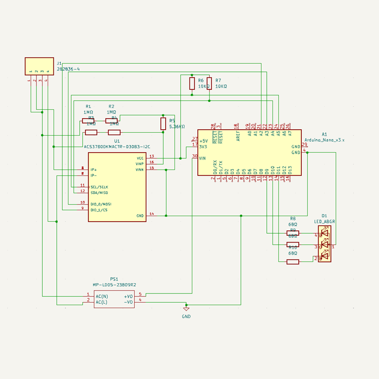
This project uses the ACS37800 (ACS37800KMACTR-030B3-I2C) current sensor for all measurements. This sensor communicates with the microcontroller (Arduino) via I2C and has several measurements that can be accessed. The Kewee Meter uses a similar circuit to the typical application suggested in the current sensor’s datasheet, shown in Figure 2.
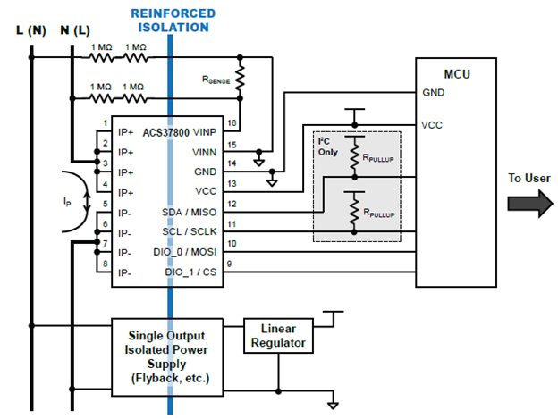
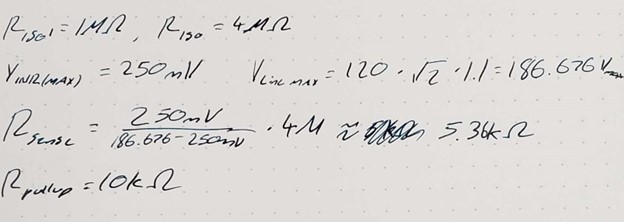
The value of RSENSE is calculated based on the peak expected voltage, so that the current sensor can adjust its calculations to fit the optimal range for an application. The calculation for this application is shown below in Figure 3. If you need to sense a different voltage range, use the datasheet to calculate your correct resistance (see “CONFIGURING THE DEVICE FOR AC APPLICATIONS” on page 19 – 20 of ACS37800 Datasheet). KeWee meters uses 10 kΩ resistors for the pull up resistors.
The only other difference in our circuit is that we have chosen to tie DIO_0 and DIO_1 to Vcc to communicate the correct I2C address, since those digital IO pins are going unused in our current design. The final schematic is shown below in Figure 4. We are using the Arduino Nano ESP32, but this design can be adapted to any microcontroller.
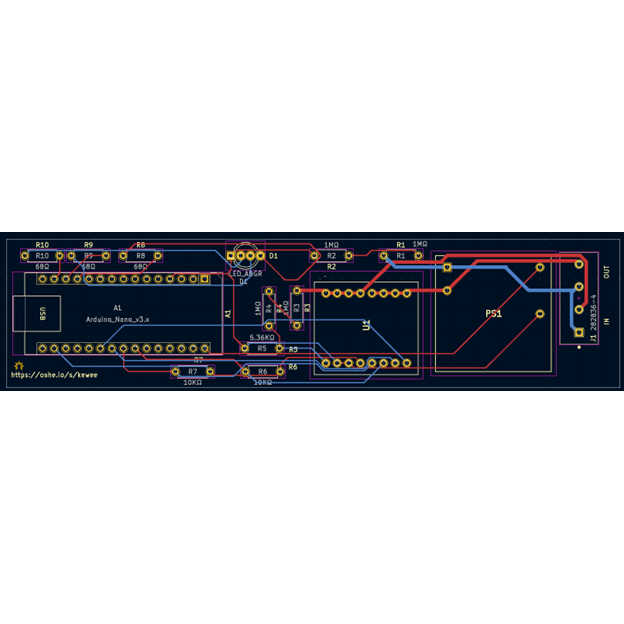
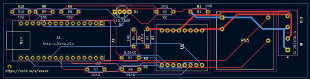
Using the KiCad PCB file provided in the OSF Repository and shown in Figure 5, the user will be able to generate the appropriate Gerber files if the provided Gerber and drill files are not functional. Two layers are being used for this design for simplicity and to make it easier to manufacture either via a third party or the user’s own personal mill. The routing that is directly connected to the line and neutral 120Vac has been thickened to .75mm and protected by an outside fuse.
As shown in Figure 5, R10, R9, and R8 are shown as 68Ω resistors however the user may swap them for a dimmer or brighter led depending on the value chosen. Also something that is not shown on the PCB are the Line and Neutral ports which are shown as the Neutral port closest to the dot on the phoenix connector and the Line port being the one just above Neutral. All resistors being used are 1/4W as the current is not enough to cause any resistors to burn up. When submitting PCB to JCLPCB make sure that the drill files as well as all required layers are included with the .zip file that is sent.
This PCB is designed to have the Arduino Nano, 1/4W resistors, led, phoenix connector, and power supply soldered onto the board itself, however the ACS37800 IC uses a SOIC16W adapter as shown in the Bill of Materials which allows for easier swapping in case the fuse built into the IC burns up. When soldering the ACS37800 be sure to use flux to prevent connecting the small copper pads that are on the SOIC16W adapter together.
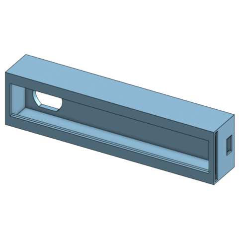
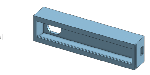
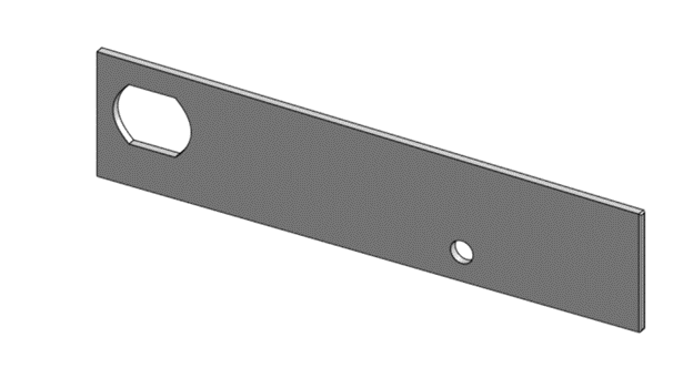
Also designed this semester was an enclosure with cover to fit the PCB as shown in Figure 6 and Figure 7. While ordering and shipping issues plagued our PCB and prevented a test fit into this enclosure, it is still a good baseline with some adjusting likely needed.
Bill of Materials (BOM)
| Name | Description | Individual Cost | Quantity | Total Cost | Purchase Link |
| Arduino Nano ESP32 | Used to communicate with the power monitor, perform calculations, and provide a self-hosted server | $20.00 | 1 | $20.00 | Arduino Nano ESP32 |
| ACS37800 Power Monitor | IC that measures voltage and current and communicates via I2C. | $7.27 | 1 | $7.27 | ACS37800 Power Monitor |
| LCQT-SOIC16W Socket | Socket to adapt the power monitor from surface mounted to through hole. | $4.75 | 1 | $4.75 | LCQT-SOIC16W Socket |
| LD05 AC/DC converter | Converts AC voltage to 9 V DC. | $4.53 | 1 | $4.53 | LD05 AC/DC Converter |
| 1 MΩ Resistor | Resistor used to reduce the current going to the power monitor. | $0.24 | 4 | $0.96 | 1 MΩ Resistor |
| 5.36 K Ω Resistor | A resistor used to adjust the voltage range measured by the power monitor. | $0.10 | 1 | $0.10 | 5.36 K Ω Resistor |
| 10 K Ω Resistor | Resistors used for the pull up resistors of the SDA and SCL lines of the power monitor | $0.10 | 2 | $0.20 | 10 K Ω Resistor |
| 21 A 300 VAC Fuse | A Fuse that will be used to protect the device from overcurrent from a wall outlet | $8.85 | 1 | $8.85 | 21 A 300 VAC Fuse |
| Molded Base Fuse Block | Used to hold the fuse and allow the fuse to be replaced without any soldering. | $1.45 | 1 | $1.45 | Molded Base Fuse Block |
| Phoenix Connector | Connects power from an outlet to the device | $1.00 | 2 | $2.00 | Phoenix Connector |
| 3D Printer Filament | Filament for a 3D printer, a variety of kinds can be used this project is using PLA plastic | ||||
| COM-12986 | RGB LED | $3.50 | 1 | $3.50 | COM-12986 |
| 68Ω 1/4W Resistor | Pullup resistor for RGB LED | $0.10 | 3 | $0.30 | CF14JT68R0 |
| PCB | Printed Circuit Board Prototype manufactured by JLCPCB | $5.70 | 5 | $1.14 | JCLPCB |
Tools Used
Note that not all of these tools are strictly required to reproduce this project, but were used in its development.
- Arduino IDE
- KiCAD
- Agilent Oscilloscope
- Multimeter
- Breadboards
- Agilent DC Power Supply
- Variac Variable Transformer
- Onshape
- Cura Lulzbot Edition
- Soldering Equipment
Assembly Instructions
Part 1: PCB and Circuitry Hardware
- Print or order the PCB online (we ordered through JLCPCB) using the Gerber Files provided in our OSF repository.
- Determine if you need a different RSENSE value. If you are measuring a 120 VAC outlet, use the value in the schematic and BOM.
- Solder the correct components to the board, as labelled in the schematic.
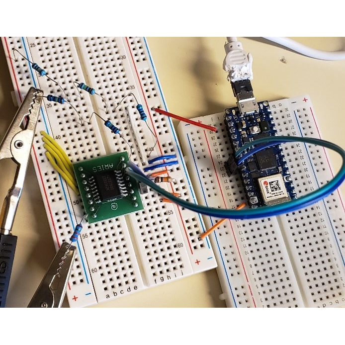
- NOTE: If you are unable to print the PCB design it is possible to follow this design using a breadboard, as seen in Figure 1, though it is not recommended.
Part 2: 3D Printed Enclosure
- Download slicer software that is compatible with whatever 3D printer is being used. The OSHE lab uses Lulzbot Cura printers, so Cura Lulzbot Edition software was used.
- Upload stl files to the slicer software adjust the settings to match the printer and filament being used.
- Print each part at a time and when it is done printing place the components inside the enclosure and slide the printed cover onto the slot
- Feel free to adjust the dimensions of the enclosure if needed using this copy of the 3D model Kewee Enclosure Copy.
Part 3: Arduino Software
- Install the latest Arduino IDE (2.X.X) from https://www.arduino.cc/en/software
- Download the source code/sketch folder for the Arduino Nano ESP32 from our OSF Repository (download the entire “OSHE_KeWee_Arduino_24H1” found in “Arduino – Source Code”).
- Open the “OSHE_KeWee_Arduino_24H1.ino” project file in the Arduino IDE.
- In the Boards Manager tab, install Arduino ESP32 Boards.
- Connect the Arduino Nano ESP32 via USB-C to your computer.
- Verify and upload the code to the Arduino.
- NOTE: Be sure to double check that the KEWEE_SENSOR_R_ISO and KEWEE_SENSOR_R_SENSE match the resistors in your circuit. The former is the sum of each isolating resistors (typ. 4 MΩ) and the latter is the sensing resistor value. It is recommended that you measure these resistances with a multimeter to ensure the greatest sensing accuracy.
To actually get data uploading to the server (once you’ve set that up), return here and follow these instructions:
- Use the server’s debugging page for “Test_Device_RegisterNewDevice.html” (found in www_root_directory/demonstration-and-debugging-files/) to register your device and assign it to your user account with the server.
- The serial number should be a 10-digit number (do not start with a zero)
- The MAC address should be for your specific Arduino (lowercase hexadecimal).
- When you submit, make note of the token you are given, you will need that later to authenticate your Arduino with the server. (While yes, authentication is occurring here, this is NOT secure. See the disclaimer in the source code header comment for more information.)
- Change the IP address on line 99 to match your server’s IP address.
- Change the MAC address, serial number, and token values to what you used/found earlier. See Figure 8 for these lines of code, with highlights showing what parts to change specifically.

Part 4: Self-Hosted Server Software
The server software still has largely the same setup process as in semesters prior. If you have a self-hosted instance running already, besides doing your own Nginx, MySQL, PHP, and OS updates, all you need to do is download an updated copy of the root WWW folder from the OSF Repository and overwrite the files currently in your WWW directory. Note that if you have existing meters, be careful, new database structure changes have been made that might cause issues or data loss. Always make a backup before attempting any upgrades. For those looking to set up a self-hosted server for the first time, the instructions are included below.
- Set up a computer or virtual machine with a Linux distribution of your choosing (we recommend an LTS branch of Ubuntu). Alternatively, find a hosting provider for a LEMP stack server.
- Install Nginx, MySQL, and PHP on that system.
- We recommend following a guide based on the most recent LTS version of Ubuntu.
- At the time of writing, Ubuntu 22.04 LTS can be configured following the guide linked in the Server Resources section.
- As the last part of setting up the LEMP stack, create a MySQL database and keep track of the name for use later (when in the mysql terminal, type “CREATE DATABASE <insert database name>;”).
- Load the contents of “WWW Root Directory” into “/var/www/” and follow the article in how to configure Nginx to appropriately access this directory.
- The site name is just for Nginx to be able to reference, it is not actually changing the published domain (which is not covered by this tutorial, we only operate within a local network at the time of writing.)
- Load the contents of “Database Creation Scripts” into an easily accessible directory on your system. Make sure this directory is not published. We recommend just placing it in your user account’s desktop directory.
- Modify the “Create_User_MYSQLTestUser.sql” file to replace any redacted data with the relevant credentials you’d like to have for your new database.
- If the command structure / meaning of items is unclear, please reference a tutorial on SQL. We highly recommend W3Schools.com and link to them below.
- Modify the “/var/www/libraries/security/kewee_credentials.php” to contain the credentials created in the last step.
- Please note the warnings in these files, this is not an ideal security practice and should be replaced by some better method for allowing local scripts to access a database.
- Modify the “/var/www/libraries/security/kewee_crypt.php” to contain a password hashing algorithm of your choice.
- If you are unsure of the options available to you, please see the linked PHP Documentation for more information regarding the password_hash() and password_verify() functions.
- After connecting to your newly created MySQL database from a Linux terminal (“mysql”, then “connect <insert database name>;”), use the “source” command (type “help” once in MySQL for more info) to execute the three “Create_<table/user/etc>.sql” files from the “Database Creation Scripts” directory. These will create the “Users” and “Devices” tables, as well as allow all scripts to access the database with the variables in “kewee_credentials.php”.
- Now, you should be ready to connect! The server will be hosted at http://localhost or whatever your LAN IP address is.
- Note, before port forwarding and publicly hosting your server, you should configure SSL and only accept HTTPS connections to ensure data is adequately encrypted in transit.
Characterization Data
This semester, voltage measurements made up our quantitative data for KeWee Meters. Using the breadboard setup shown in Figure 1, we were able to achieve voltage measurements within 0.1% error over several voltage ranges as seen in Figure 9.
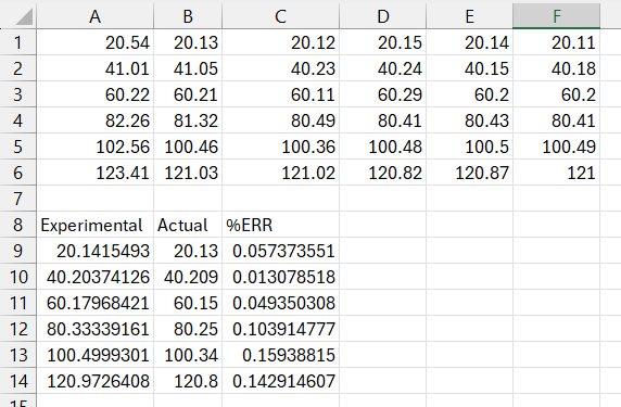
To obtain the data in the table above, the Arduino was set to sample voltage every 100 ms for a minute over several voltage levels (20 VAC to 120 VAC in 20 VAC increments). These samples are in rows 1 – 6 and their average is in the “Actual” column. The experimental values shown in the “Experimental” column were measured and averaged during the same time interval using a calibrated Fluke Multimeter. The Arduino sketch used to obtain this data and the full spreadsheet are included in the OSF respository.
Sponsors/Acknowledgements
This project is currently not sponsored, but if you’d like to support us and become a sponsor, please visit the “Interested in Becoming a Sponsor?” page to learn how!
References
Additional Reading / Resources
Arduino Programming
- Arduino IDE is great for users that are already familiar with it. It also has a very helpful serial plotter in addition to its serial monitor.
- VSCode with the official Arduino Extension allows you to use all of your favorite debugging tools in VSCode and do everything the Arduino IDE lets you do. This is highly recommended for editing code as it allows you to use extensions or tools that you are already familiar with. To add this extension, open VSCode and open the extensions tab. Search for the Arduino Extension and click on “install”. It is also available at this link: https://marketplace.visualstudio.com/items?itemName=vsciot-vscode.vscode-arduino
Hardware
| Description | Link |
|---|---|
| ACS37800 Datasheet | https://www.allegromicro.com/-/media/files/datasheets/acs37800-datasheet.ashx |
| Application Note 296180 | https://www.allegromicro.com/-/media/files/application-notes/an296180-convenient-and-isolated-power-measurements-via-spi-or-i2c.pdf?sc_lang=en |
| Arduino IDE | https://support.arduino.cc/hc/en-us/articles/360019833020-Download-and-install-Arduino-IDE |
| VSCode | https://code.visualstudio.com/ |
| Arduino Extension | https://marketplace.visualstudio.com/items?itemName=vsciot-vscode.vscode-arduino |
| Arduino Nano ESP32 Datasheet | https://docs.arduino.cc/resources/datasheets/ABX00083-datasheet.pdf |
| Arduino Nano ESP32 Cheat Sheet | https://docs.arduino.cc/tutorials/nano-esp32/cheat-sheet/ |
| KiCAD PCB File Generation Guide | https://jlcpcb.com/help/article/16-How-to-generate-Gerber-and-Drill-files-in-KiCad-6 |
Server
| Description | Links |
|---|---|
| Ubuntu installation pages, you can choose the server edition if you do not want a GUI on the system you use as a server. Also, a MakeUseOf article explaining the difference. | https://ubuntu.com/download/desktop https://ubuntu.com/download/server https://www.makeuseof.com/tag/difference-ubuntu-desktop-ubuntu-server/ |
| Rufus is a tool that can help make a bootable USB for installing a Linux distribution of your choice. | https://rufus.ie |
| DigitalOcean is a great resource for setting up a self-hosted environment. Linked is an article for setting up a LEMP stack on Ubuntu 22.04 LTS. | https://www.digitalocean.com/community/tutorials/how-to-install-linux-nginx-mysql-php-lemp-stack-on-ubuntu-22-04 |
| The PHP Documentation is an important resource for understanding the PHP code used in this project and has nearly everything about the language covered in detail. | https://www.php.net/manual/en/index.php |