
Description
BREAD or Broadly Reconfigurable and Expandable Automation Device is an open-source platform that can be configured and used for various applications by creating or combing slices. Each slice has been designed with a specific purpose in mind and new slices can be designed following the BREAD standards to expand capabilities and functionality of the overall system.
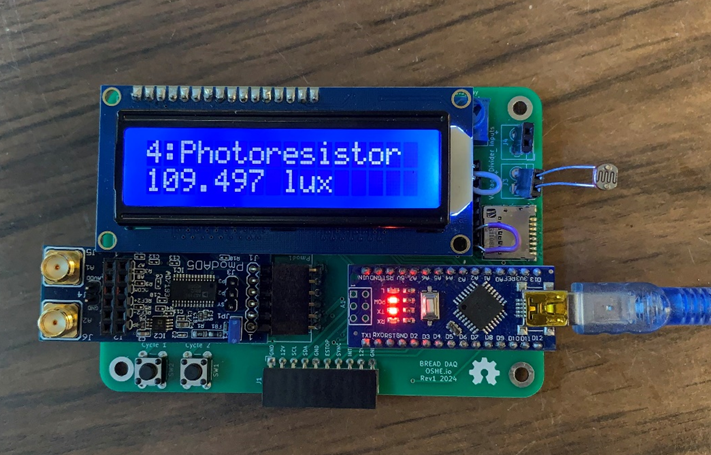
BREAD DAQ is a new slice whose purpose is to log and display data from various sensors. The data is both displayed to an onscreen LCD for real-time viewing and stored to an SD card for historical logging. BREAD DAQ is designed to be generic so that any small signal or resistive sensor can be used with it. DAQ was also designed so that logs can be uploaded to an SQL server for data analysis and mass storage/ archiving.
All files are available for download and modification at the OSF repository, https://osf.io/wxt3s/.
Methodology
The concept for BREAD DAQ is loosely based on an NI DAQ, which has multiple terminals and channels for different devices [1]. The goal is to create different channels that read a type of sensor, for example one with a voltage output, which can then be programmed to interpret the input in different ways and output useful data. The focus currently is on small signal voltage and resistive sensors, specifically thermocouples and photoresistors the process for reading a resistive sensor is simple, as it only needs a voltage divider circuit that can then be read by the Arduino’s built in Analog-to-Digital Converter.
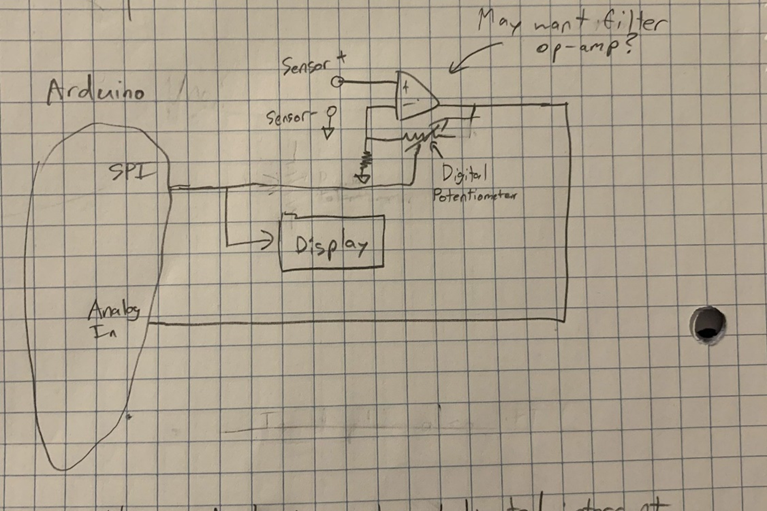
For small signal voltage sensors, some projects were looked at that used an Arduino to read thermocouples. These projects typically used a pre-built amplifier chip such as the AD595 to increase the output of the thermocouple. This increased voltage would then be read by the Arduino’s built-in ADC [2]. The issue with these chips is that they are specific to the thermocouple being used, in this case a K-type thermocouple, meaning that other thermocouple types or non-thermocouple sensors could not be used. Since the project goal was to keep the DAQ as general as possible, it was initially decided to use this concept but using an op-amp to amplify the voltage. A digital potentiometer would then be used to control the gain of the op-amp, as seen in Figure 2. This would allow different small-signal voltages to be used in the same channel.
Unfortunately, this concept did not work. In testing with the op-amp the amplification would be much higher than expected. When set up for 181 V/V and a 10-mV input, the amplification would instead be about 500 V/V. Changing the input to 5 mV would then cause the amplification to be about 700 V/V. This issue may have been caused by op-amp imperfections, however the chip we selected, the MCP6242-E/P did not have terminals to correct for these imperfections. Furthermore, this circuit failed to provide cold junction compensation for the thermocouple, which increases the accuracy of the thermocouple by measuring the temperature of the reference junction and determining the temperature at the hot end by calculating the difference [3]. These failures meant that a new method needed to be found.
An alternative way to read small signal voltages was found in Delta-Sigma Analog-to-Digital Converters. These ADCs use oversampling to perform more comparisons per cycle and adjust the output based on those comparisons [4]. This type of ADC allows the thermocouple to be read directly without amplification, meaning that it can be generalized to read any small signal voltage sensor. An AD7193 chip was chosen for this project as it has cold junction compensation in the form of an on-chip temperature sensor that the thermocouple sensor is added to. There is also an Arduino library already made that can be used to read from the chip [5]. Specifically, the pre-built PmodAD5 board was used for easy interfacing with the Arduino.
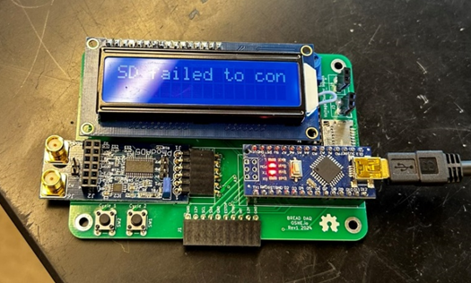
This setup is not useful unless the data can be read and logged. BREAD DAQ does this by displaying data to an LCD screen in real time while logging each reading to an SD card. This allows the data to be used in future analyses while also giving real-time feedback should adjustments need to be made immediately. To make this stored data useful, a timestamp associated with each data point is needed. Since the Arduino Nano being used can only track time since the current program has started, which will be reset if power is lost, a real time clock (RTC) was added to provide this timestamp. A coin cell battery was also added to provide power to the RTC when main power is lost so that the stored time is maintained. The RTC communicates with the Arduino using I2C.
Writing to an SD card poses a few difficulties as well. The primary issue is that the SD requires 3.3V logic levels and power, however the Arduino operates at 5V. A logic buffer and 5V to 3.3V regulator were added to address this issue. Arduino can interface with SD using SPI, this allows for the data to be stored in a text file. To make analysis easier, the text file is formatted as spaced columns such that a python script can easily translate and store the data to an SQL database. This allows for all log files to be combined into a query-able, centralized, and easily expandable location.
Bill of Materials
| Description | Part Number | Source | Unit Price | Qty | Cost |
| Thermocouple | 240-080 | Digi key | $9.99 | 1 | $9.99 |
| Liquid Crystal Display | 398 | Digi key | $17.95 | 1 | $17.95 |
| Real Time Clock Module | PCF8523T/1,118 | Digi key | $1.34 | 1 | $1.34 |
| Battery Tray[JK4] [BH5] | BC2032-E2 | Digi key | $1.02 | 1 | $1.02 |
| Battery | P189-ND | Digi key | $0.41 | 1 | $0.41 |
| 32.7680 kHz Crystal Oscillator | AB38T-32.768KHZ | Digi key | $0.18 | 1 | $0.18 |
| Push Button | TS02-66-55-BK-100-LCR-D | Digi key | $0.10 | 2 | $0.20 |
| SD tray | 1040310811 | Digi key | $2.24 | 1 | $2.24 |
| Terminal | EB21A-02-D | Digi key | $0.75 | 2 | $1.50 |
| 10µF Capacitor | CL31B106KOHNNWE | Digi key | $0.17 | 2 | $0.34 |
| 10kΩ Resistor | RC1206FR-0710KL | Digi key | $0.10 | 4 | $0.40 |
| 20kΩ Resistor | ERA-8AEB203V | Digi key | $0.39 | 2 | $0.78 |
| 50kΩ Resistor | RT1206BRD0750KL | Digi key | $0.33 | 2 | $0.66 |
| 100kΩ Resistor | RC1206FR-07100KL | Digi key | $0.10 | 2 | $0.20 |
| 1MΩ Resistor | ERJ-8ENF1004V | Digi key | $0.18 | 2 | $0.36 |
| Jumper | SSC02SYAN | Digi key | $0.21 | 2 | $0.42 |
| Photoresistor | 161 | Digi key | $0.95 | 1 | $0.95 |
| 10kΩ Potentiometer | 356 | Digi key | $1.25 | 1 | $1.25 |
| 1×6 Horizontal Header | PPPC061LGBN-RC | Digi key | $0.67 | 1 | $0.67 |
| 1×10 Horizontal Header | PPPC101LGBN-RC | Digi key | $0.79 | 1 | $0.79 |
| 1×15 Socket Header | PPPC151LFBN-RC | Digi key | $1.03 | 2 | $2.06 |
| 1×16 Socket Header | PPPC161LFBN-RC | Digi key | $1.03 | 1 | $1.03 |
| 1×16 Connection Header | PH1-16-UA | Digi key | $0.27 | 1 | $0.27 |
| Voltage Regulator | LP5951MFX-3.3/NOPB | Digi key | $0.75 | 2 | $1.50 |
| PmodAD5 (AD7193 Breakout) | 410-243 | Digi key | $34.00 | 1 | $34.00 |
| Buffer | CD74HC4050E | Digi key | $0.62 | 1 | $0.62 |
| PCB Boards (x5) | JLCPCB | $21.59 | 1 | $21.59 | |
| Total | $102.92 |
Tools Used
| Category | Item | Part Number | Source | Cost |
| Testing and Planning | Breadboard | ZYJ-102 | Adafruit | $5.95 |
| Multimeter | Fluke 179 | Fluke | $479.99 | |
| Oscilloscope | MSO6012A | Test Equity | $2955.00 | |
| Heat Gun | 8977-20 | Milwaukee Tool | $210.09 | |
| Temperature Sensor | T400 | Adafruit | $175.00 | |
| Assembly | Solder Iron | FX-888D | Hakko | $121.47 |
| KiCAD Schematic Capture and PCB Editor | KiCAD 8.0.1 | KiCAD | $0 | |
| Programming | Arduino IDE | Arduino IDE 2.3.2 | Arduino | $0 |
Assembly Instructions
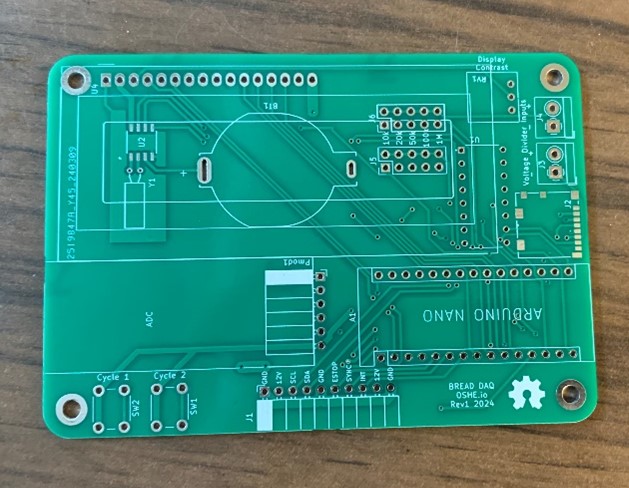
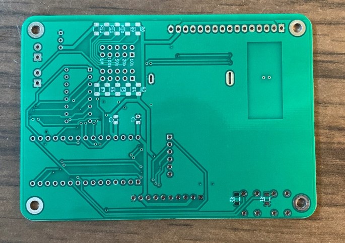
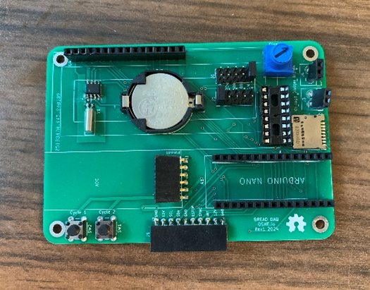
All parts can be ordered from Digi-key using the hyperlinks in the BOM aside from the PCB. The PCB can be ordered from JLCPCB using the Gerber files provided in the OSF Repository. The components can be soldered to the PCB according to the PCB KiCAD file in the OSF Repository. It’s recommended to solder surface mount components first such as the RTC, SD tray, Resistors, and Capacitors. Then solder through-hole components.
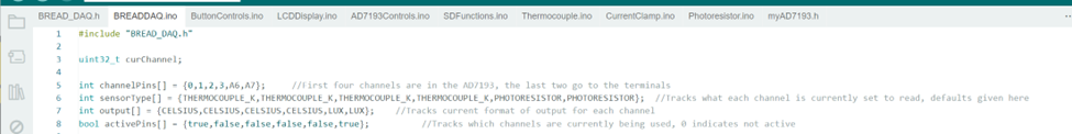
After the board has been assembled, download the code from the OSF repository. Some setup will need to be done depending on the application desired and which channels are being used. As seen in Figure 6, there are global arrays used to hold which pin/terminal is used for each channel. The channelPins array can be rearranged to map which channel number goes to each pin or changed if the PCB is modified. The sensor Type and output arrays should be changed to change the default settings for each channel, although the type of sensor can be changed in real time using the push buttons. Finally, the activePins array needs to be set for which channels are being used. Only channels with a true will be read and written to the SD card.
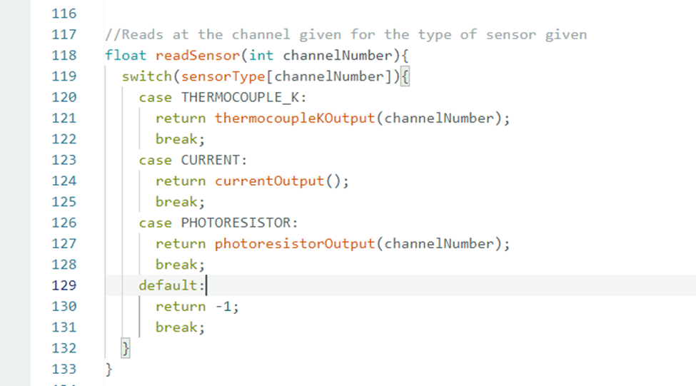
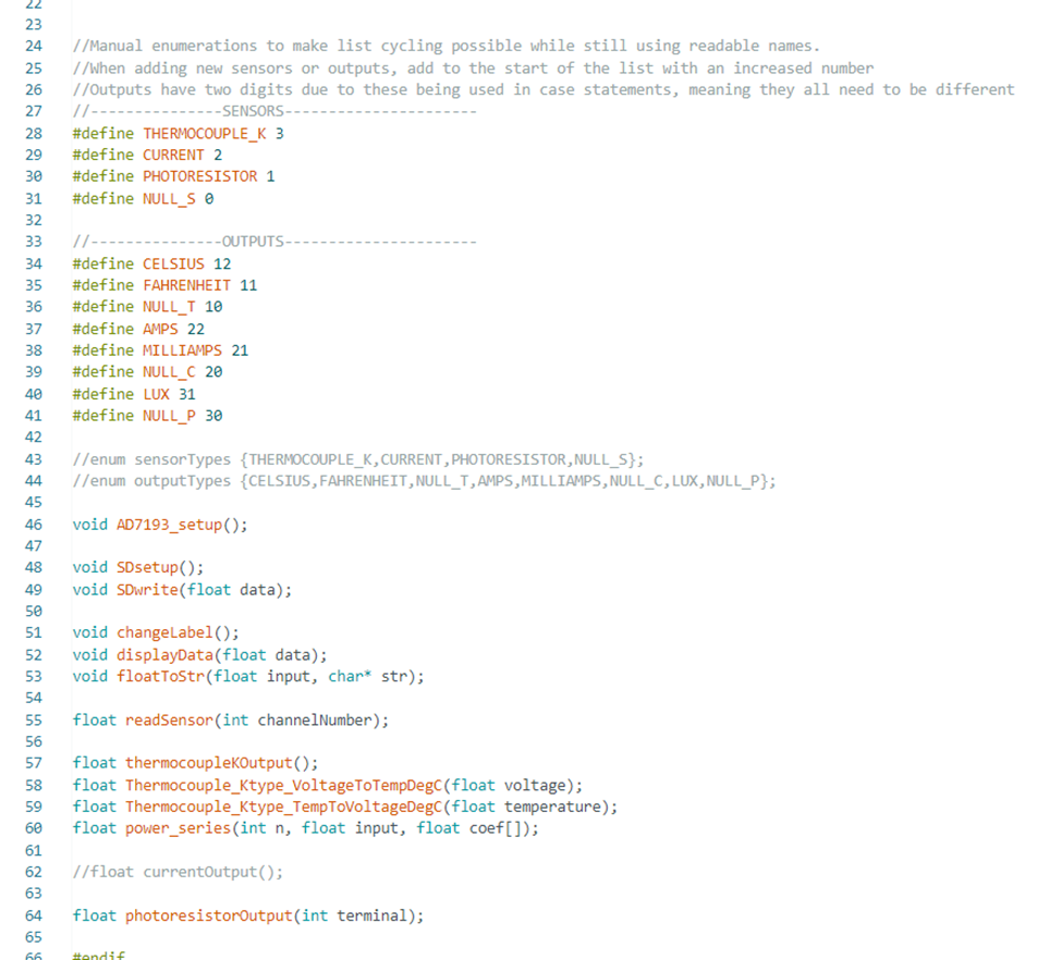
To add a new sensor, write the conversion code desired. Then, update the switch case in the readSensor function in BREADDAQ.ino to use the new conversion code when set for the proper sensor, as seen in Figure 7. To do this properly, a new sensor and possibly units will need to be added to the manual enumeration in the header file, BREAD_DAQ.h, as seen in Figure 8. The conversion code can also be declared in this header file.
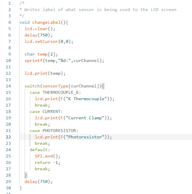
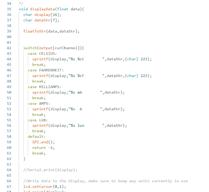
The LCDDisplay.ino file will also need to be updated to print to the LCD screen properly. The changeLabel function will need a new case to display the sensor being read properly. The label being written should be 14 characters or less and it is recommended to use the F() macro to save space. If the sensor uses a different unit than any programmed units, the displayData function will also need to be modified to output correctly when that output is selected.
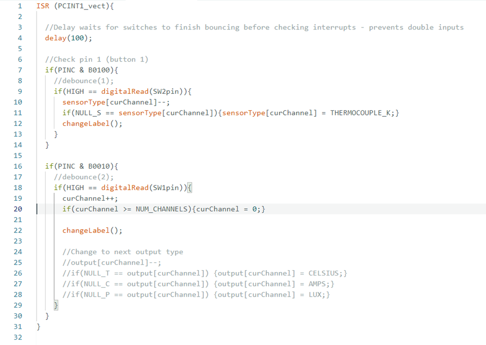
Finally, ButtonControls.ino will need to be edited if THERMOCOUPLE_K is no longer the largest enumeration. The only thing should be to make the largest sensor enumeration the one that is reset to when SW1 is pressed. Also, to instead cycle the output units the commented-out code can be used in place of one of the interrupts.
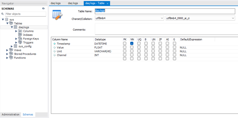
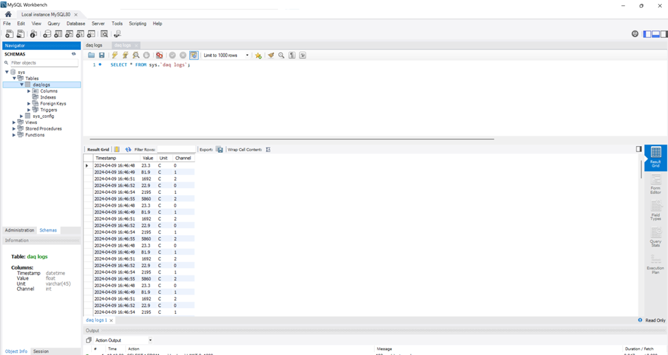
The process for setting up a SQL server is straightforward. The code is designed to connect to a MySQL server. To connect to an existing server, first create a table for the logs to be stored in with 4 columns. Then change the address in the python file to the address of the server and add appropriate credentials (ensure the credentials being used have write access to the appropriate table). Finally, ensure that the table name in the script matches the table name in the server. Creating a new server can be done by downloading the MySQL installer and following the prompts.
To upload the logs to the server simply move the log files from the SD card and onto a PC and place the python script in the same folder. Modify the code by entering the IP, database name, table name, username, and password. Once all files are in the same folder as the python script and the proper parameters for the server are set, run the python script and the logs will be translated to the server automagically.
Characterization Data
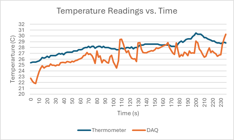
To test the board, a heat gun was used to warm the DAQ’s thermocouple and a temperature sensor. These values were then compared over time. This attempt to characterize the temperature reading shows a high level of error (~5%). Although the DAQ follows temperature it may not be as accurate as other temperature sensors. It is also possible that the testing method is flawed, as the equipment used did not guarantee a temperature-controlled environment. Much more testing would need to be done to find exactly what the error is and how to correct it.
Acknowledgements
Thanks to Anne Mahaffey for creating an Arduino library for the AD7193 and a Thermocouple conversion code.
References
| [1] | National Instruments, “Data Acquisition (DAQ),” [Online]. Available: https://www.ni.com/en/shop/data-acquisition.html. [Accessed 22 January 2024]. |
| [2] | Electronic Wings, “Thermocouple Interfacing With Arduino UNO,” [Online]. Available: https://www.electronicwings.com/arduino/thermocouple-interfacing-with-arduino-uno. [Accessed 22 January 2024]. |
| [3] | Omega, “Cold Junction Compensation for Thermocouples,” [Online]. Available: https://www.omega.com/en-us/resources/thermocouple-junction-principles. [Accessed 16 February 2024]. |
| [4] | All About Circuits, “Delta-Sigma ADC,” [Online]. Available: https://www.allaboutcircuits.com/textbook/digital/chpt-13/delta-sigma-adc/. [Accessed 29 February 2024]. |
| [5] | ADI Engineer Zone, “AD7193 + Arduino Tutorial – Thermocouple Measurements,” [Online]. Available: https://ez.analog.com/data_converters/precision_adcs/w/documents/2849/ad7193-arduino-tutorial—thermocouple-measurements. [Accessed 29 February 2024]. |