
prepared by: Xavier Haupt, Konnor Kuppernus, James Lovell, William Forney
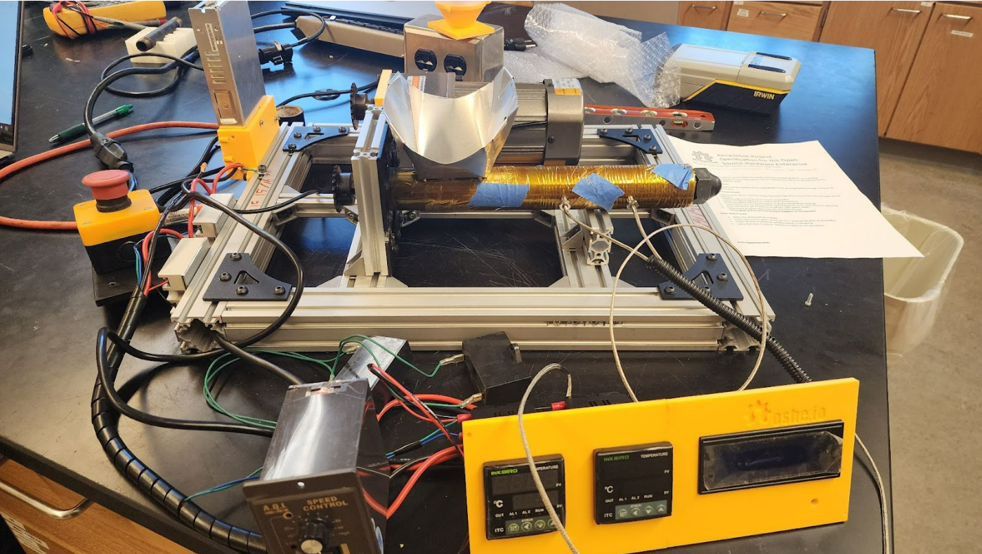
Figure 1. Image of RecycleBot 4/25/24
Quick Links
Project Description Writing
RecycleBot is a project aimed at helping smaller scale 3D printer users to cut down on costs and waste material. In melting down old 3D printer filament and mixing in a percentage of new material to maintain standards of material properties, waste can be reduced and users can avoid buying new filament. Recycle-bot is a modular design, multi semester project. The proposed modules include extruder module, where plastic is melted, mixed, and squeezed out in a stream of filament before being passed to the next module. The cooling module receives the melted stream of new filament and passes it along while bringing the filament to a stable temperature. The rewind module will measure the diameter of the incoming filament to insure quality standards while winding the new filament around an empty spool for future use.
This semester the Recycle-bot team focused on the extruder module. The stresses and loads created by mixing plastic necessitated a frame redesign, replacing wood for aluminum tubing. Moving the motor from direct drive to an offset chain drive created a safer system and allowed a more compact design. The larger newer extrusion barrel called for a rework of the heating system using 2 inkbird temperature controllers to control two heating zones to monitor the mixing process.
Methodology Writing
The current version for RecycleBot was spurred by the critical failures of the previous version. In the previous model various issues culminated into a total failure of the unit. Some of these being, a limited form factor from the 2×6 board it was mounted to, plastic parts attached to heated zones, the barrel and motor were not reinforced enough to handle more difficult polymers, limited heating zones, and the limited size of the barrel and screw.
The learning gained from the previous version of RecycleBot were combined with market research into what options are currently available on the market. Various models were researched to determine what options and methods were being employed for consumer use. Combining this research with the learning from the previous RecycleBot were combined to identify key changes.
Aluminum Frame
The first key change was to use 80/20 aluminum extrusion to mount all the components like motors and extrusion barrels. Not only does it have a much stronger frame than before but it also provides adaptable mounting. The new frame will be able to handle much stronger forces involved with extrusion. The adaptable mounting will also allow for adjustable motor and barrel mounts. Now the unit does not need a specific screw or motor. The mounts can be adjusted for different combinations of motor and screws to work on the same unit. While this would involve adjusting or redesigning certain components used to attach each unit to the frame mounts, it still allows for a much more flexible design. The aluminum frame also allows for the removal of a majority of 3d printed / plastic parts. While these parts are often easier to manufacture, they often cannot handle the forces or heat involved in extrusion. By changing the core of the mounting system we can eliminate these issues and create a more robust unit.
Chain Drive
The next key change was switching to a sprocket and chain drive train for the motor to extrusion screw. This eliminates the issue of using 3d printed parts to engage the motor to the screw. In the previous version of RecycleBot the 3d printed adapter between the screw and motor broke during extrusion causing a lot of the damage to the unit. By switching the chain and sprocket set up it leads to a much stronger connection. This also allows for more adaptive mounting to follow in suit with the idea of the frame mounting. Now the drive can use any motor screw combination as long as the chain still has clearance. The chain drive can also have different gear ratios used to take advantage of the additional torque in the motor. The sprockets can be changed out to increase or reduce the RPMs of the extrusion screw. This allows us to optimize the load and throughput of the unit
Multiple Heating Zones
Multiple heating zones are used by many consumers, and are present on most of the polymer extruders present in the industry today. By adding a second temperature zone with separate controls it allows for more precise melt control. It allows for proper control of the melt zones creating a preheating and melt section, this will improve the efficiency and throughput of the unit. Preheating improves the throughput of the unit by preventing premature melt of the flow. If the flow melts or is not viscous too early the polymer will slip around the barrel rather than progress forward. This causes a loss in pressure and throughput during the process.
Extrusion Screw
The previous version of RecycleBot used a combination of a metal pipe and auger bit to push the melt flow. While this did work, it made controlling, material changeover, and heating difficult. The decision was made to move to a purpose built extrusion screw and barrel to improve the quality of the unit. Extrusion screws have very specific zones in the screws to control the flow of the polymer during processing. By switching to an extrusion screw it will improve flow, control of flow, heating, material changeover, and consistency of the product. This is mostly achieved from the flighting of the screws. Flighting is the change of angle, depth, volume between the screws. Generally, as the screw approaches the nozzle of the unit it gets thinner, or the distance between the screw channel and wall of the barrel is reduced. This means there is less material near the front of the barrel. Material moves faster as it approaches the nozzle to keep the volumetric flow rate. This assists with start-up as there is less material to drive heat into and helps with mixing and even flow rate as it approaches the nozzle.
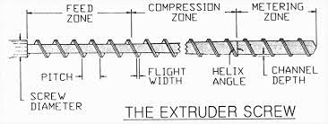
Figure 2. Diagram of Extrusion Screw Zones
Bill of Materials
| Part | Part number (where applicable) | Amount required. |
|---|---|---|
| Jugetek Extrusion Barrel and screw (16mmx305mm) | 1 | |
| Ink Bird temperature control unit | SSR-25DA ITC-100VH | 2 |
| OCR corner brackets | ~40 | |
| Thrust Bearing | Generic found in shop | |
| Kapton Tape | ½’’ tape roll | 1 roll |
| Nichrome Wire | 31 AWG | 100 feet / 1 roll |
| Thermocouple | K-type M6 thread | 2 |
| 15 MM Sprocket 20 Tooth | A21121100ux0344 | 1 |
| 15 MM Sprocket 24 Tooth | A21121100ux0388 | 1 |
| 14 MM Sprocket 20 Tooth | a21121100ux0343 | 1 |
| 25 Chain | Uxcell #25/04c-1 | 10 feet |
| 40mmx40mm Aluminum Extrusion – 72″ | 72” | |
| 20mmx40mm Aluminum Extrusion – 36″ | 36” | |
| 20mmx20mm Aluminum Extrusion -24″ | 24” | |
| L Brackets | XC5299-10 | 10 |
| M5 Washers | a15071400ux0047 uxcell | |
| M5 Bolts – 12mm long | a15071800ux0189 uxcell | |
| M5 Channel Nuts | BR-TN-0015 | |
| Power Supply | ||
| AC Gearmotor |
Tools Used:
- 3D printer (Prusa Mk4 used, but any printer with a build volume of at least 225mm-90mm-96mm will work)
- Drill
- Hacksaw (bandsaw probably works better)
- Allen wrench
- Wire cutters
- Aviation tin snips
- Dremel
- Vice
- Files of various sizes
- Pliers
- Wire Crimpers
- Wire Strippers
Assembly Instructions
- Aluminum Base Frame
- Step one cut all pieces to size
- Piece should be cut and fit together from the outside in, please follow the following diagram
- A hacksaw was used for most cuts, but any tool with metal cutting capabilities could be used
- All mounts and brackets used standard 20mm aluminum extrusion nuts and internal slide bolts
- All piece should be cut longer than the measurement than filed down for snug fit
- Step one cut all pieces to size
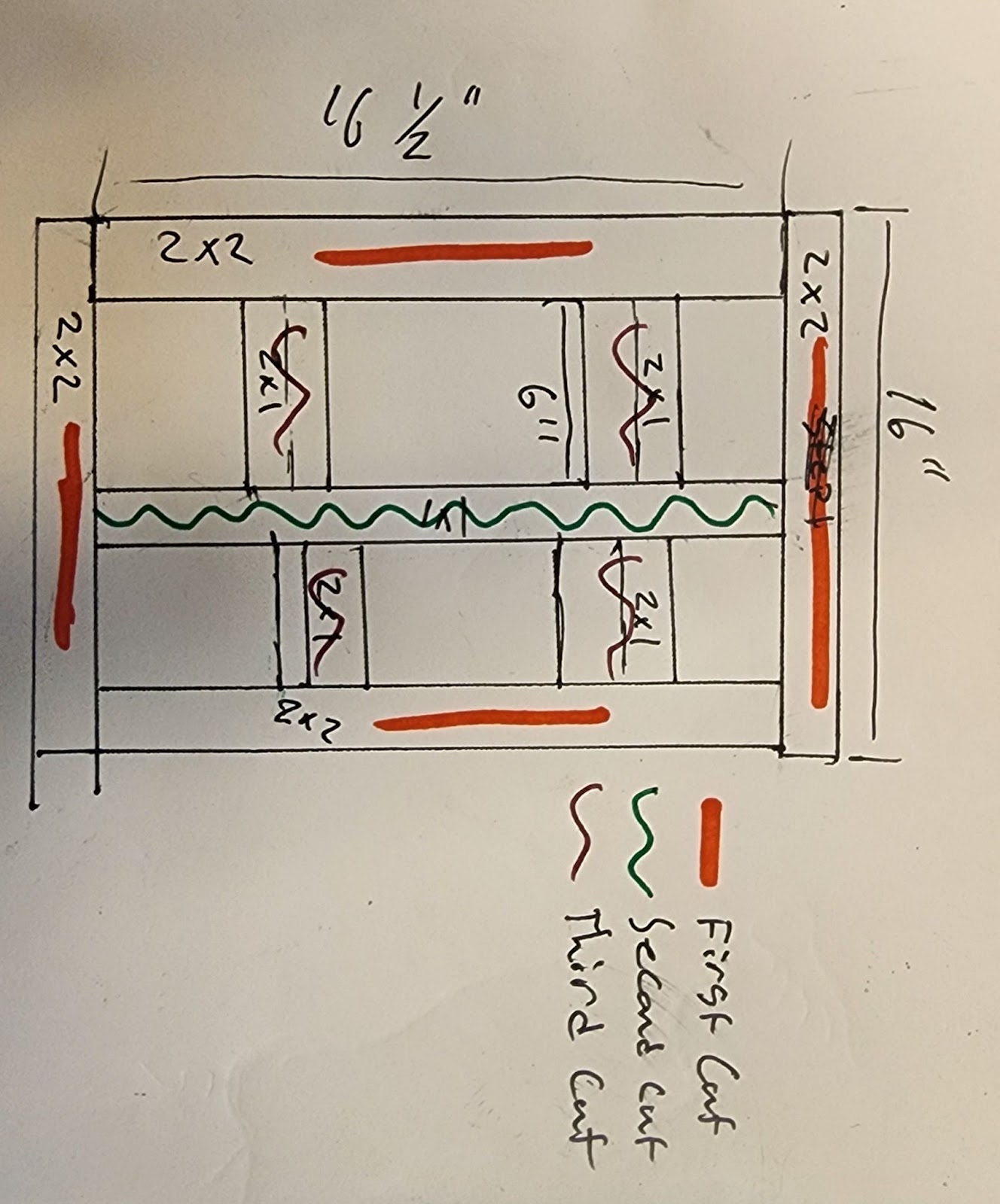
Figure 3. Diagram of Cut Order
- The orange pieces should be cut first a secured with the corner brackets
- Two 16’’ 40mmx40mm Aluminum Extrusion pieces
- Two 16.5’’ 40mmx40mm Aluminum Extrusion pieces
- Seen in figures 4 and 5
- Next the Second Cut should be cut and fit into the unit
- One 16’’ 20mmx20mm Aluminum Extrusion peece
- This will be connect to the side wall of the 40mmx40mm piece with two inside corner brackets on each side, seen in figure 6
- Next Cut the third cut piece and fit them into between the 40mmx40mm wall pieces and the 20mmx20mm inside mount
- Connect the same way the center bar was placed with two inside corner bracket mounts
- Four 6’’ 20mmx40mm pieces
- Seen in figure 7
- The final assembly of the base frame should resemble figure 8
- This frame can now be used with the inside corner brackets and other mounting devices the the frame
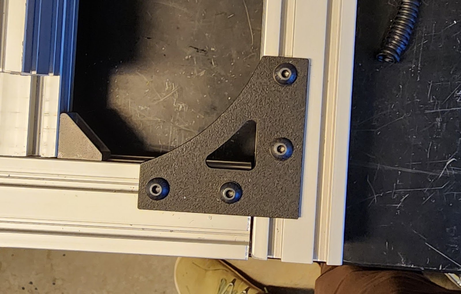
Figure 4: Image of Corner Bracket
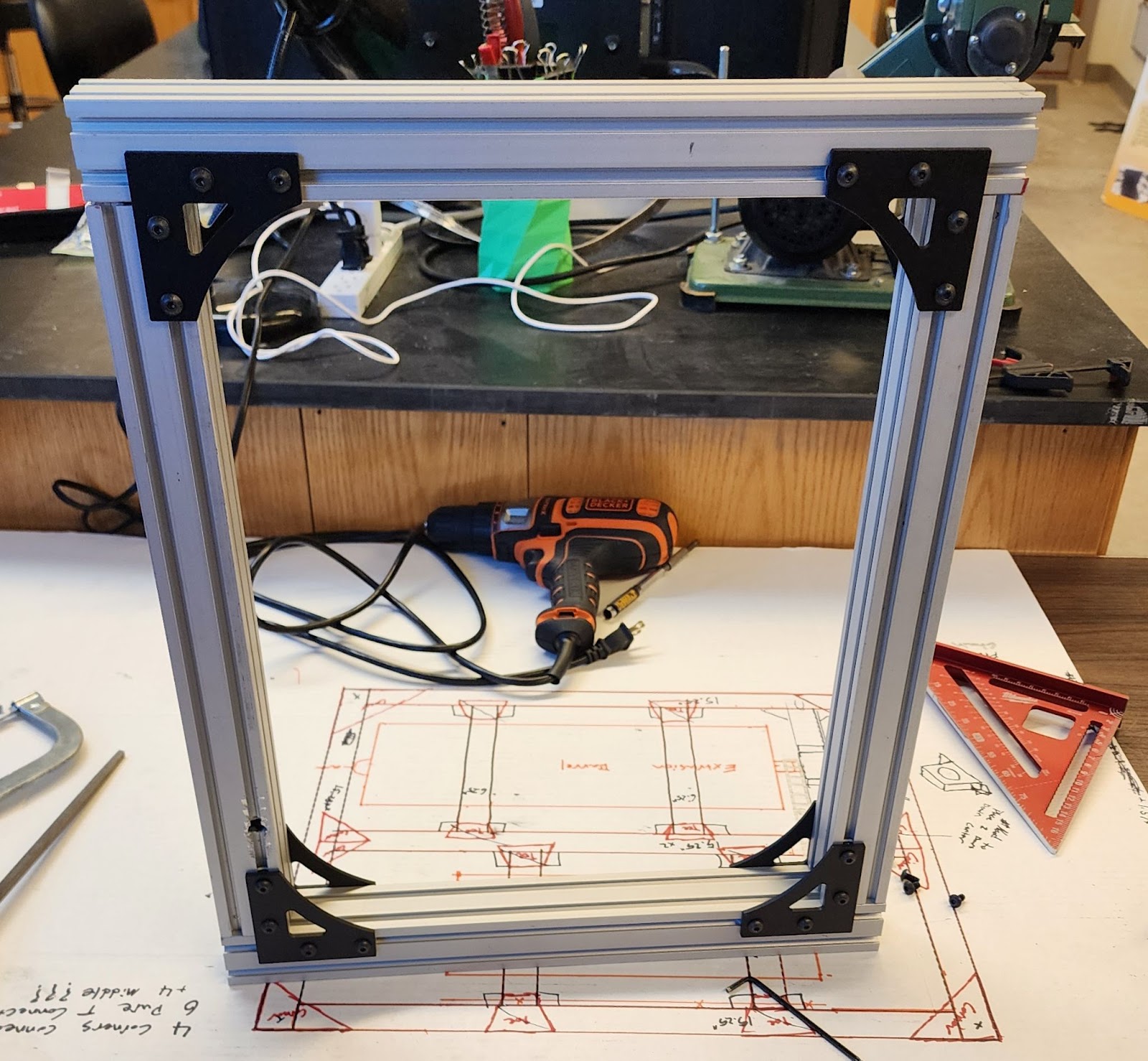
Figure 5: Image of complete step one frame
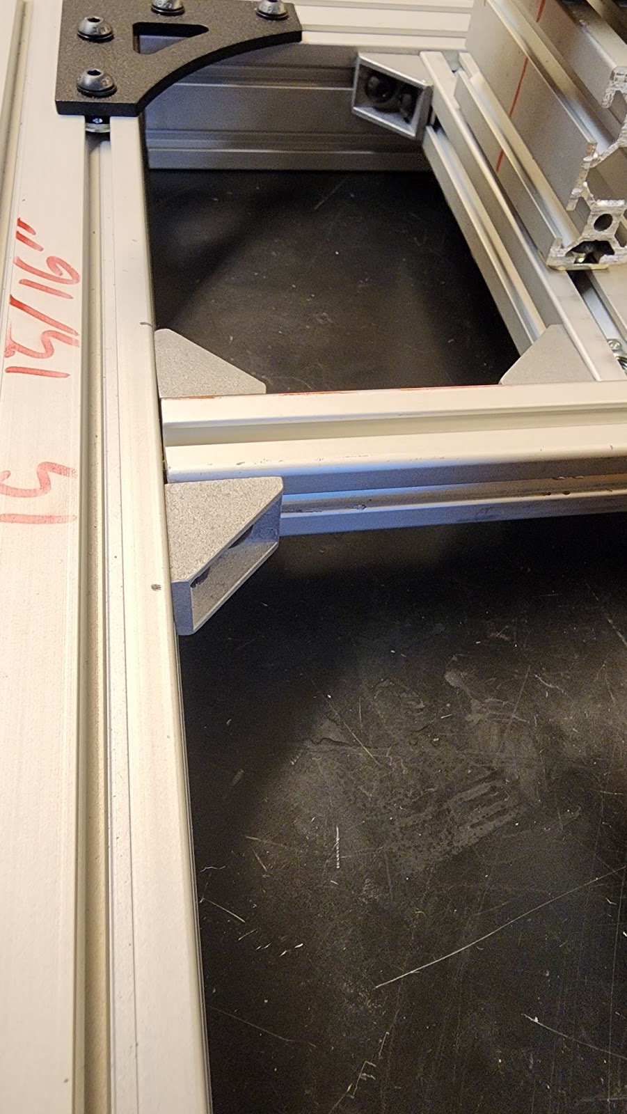
Figure 6: Image of center bar and inside corner brackets
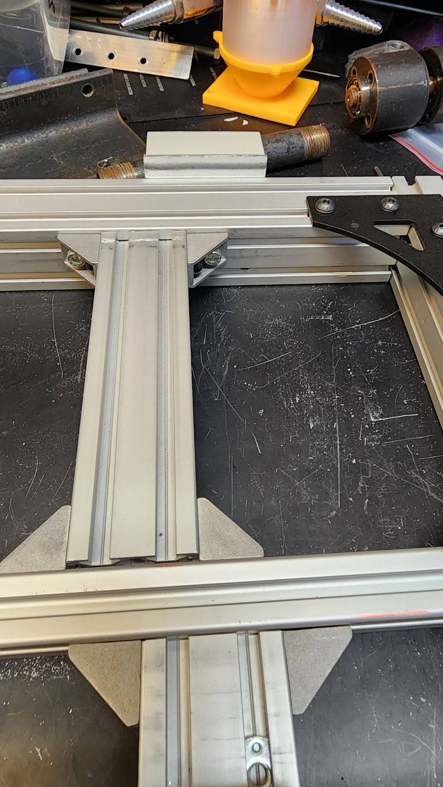
Figure 7: Image of 20mmx40mm internal mounting blocks
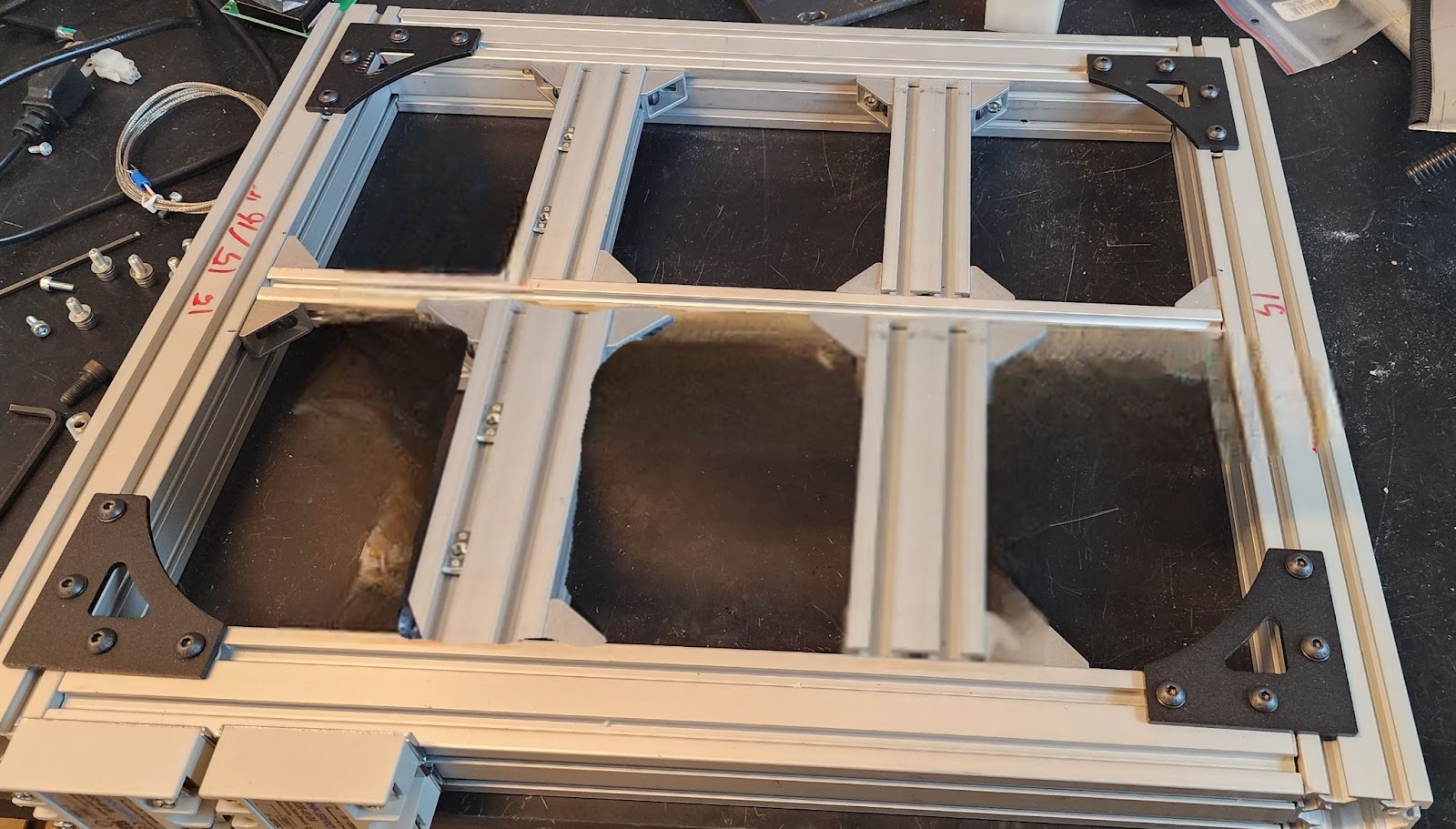
Figure 8: Final Construction of the base frame
- Barrel Mount Construction
- 20mmx20mm Aluminum Extrusion will be used to create a custom mount for the Jugetek barrel
- First cut the following piece out with a hacksaw or other metal cutting device
- Two 4.5’’ 20mmx20mm aluminum extrusion pieces
- Two 3’’ 20mmx20mm aluminum extrusion pieces
- Please ensure fit by cutting extra and filling down for a good fit together
- Next the internal channel will need to be widened to fit the flange of the Jugetek barrel
- The best way to do this is the file down the insides and check for the fit around the flange
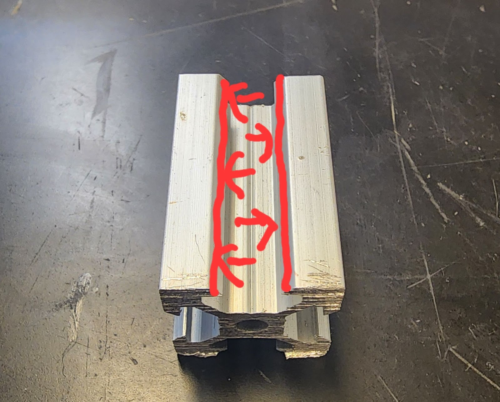
Figure 9: Example of what need to be filed down
- Next the surface L brackets need to be prepared
- This will involve two standard L brackets and two cut down L brackets
- These are the same brackets
- Alternatively one could use two normal L brackets and two small form L brackets
- This need to happen due to size constants on the barrel mount, seen in figure 10
- This will involve two standard L brackets and two cut down L brackets
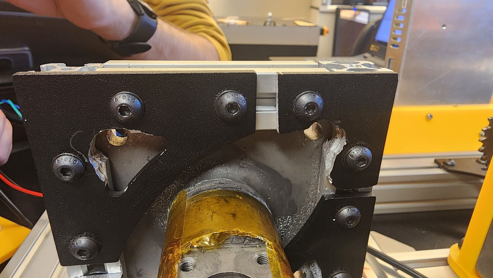
Figure 10: Image of the bracket cut down
- Once the aluminum extrusion channel are widened and the brackets are cut to size, the mount can be built around the flange of the Jugetek barrel
- All mounting was down with standard 20mm aluminum extrusion bolts and internal nuts
- Now inside corner brackets can be used to connect the aluminum extrusion around the flange to one of the crossbars on the frame
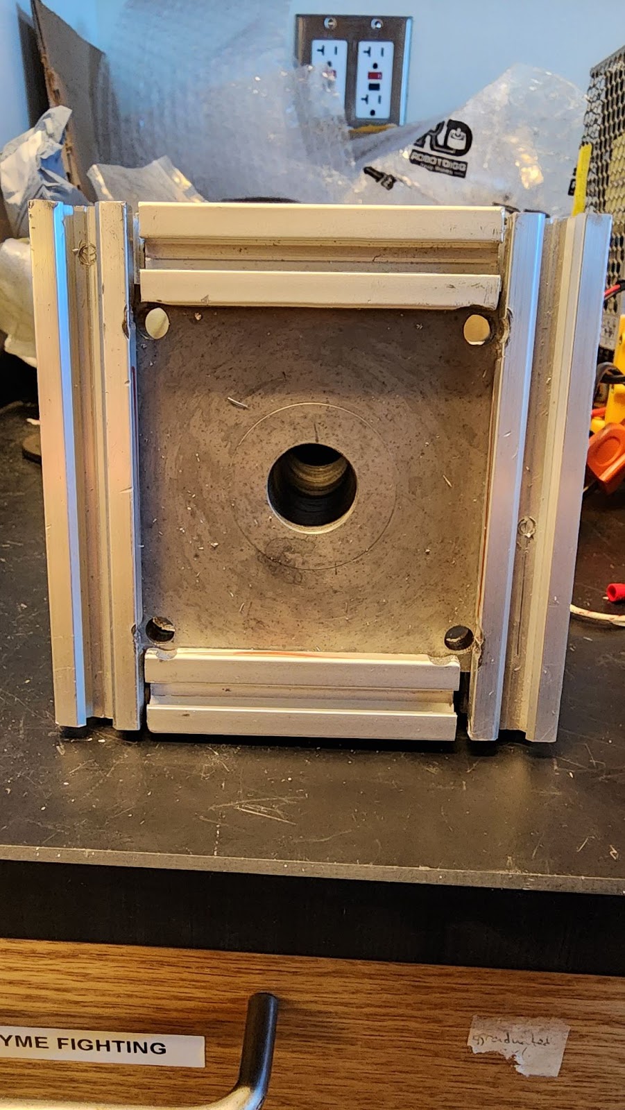
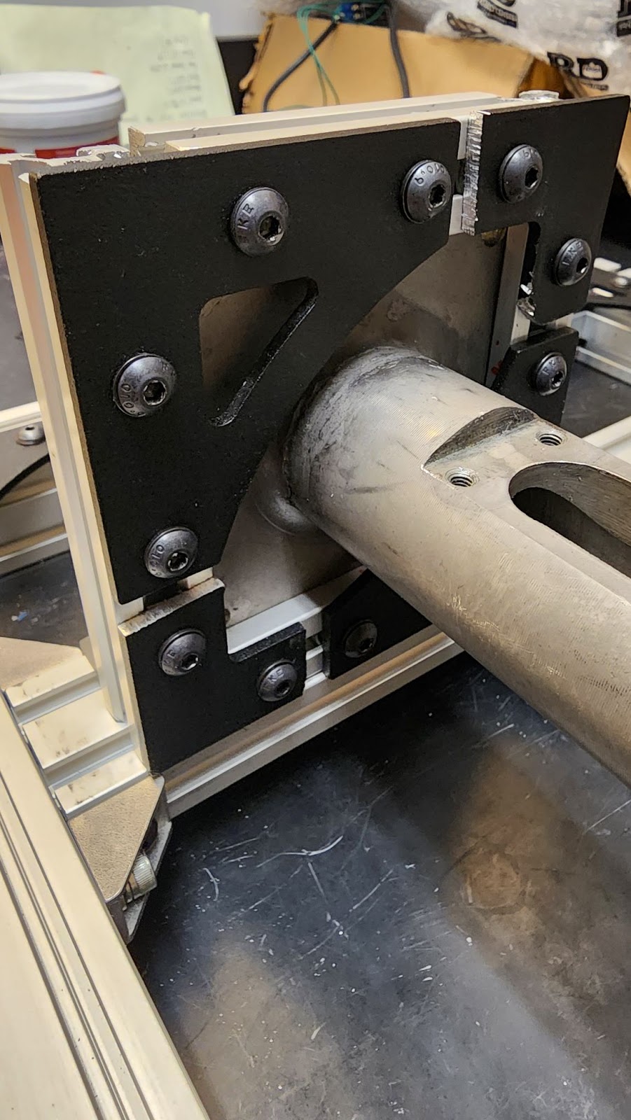
Figure 11: Image of the front and back of the mount built around the Jugetek barrel flange
- A 3’’ long piece of 20mmx40mm will also need to be cut to support the front of the barrel
- This piece will need to have a slight channel carved to fit the barrel, and need to have washer placed between the frame and piece to give a little extra height
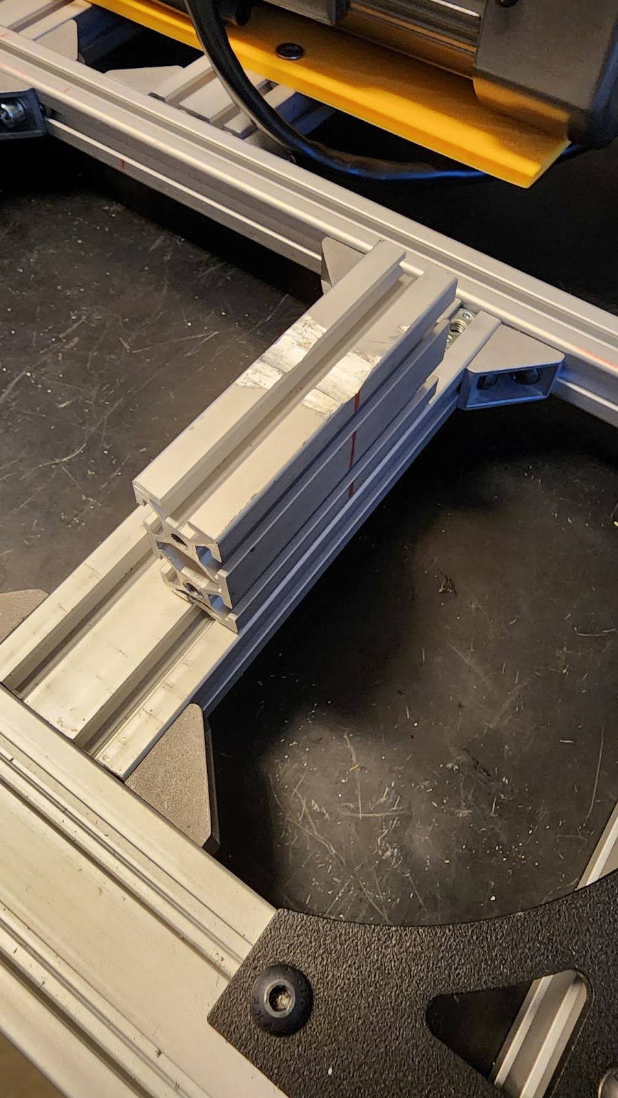
Figure 12: Image of front barrel support
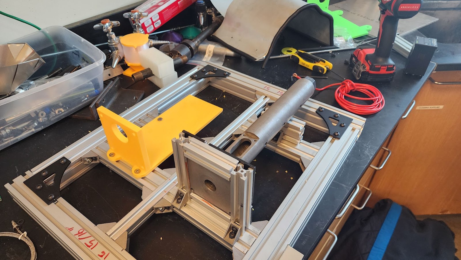
Figure 13: Image of barrel mounted to completed frame
- Motor mount
- Measure and create 3d print to match the motor’s footprint.
- Mount to aluminum frame by aligning frame supports and anchor with M5 screws.
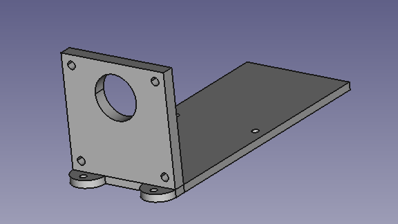
Figure 14: Motor Mount
- Hopper
- Create an 8’’x8’’ paper silhouette and draw out the footprint of the extrusion barrel’s matting surface in the center of the paper.
- Puncture silhouette to mark screw holes and the plastic channel.
- Overlay paper on aluminum sheet, stencil sketch the outline and mark corner cut lines and screw holes on the aluminum.
- Use Tin Snips to cut out an aluminum square. Cut straight lines from the outside corners of the aluminum sheet to the corners of the box in the center.
- Fold Corners into funnel shape and fold over excess materials to remove the edge hazzard and to assist in holding the shape of the funnel.
- Drill out center holes and screw holes to match the mounting screw in the extrusion barrel.
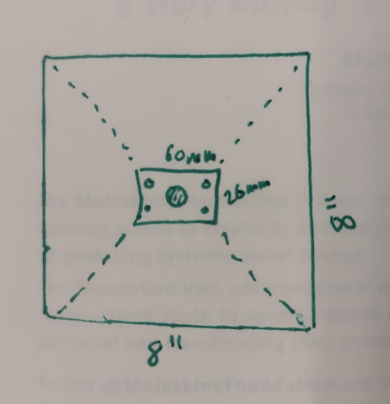
Figure 15: Hopper Cutout Plan
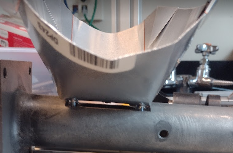
Figure 16: Hopper mounted to extrusion barrel
- Power Supply
- Parts Required, 12V power supply (LRS-150-12), (7) M3 X 10mm Bolt, M5 X 20mm Bolt, (2) M5 channel Nut, Power_Supply_Cover_x1.stl, Power_Supply_Mount_x1.stl,
- Melt (4) heat inserts into the front side of the power supply cover.
- Mount power supply to the cover with (3)M3X10mm bolts in each remaining hole around the cover.
- Connect 6’ 3 prong extension cord into corresponding Line, Neutral, and Ground(⏚) terminals
- Ensure faceplate fits flush against power supply cover and ensure a secure fit.
- Secure to frame using (2) M5 x 20 bolt and (2) M5 channel nut.
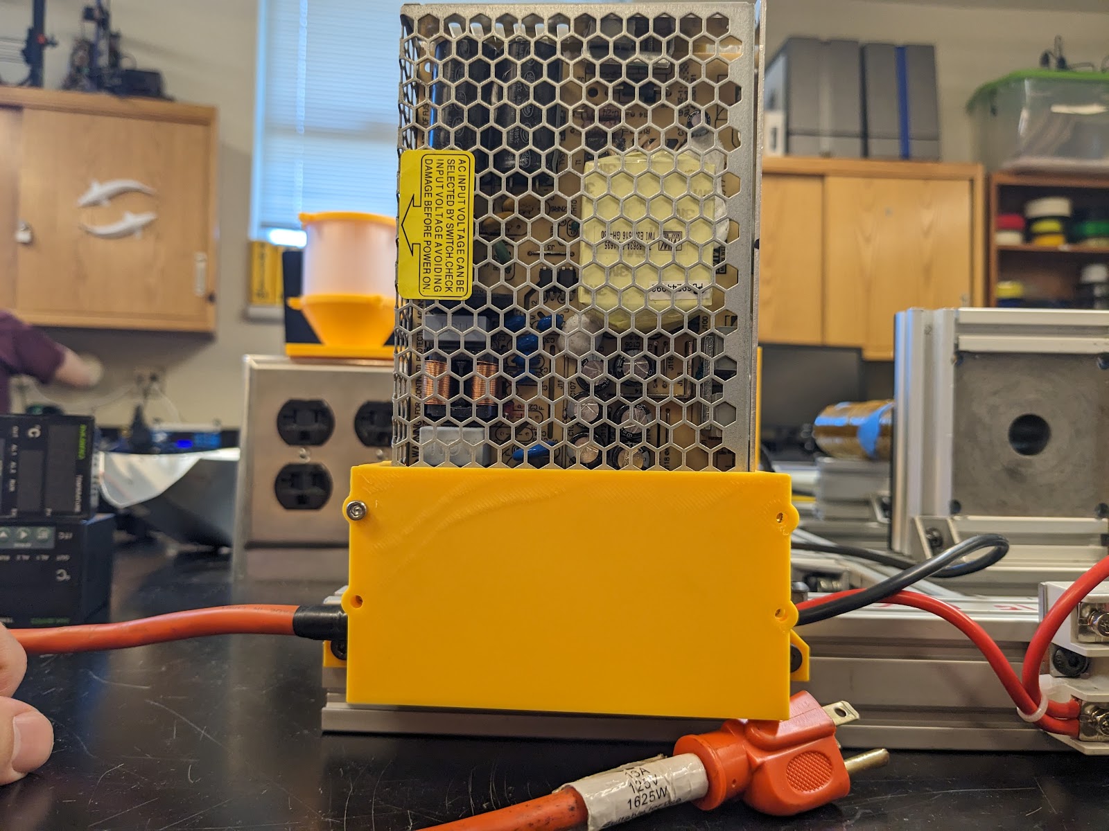
Figure 17: Power Supply Mounted to Frame
- Heater Relays
- Parts Required (2) Ink Bird SSR-40 DA Relay, (4) M5 X 12mm bolt, (4) M5 channel nut
- Widen SRR Relay mounting holes to fit a M5 X 12 bolt
- Mount to frame using (4) M5 X 12mm bolt and (4) Mt channel nuts
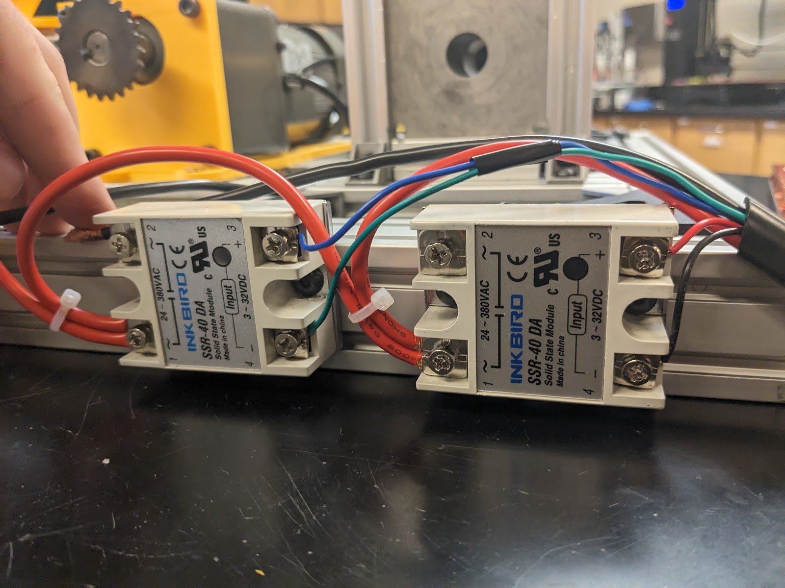
Figure 18: Relays Mounted on Frame
- Wrapping extrusion barrel
- Parts Required Extrusion Barrel, Kapton Tape, Nichrome Wire
- Wrap an entire layer of Kapton Tape around the barrel. Wrap spaced layer of Kapton Tape where the sticky side is facing away from the barrel. This will be used to help seat the nichrome wire.
- Hot Heat Zone: For the first 90mm of the barrel starting from the nozzle wrap a tightly evenly spaced layer (~ 1 mm Spacing) of Nichrome wire. Ensure both ends have 30- 50mm remaining for future wiring. It is important that the wires do not cross.
- Middle and Preheating Zone: For the remaining length of the barrel begin wrapping an evenly spaced layer (~ 1mm Spacing) of Nichrome wire. Once 50mm is remaining before the hopper, begin spacing the Nichrome wrapping to 10mm for the remaining space. Again ensure both ends have 30 – 50mm remaining for future wiring.
- Begin wrapping the final layer of Kapton Tape on top of Nichrome wrapping ensuring no wires cross or touch. It is important that the wires do not cross. Leave both ends of the Nichrome Wire exposed for future wiring.
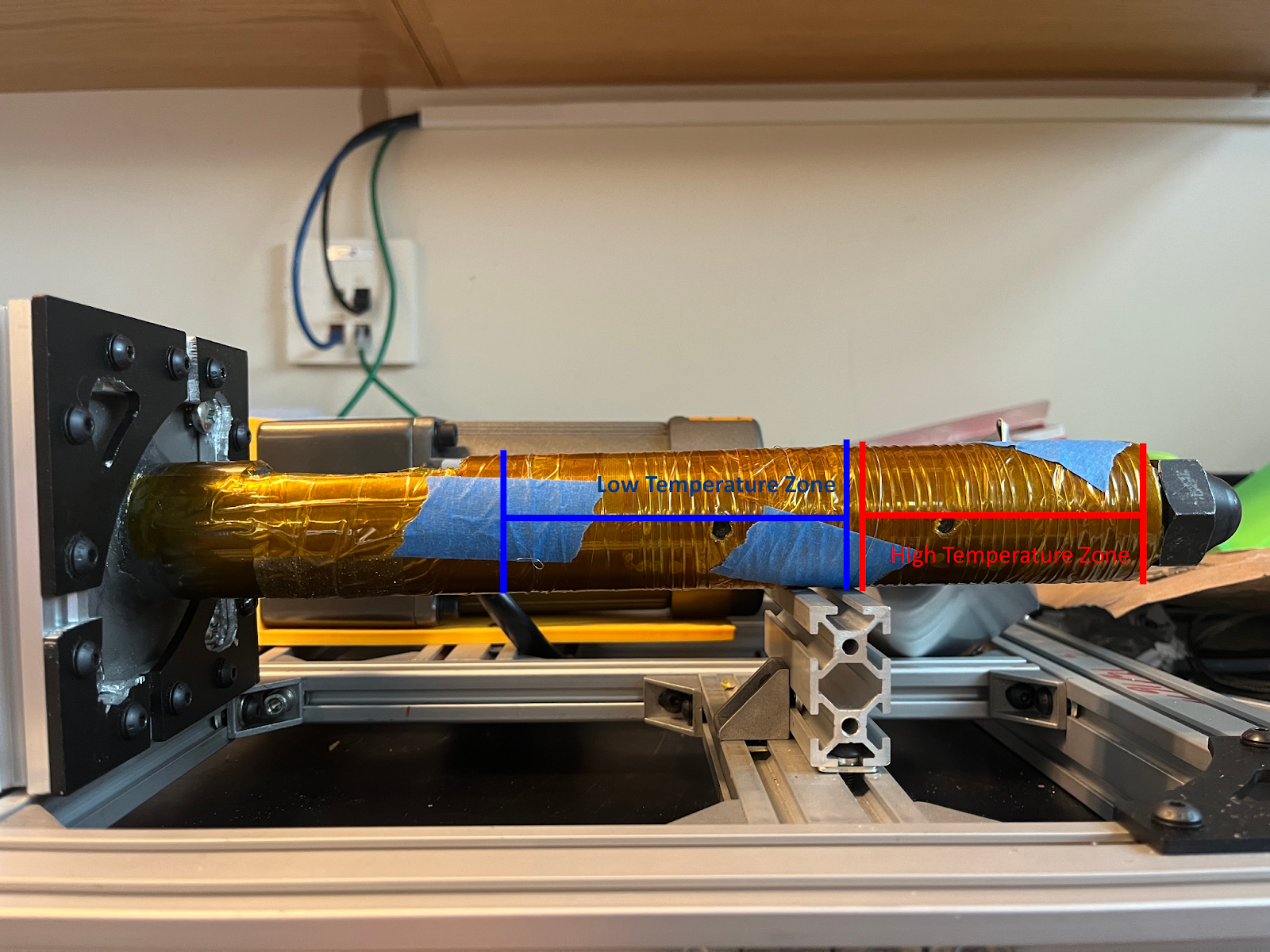
Figure 19: Location of Heating Zones
- Electrical Wiring
The wiring is set up in such a way that each heating element and InkBird temperature controller is run off of 110V. To achieve this a 12 gauge wire was connected in parallel running out of the Line and Neutral terminals of the power supply. Each wire is connected into one side of the terminal and a pass through is placed on the other side to continue the wiring.
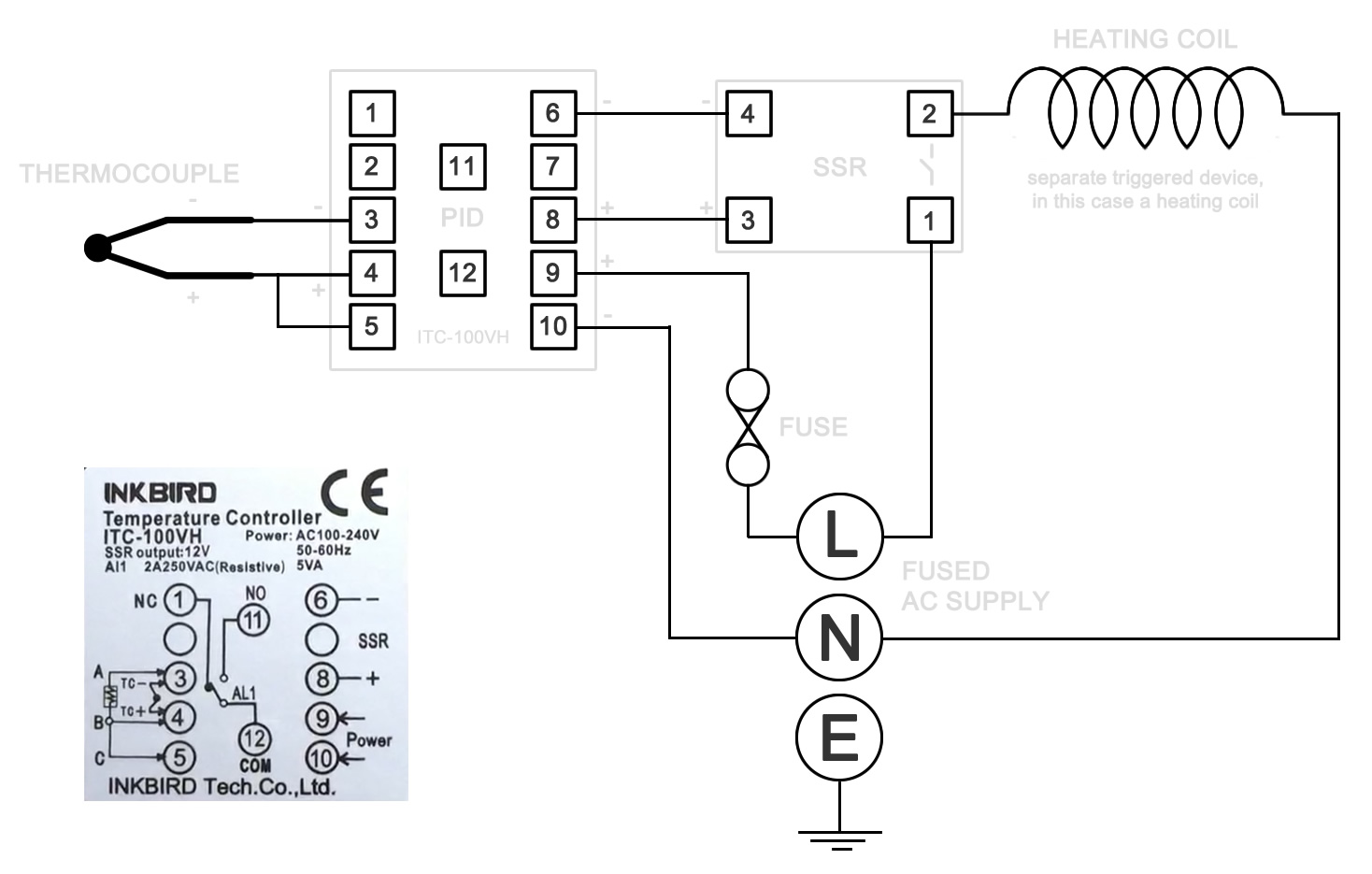
Figure 20: INKBIRD Wiring Diagram
- Parts Required 12 gauge wire, 22 gauge wire,
(also include how we wired the temp controller)
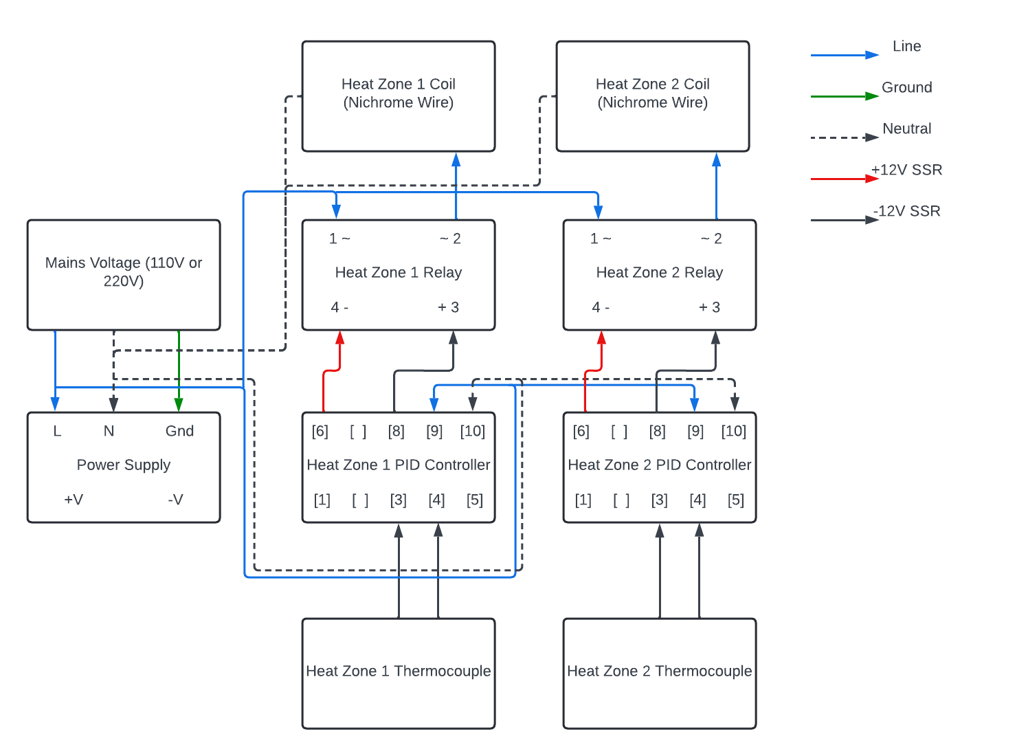
Figure 21: Recyclebot Wiring Diagram
Characterization Data
In the upcoming semesters we plan to implement more sensors into Recyclebot that will allow us to track important information about the filament. We plan on tracking the temperature of the barrel over time, and measuring the diameter of the filament as it is extruded. This data will help us quantify the quality of both Recyclebot and the filament it produces. We also plan on developing tests that can be used to determine the strength of the filament after it has been extruded. Proposed tests include varying the mixture of virgin resin to recycled material by weight, varying the speed of the motor while monitoring the output diameter, and varying the temperature of the heating zones while observing the characteristics of the resulting mixture.
Sponsors
Sponsored by Enterprise Manufacturing Initiative and the GM team