
Link to Previous Post (December 2022)
Background and Vision
To re-iterate the goal of this project; it is to create an open-source system that automates the chemical balance for residential pools. The final product itself will be relatively low maintenance and non-invasive to the existing filtration and heating system. This will be achieved by keeping the project separate from the existing pool system so that it can be implemented in a location that is both accessible and out of the way.
New Developments
There have been a number of improvements made this semester. The main focus was on the electronics system and wiring. Many of the components associated with the measurement system and electrical wiring were redesigned. The chemical mixing and delivery system was not touched this semester. However, the BOM has changed significantly, removing some unnecessary components and adding others.
Files
All design files can be found Here
Custom PCB Design
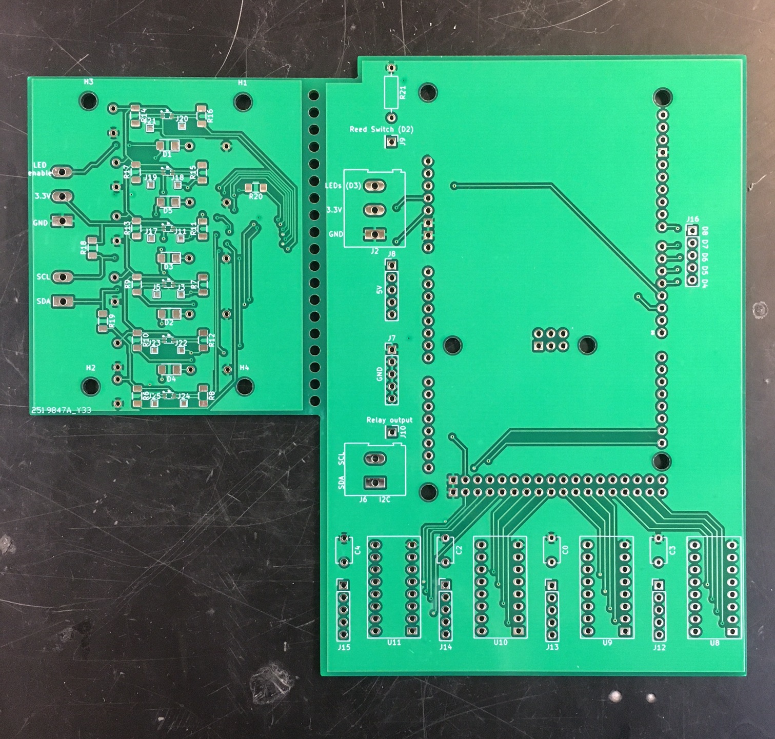
2 boards were designed to replace the complicated wiring in the device. The 2 boards were created in one schematic so that both could be ordered as one connected board. They can then be broken apart and used separately. Below are the details for each board as well as the components list for each. The boards were designed in KiCAD, and have a few custom footprints that can be found in the repository. The color sensor has a custom footprint and symbol, as well as the connector for the stepper motors. The footprint and symbol for the Arduino Mega were obtained from Here. This link can also be found in the README file in the repository.
Arduino Mega Shield
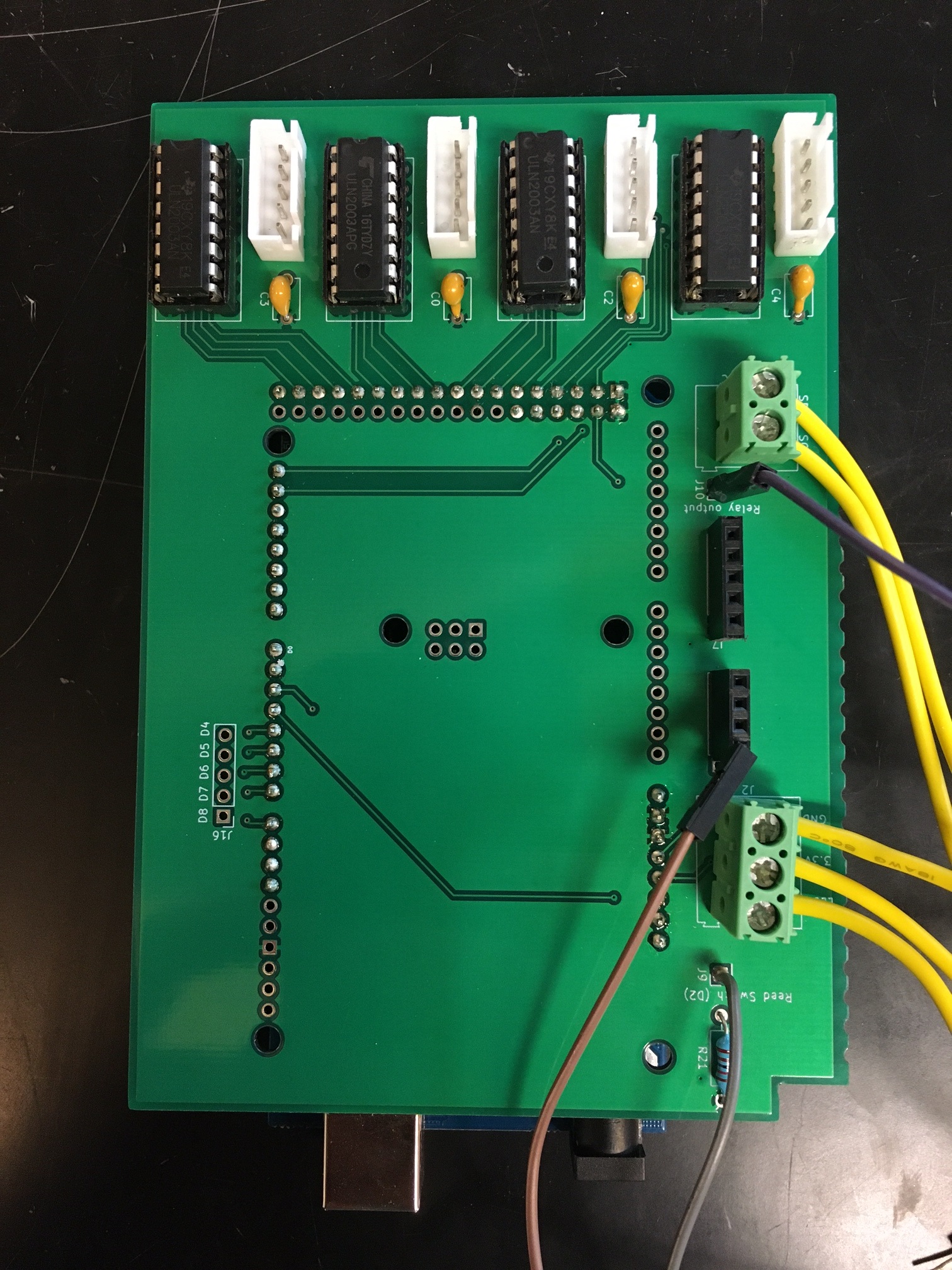
The Arduino Mega shield was developed to reduce the complexity of the internal wiring system. The 4 stepper motor drivers were integrated into this PCB, and screw terminals were added to break out the I2C communication pins, the enable switch, power, ground, and relay enable pins. There are also breakouts for a few unused digital pins and extra 5V and ground out to leave room for future development.
Most of the components for this board were sourced from the existing stepper motor driver boards. The components were de-soldered from the original boards and replaced onto the Shield board. The complete list of components for this board and their prices can be seen below.
Color Sensor Array PCB
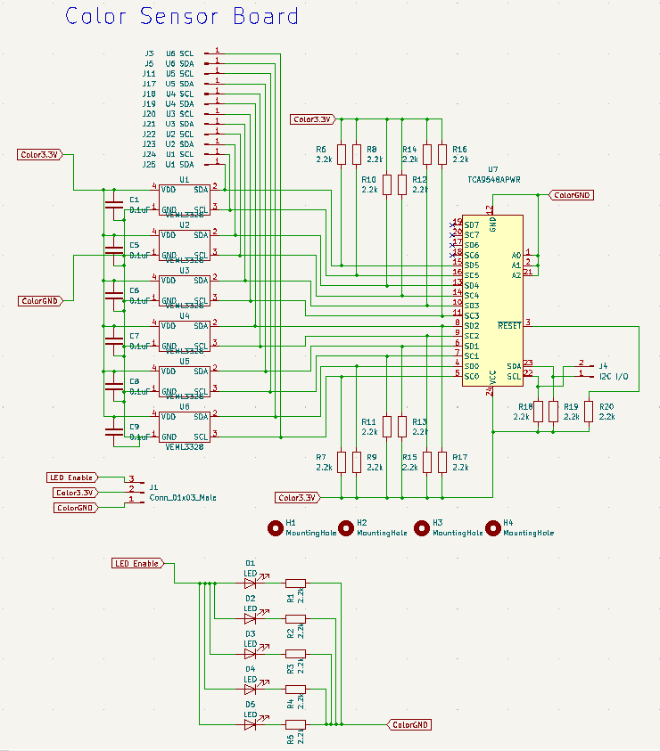
The system to read the pool chemical strips was completely redesigned. Instead of using one Adafruit AS7262 color sensor, the new design uses 6 individual color sensors, which are called VEML3328. The new sensors have a few new features and remove some old features that were not being used from the old sensor.
| Sensor | Adafruit AS7262 6-Channel Visible Light / Color Sensor | VEML3328 Color Sensor |
| Features | 6 Visible Channels Slow measurements (~3 / sec) $20 per board, $8 for an individual sensor Requires external memory Large Footprint (28 mm x 25 mm) | 3 Visible channels, Clear, IR Faster Measurements (~10 / sec) $2.80 per sensor Self-contained I2C controlled Small Footprint (2 mm x 1.25 mm) |
The main reason for finding a different solution to the color sensor was due to the speed of measurements of the old sensor. Taking only 3 measurements per second with only one sensor did not allow the data to have a distinct edge of where the pad was vs where the white space was on the strip. This effectively made the input data garbage. By changing from a system of swiping the strip through to a system of inserting the strip and leaving it there with 6 sensors instead of one, it eliminated the need to parse the data. There were no more edges necessary to detect, and there were significantly fewer inconsistencies.
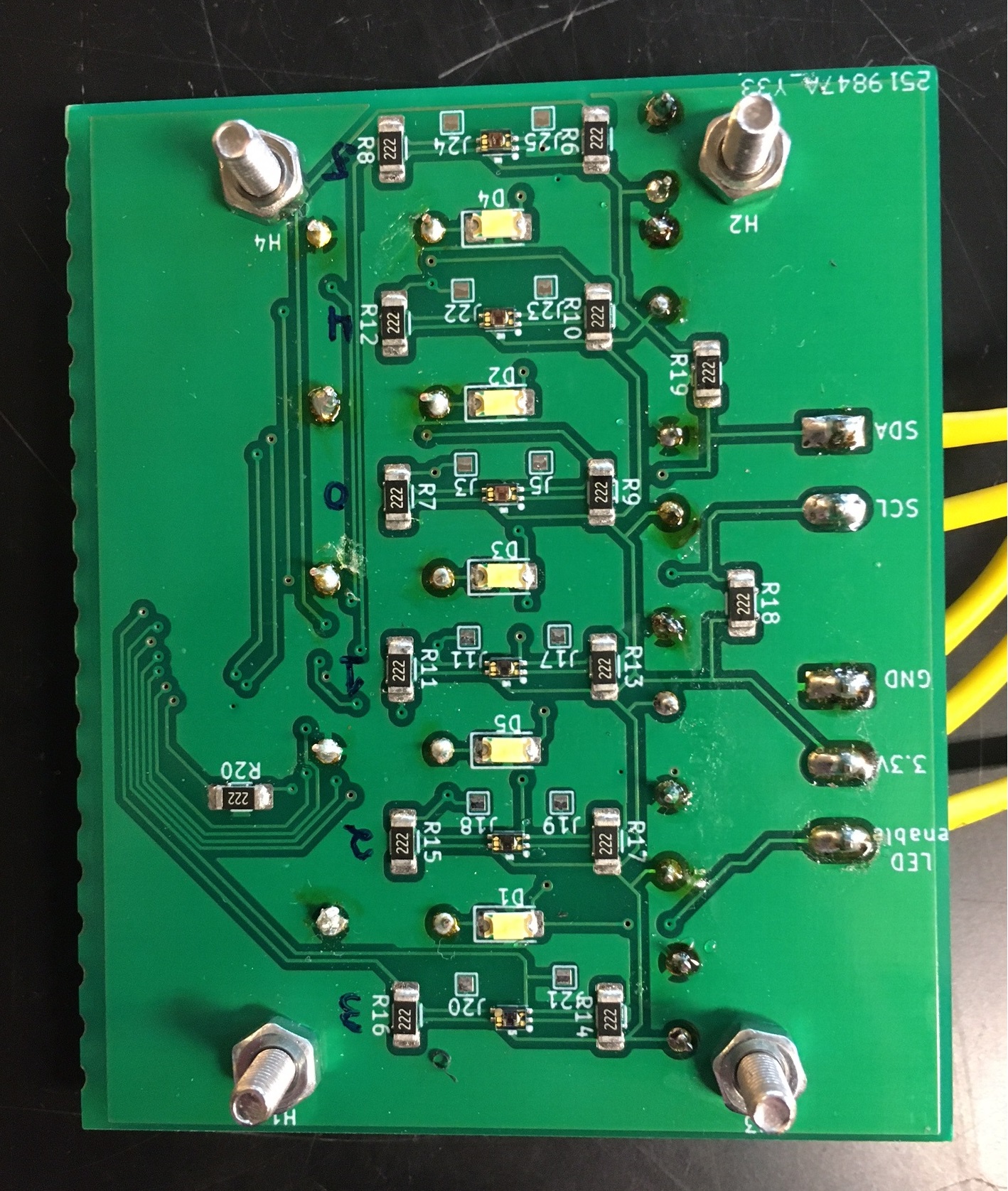
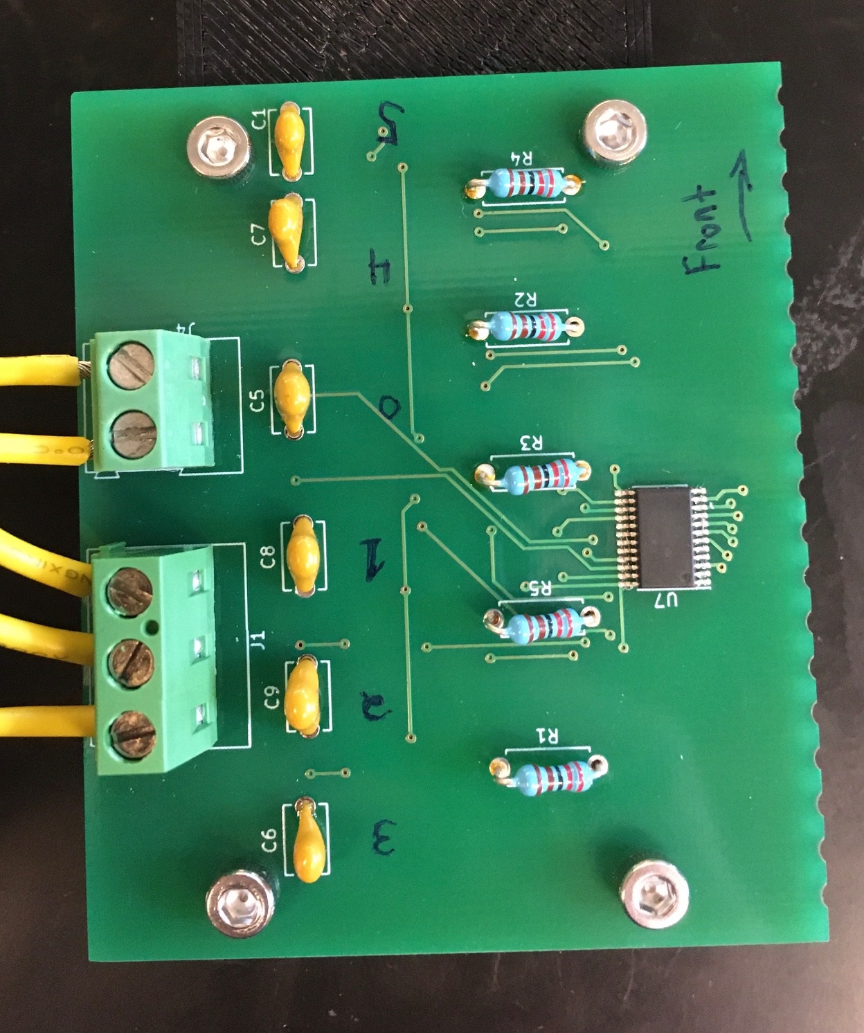
Here you can see the newly designed color sensor board with all the components populated. On the bottom side, the sensors are all spaced apart to line up with the test strip pads when inserted into the 3D-printed strip acceptor. On the top side, there is an 8-to-1 I2C Mux that is used to select each individual sensor when we want to measure from them. Every VEML3328 sensor has the same I2C address, so to communicate with more than one sensor the Multiplexor is necessary.
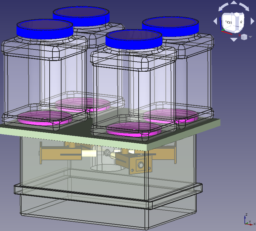
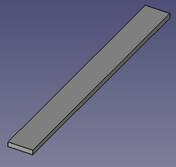
To allow the pool testing strip to line up correctly with the sensors this part was 3D printed. The slot lines up with the color sensors. This print was split into 2 separate prints to remove the need for support material. The second part is a flat rectangle that is attached to the bottom of the strip acceptor.
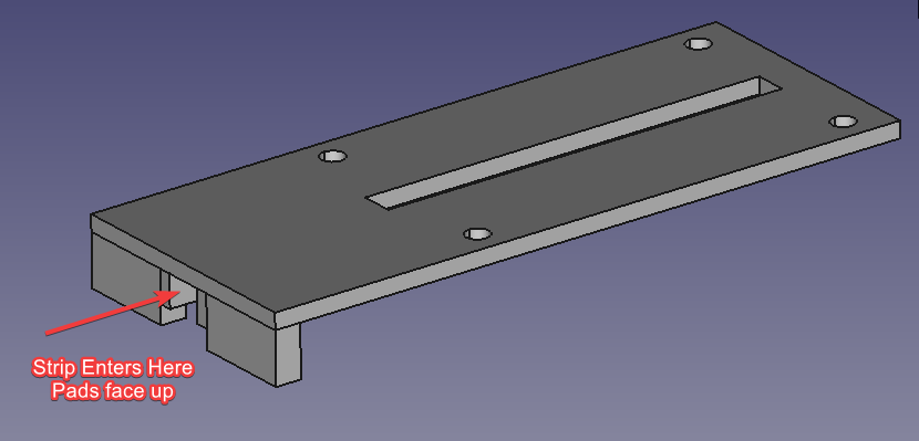
To assemble the color sensor array board, solder paste and a reflow oven were used. The pads on the board are hand-solder-sized in case a reflow oven is not available. The four M3 bolts are inserted through the PCB, then a nut is added as a spacer, then the bolts are inserted through the 3D printed part, then the other four nuts are added to secure the parts together.
PCB Bill Of Materials
| Part: | Quantity | Cost (estimated) |
| TCA9548A I2C Multiplexer | 1 | $2.09 |
| 2.2K 1206 SMD Resistor | 15 | $4.83 |
| White diffused 1206 LED | 5 | $2.85 |
| 2.2K Axial Resistor | 5 | $0.50 |
| 1.2K Axial Resistor | 1 | $0.10 |
| 1K Axial Resistor | 2 | $0.20 |
| Male pins | 7 | $6.72 |
| Female pins | 2 | $1.36 |
| 3 pin terminal screw block | 2 | $1.88 |
| 2-pin terminal screw block | 2 | $2.34 |
| 0.1 uF Capacitor | 6 | $1.38 |
| Color sensor VEML3328 | 6 | $15.44 |
| M3 bolt | 4 | $1.00 |
| M3 nut | 8 | $1.00 |
| Stepper Motor Driver Components | desolder from existing boards | |
| Estimated Total: $41.69 + tax |
Electrical Changes
For the internal wiring, there were a few changes in the power supply and delivery. The input power was changed from a 12V, 1.5A wall wort to a 5V, 3A wall wort. This choice was made because the 12V power was overheating the 5V regulator on the Arduino Mega, causing it to power cycle. The 12v also provided too much flow from the brushless dc pump. The flow rate was high enough to overflow the internal mixing chamber. By reducing the power to 5V the pump flow rate was reduced enough to no longer overflow the internal chamber, and the voltage regulator on the Arduino no longer overheated.
Previously to control the dc pump we had a dc PWM motor controller. This turned out to be ineffective as the pump has internal circuitry that does not allow for PWM control. This control issue was solved by simply removing the controller and reducing the input voltage.
To activate the device the previous design used a reed switch and a magnetic door to indicate when to start measuring. The reed switch was too inconsistent and would occasionally get stuck in the wrong state, breaking the code. To simplify the design, the switch was replaced with a normal push button.
One added electrical component is two indicator LEDs. There is now a green LED that turns on when the device is running and a red LED that turns on if the device failed to measure the pool chemical strip.
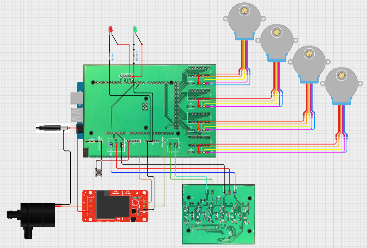
Here is the new electrical wiring diagram:
Code
Required Libraries:
The library used to control the VEML3328 color sensor can be found HERE
The library to control the stepper motors can be found HERE
Code Changes:
There are a few changes that need to be made to the code in the future, and some code changes depend on the specific use of the device.
Currently, the device does not determine the amount of each chemical to dispense to correct the pool composition. The code has the ability to read the pool strip and control all of the individual components such as the stepper motors, color sensors, button input, etc.
To determine the color of the strip the code takes an average of 10 measurements from each sensor and stores them in an array. The array of measurements is a 2-dimensional array of each strip pad, then the RGB values of each reading. The measurement data is then compared to a distance table that was filled out through experimentation. Water was chemically balanced to each specific reading, then a strip was measured by the device and recorded in the lookup table. The data is compared through a simple distance calculation. Whichever entry in the table is the shortest distance from the measurement is recorded in an array called “stripResults”.
These values could then be used to determine how much chemical powder to add to fix the composition. The skeleton of the code is there to accomplish this, but it is commented out and does not function.
Uploading the Code
Download the “OpenWaterFinalCode.ino” file from the repository and open it in the Arduino IDE. Plug in the Arduino Mega and upload the code.
Bill of Materials
| Part | Quantity | Price |
| Food storage containers | 4 | $2.97 |
| Flexible Tubing | 4 ft | $5.60 |
| Drill Bits (5/16) | 4 | $5.99 |
| Water Pump | 1 | $29.99 |
| Adafruit Color Sensor | 1 | $19.95 |
| PETG 3d printer filament | 1 kg | $19.99* |
| Stepper motor (set of 6) | 1 | $13.99 |
| Arduino Mega | 1 | $20.99 |
| Waterproof Enclosure | 1 | $35.99 |
| Relay module | 1 | $6.79 |
| Pool Test Strips | 1 | $22.49 |
| 5V power supply | 1 | $7.00* |
| Flexi Arm | 1 | $10.95 |
| Waterproof Barrel Connector | 1 | $12.99 |
| M2 bolts | 4 | $1.00* |
| M2 nuts | 4 | $0.50* |
| M4 bolts | 8 | $1.00* |
| M4 heat inserts | 8 | $1.00* |
| LEDs | 2 | $1.00* |
| 22 awg wire | ~5ft | $5.00* |
| Total: 225.18 + tax |
3D Print Parts
| Name | Qty |
| StripAcceptorV2 | 1 |
| StripAcceptorV2-Bottom | 1 |
| Bit Adapter | 4 |
| Dry Mover Top | 4 |
| Dry Mover v4 | 4 |
| Mixer v5 | 1 |
| PCB Holder | 2 |
| Button Holder | 1 |
Assembly Instructions
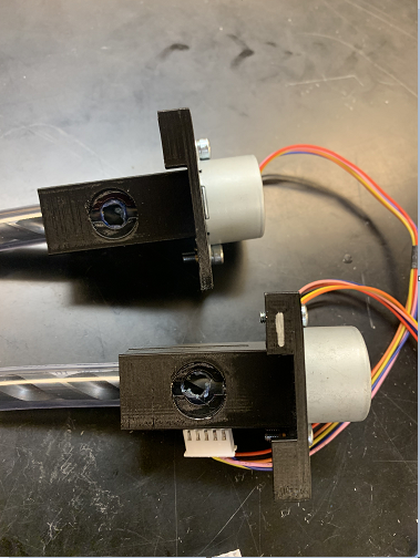
Dry Mover Subassembly
- Using an angle grinder, cut all four drill bits down to 87 mm
- Using a bench vice, press the bit adapters into the newly cut bits
- Press the bit adapter onto the motor making sure the motor shaft fully seats into the adapter.
- Use a soldering iron to set the heat inserts into place on the dry mover parts
- Using m4 bolts, screw the assembled motors into the dry movers
- Add this assembly to the motors to part using heat inserts or nuts and m4 bolts
- Cut 4 60 mm long sections of ⅜ ID tube
- Straighten this tube using a heat gun if necessary
- Install the tube into the dry mover assembly as shown
- Using a marker, mark the area hole that needs to be made at the top of the tube
- Cut the tube using a chisel-tipped soldering iron set to 325 c, and clean up using a 10 mm drill bit on a low-speed drill
- Reinstall the tube into the dry mover assembly, making sure the hole in the tube lines up with the hole in the printed part
- Add a small amount of glue to the edge of each side of the mover to prevent the tube from turning when the bit is actuated.
- The assembly is printed with two support tabs on top. Using a bench vise, remove the left tab from two of the dry movers and the right tab from the other two
Enclosure Subassembly
- Using a 3 mm drill bit, drill through the third stud from each corner on the closure and hinge sides of the enclosure
- Drill through the center of each of the 4 storage containers using a 3mm drill bit
- Center the support board onto the bottom of the mixer, mark through the studs and drill a 3 mm hole at each mark
- Using 4 40mm M4 bolts, fasten the containers, support board, and housing together.
Mixer Subassembly
- Glue the mixer top to the top of the exit tube inside the mixer
Dry Mover/ Mixer installation
- Press the 4 mixer tops into the dry mover assembly
- Fit the four dry movers into the mixer
- With the dry movers in the mixer, turn the mixer upside down and place it into the enclosure.
- Center the mixer in the enclosure and slot the 4 mixers in place between the corner studs in the enclosure
- Ensure the backs of the dry movers, dry mover tops, and mixer are all sitting flush against the bottom of the enclosure
- Using a small amount of hot glue or a marker, tack or trace the dry mover tops and mixer in place
- Remove the dry movers and mixers, leaving the mixer tops in place
- Drill a 10 mm hole through the center of each dry mover top going through the bottom of the enclosure, support board, and storage containers
- Remove the dry mover tops
- Glue the dry mover tops in place using enough glue that a seal is created between the parts and the housing
- Using silicon sealant, seal the four ⅜ ID tubes into place in the mixer
- Apply glue and silicon sealant to the top surfaces of the dry movers and mixer, and silicon sealant around the top of the mixer
- Install the mixer and dry mover into the enclosure ensuring there is a good seal between the top of the mixer and the enclosure
Plumbing and I/O
- Mark 15 mm down the ⅝ ID tubing
- Using a 5 mm drill bit, drill two holes opposite each other on the 15mm line
- Using silicon sealant, install the tubing into the bottom of the mixer making sure the holes in the tube are aligned with the relief holes in the mixer
- Using silicon sealant, install the ⅝ ID tubing onto the mixer inlet
- Clamp the inlet tubing in place with a zip tie to prevent leaks
- Drill 20 mm and 8mm holes on the hinge side of the enclosure as close to the sealing edge as possible.
- Feed the corresponding tubes through; seal with silicon sealant
- Cut a few small holes in the return hose so that it does not form a seal when submerged in the water.
- Drill a 4 mm hole, feed the pump wire through, and seal with silicon sealant
- Using a rotary tool, cut a 12 mm square into the opposite (closure) side of the box, 35mm from the sealing edge and 80 from the right side of the enclosure
- Using silicon sealant, install the strip acceptor housing
- Drill a ½ inch hole 70 from the sealing edge and 65 from the right side of the enclosure
- Using silicon sealant, install the waterproof connector
PCB Installation
- Install the dry mover subassembly into the bottom of the container, then connect the stepper motors to the Arduino shield.
- Slot one of the PCB holder prints onto the side of the PCB.
- Insert the PCB into the box and hold the PCB holder against one of the walls until the PCB is in a place where it can sit and the lid can still close.
- Glue the PCB holder in that position, then you should be able to remove the Shield whenever and replace it in the same position.
- Cut a hole in the side of the box that is slightly larger than the opening to the strip acceptor 3D print.
- Take the second PCB holder print and slot it onto the color sensor array board. Hold the board so that the entrance lines up with the hole that was just drilled.
- Glue the second PCB holder in place, then you can remove and replace the color sensor array in the slot when putting the rest of the device together.
Button and Indicators
- Cut a hole in the side of the device wherever desired the size of the “button holder” 3D part.
- Glue the button holder in place with the button inset in it.
- Place the LEDs behind the button so that the light shines around the button
Wiring
- Prepare cables to run power to each of the components in the device as shown in the schematic. Run +5v and ground to the Arduino Mega and the relay.
- Connect the GND wire of the dc pump to GND directly. Insert the positive wire into the “Normally Open (NO)” connector on the relay and the +5v from the power supply to the COM connector. Connect a wire from the labeled “Relay out” pin on the Arduino shield to the “IN” or “Control” connector.
- Wire the rest of the components according to the wiring diagram
Using the Device
- Plug the 5V power supply into the waterproof connector on the side of the device.
- Place the device on the side of the pool with the pump under the water and the return tube over the side of the pool.
- Dip the pool testing strip into the water and wait a few seconds for it to be stable
- Insert the strip into the side of the device until it can’t go in anymore.
- Push the button to start the device
Functional Requirements
- The entire device will have design files originating entirely from free and open-source software (5%)
Completed: Files were designed with FreeCAD, KiCAD, and in the Arduino IDE - The device shall read the chemical composition of pool water (15%)
Completed: the color sensor array can determine the strip colors - The device shall interpret the readings and calculate the correct chemical to dispense (15%)
Partial: the device has some hard code to dispense chemicals to correct PH - Research and experimentation will be conducted to determine the most effective sensor combination for accurate, repeatable readings (10%)
Completed - The device shall have a custom PCB to integrate the components easily (15%)
Completed: 2 PCBs were designed to replace a lot of the wiring and component complexity - The device shall be able to accurately and controllably dispense chemical powders (15%)
Completed: The auger system can accurately dispense approximately 0.07tsp per revolution - All custom parts in the device shall be entirely 3d-printable (5%)
Completed - The device shall dissolve the powdered chemicals before dispensing them into the pool (10%)
Partial: the powdered chemical occasionally makes it back into the pool before it is completely dissolved - The device shall be waterproof (5%)
Partial: the device is splash-proof, but cannot be submerged - The device shall be self-contained (5%)
Completed
Value Added Goals
- The device shall indicate to the user when it is running and whether or not it failed (5%)
- The device has an integrated low-power mode and runs on low-power consumption
- The device software shall have a custom I2C library to interact with the sensors
The first value-added goal was implemented into the device. The rest of the value-added goals were no longer applicable to the project anymore, as the sensor array does not need a “low-power” mode and draws very little when not in immediate use. The custom I2C library for controlling the sensors was also unnecessary because there were already existing libraries to control the VEML3328 sensors individually, and the multiplexing code was as simple as a single written function.