
Open Source Open Platform Tesla Coil
Fall 2023
Joel Diccion – Electrical Engineering
Nathan Fisher – Electrical Engineering
Tom Powell – Electrical Engineering
Dr. Shane Oberloier – Enterprise Advisor

Michigan Technological University
Open Source Hardware Enterprise
Houghton, MI 49931
Table of Contents
- Previous Year Summary
- Acknowledgements
- Introduction
- Objectives and Constraints
- Objectives
- Constraints
- Primary Circuit
- Analyzing Rectifiers
- First Iteration
- Second Iteration
- Final Wiring Diagram
- Analyzing Rectifiers
- Secondary Circuit
- Assisted Winding
- Resonant Frequency
- IoT Website
- Final Comments Coil Assembly
Appendix A. Links
I. Previous Year Summary
This is the first semester of Tesla Coil. The time budgeted is to have a functioning Tesla coil by the end of the Spring 2024 semester.
II. Acknowledgements
The Open Source Tesla Coil team would like to thank those involved within the Open Source Hardware Enterprise for the opportunity to work on this project and for the help provided with general lab functions. The team would also like to thank Dr. Shane Oberloier for his guidance in this project and for creating an enterprise environment conducive to learning and collaborating.
III. Introduction
Teammates Joel Diccion and Nathan Fisher had the idea to make a tesla coil that can play music. The time budget for this semester for the project was dedicated to designing and manufacturing a functioning tesla coil. To fulfill the requirements that are to be set in the Spring semester, the coil should be a solid state tesla coil (SSTC). The tesla coil team worked together throughout the semester to find a working schematic of as SSTC, automate the coil winding process for the secondary circuit, 3D print the structures needed for the coil and circuit housing unit, and assemble the primary circuit.
IV. Objectives and Constraints
A. Constraints
The overall goal of this project is to create a functioning SSTC. All of this was to be done utilizing open source manufacturing practices as well as consumer-grade components to keep the cost as low as possible. Here are the goals set for this project:
- Open-Source Part Files for Modification
- While all of the original parts were designed in Fusion 360, a paid CAD software, none of the features specific to Fusion 360 were used. As such, any part could have been designed in OnShape or any other free CAD software. The files created in Fusion 360 were saved as non-proprietary files, so any CAD software can open and edit them.
- 3D Printed Components
- Allows for low-cost manufacturing of new and existing components
- Have a tesla coil that makes noise
- Primary circuit should conduct current
- Secondary circuit should be coupled to the primary
- A housing unit should be made for the loose electrical components
- The resonant frequency of the secondary coil should be measured
- The pitch should be controlled precisely and accurately
- There should be an IoT website that can be connected to an interrupter
- Research and implement a safety procedure
- Should include instructions on operation and safe spectating
- Create an IoT website that has the potential to connect to a microcontroller
B. Constraints
Here are the limitations placed to keep the design accessible to any open source enthusiast:
- Open-source tools will be used to manufacture the coil housing unit
- 3D printing will be the basis of manufacturing for this project.
- The budget should remain under $100
- Complete the project goals within a 1 semester time frame.
- Tools in the OSHE lab are to be used for electrical assembly and analysis
- Resonant frequency will be found using the function generator and oscilloscope
- Soldering the prototype board should be done with the soldering setup in the OSHE lab
V. Primary Circuit
The primary circuit took a majority of the semester to produce. The first half of the semester was spent considering different designs and weighing their feasibility and effectiveness. The second half of the semester was spent manufacturing the final circuit design.
A. Analyzing Rectifiers
To create a SSTC, the wall outlet AC voltage needs to be rectified into DC. It is also recommended to step up the voltage to reduce the current in the primary circuit which makes components cheaper and easier to find while also making the system more efficient.
1. First Iteration
The first iteration of the rectification circuit was a full bridge circuit. It was compelling due to its simplicity and low cost. The cons outweighed the pros for this circuit as the voltage isn’t stepped up as well as the circuit has lots of distortion which makes it almost unusable due to inefficiency. The schematic to the first iteration is shown in figure 1.
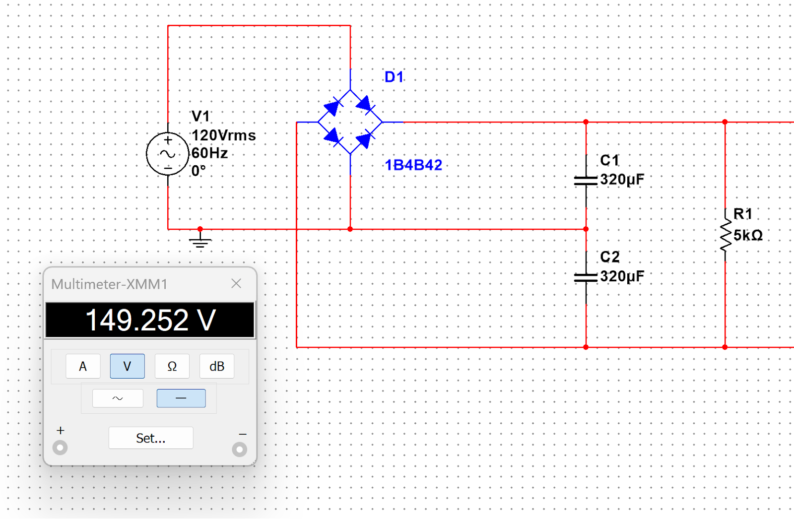
Figure 1. This is the first design consideration for the rectifier.
2. Second Iteration
The second iteration of the rectification circuit is shown in figure 2. The pros for this circuit are that it is also low production cost and it could output close to 340 Vdc. The cons are that it was impossible to simulate the coil impedance to pick an appropriate value for R2, which is used as a current limiting resistor, and that there would be a very large current flowing through the capacitors. Having a large current flowing through the capacitors is not ideal because any capacitor that was rated for the required voltage and current that the coil produces had a high equivalent series resistance (ESR). A high ESR meakes for a less efficient circuit and more heat within the capacitors that could be problematic in practice.
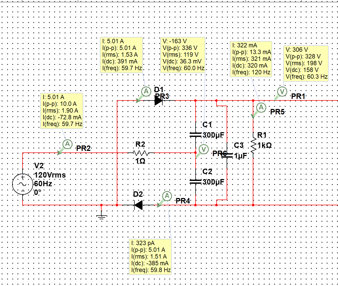
Figure 2. This is the second iteration of the rectification circuit
B. Final Wiring Diagram
The final design for the rectification circuit is inspired from figure 3. The pros of the circuit are that someone else already designed and manufactured this as a proof of concept and it shows 340 V across the primary coil. The cons are that it is the most complex and expensive circuit out of the ones considered so far. The team went with this design inspiration because there was already proofs of concept for this online. The entire design can be seen in figure 4. The inspiration is a fully analog circuit. Our team modified it so that it can be controlled digitally in order to play music on it in the future. Table 1 shows the BOM for the primary circuit components. A link to the source of this schematic can be found in Appendix A Link 4.
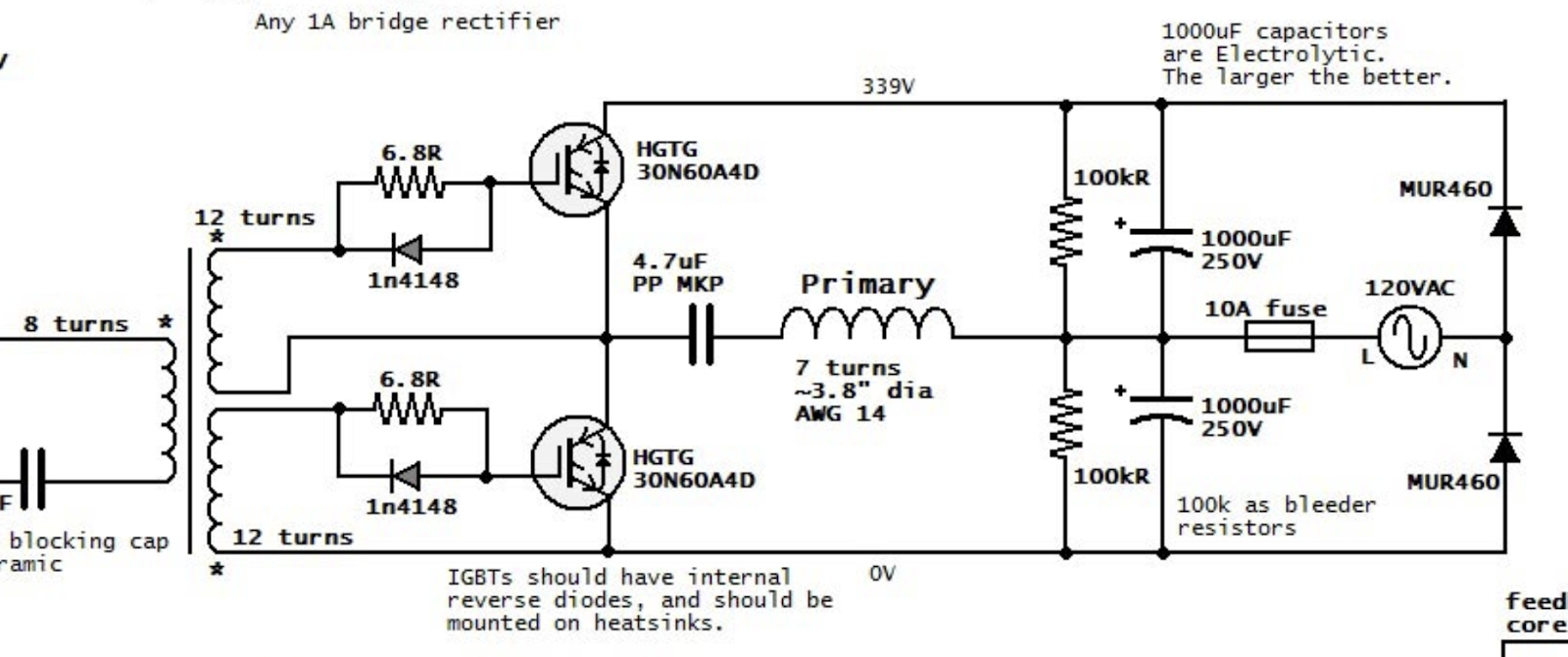
Figure 3. This is the inspiration for the final design of the rectifier circuit.
Figure 4. This is the design inspiration for the primary circuit for the SSTC.
| Component | Quantity | Total Cost |
| Gate driver | 1 | $1.23 |
| IGBT | 2 | $17.66 |
| 100k OHM resistor | 2 | $0.13 |
| 1 mF, 250 V capacitator | 2 | $11.28 |
| 10 A, 125 V fuse | 20 | $8.86 |
| 4.7 uF MKP capicator | 1 | $5.88 |
| Fuse housing unit | 1 | $0.68 |
| Inductive core | 1 | $1.21 |
| Prototype board | 1 | $11.28 |
| Rectifier diodes | 2 | $3.68 |
| Protection diodes | 2 | $0.78 |
| 6.8k OHM resistor | 2 | $0.78 |
| Thermal pads | 2 | $0.58 |
| Wire for connections | 1 | Free (found in lab) |
| Housing unit | 1 | Free (3D printed) |
| Heat sinks | 2 | Free (used components from lab) |
Table 1: This is the BOM for the primary circuit. The total cost was $64.03. Note that the cost is for the bare minimum components. Extra components were ordered in anticipation of failure.
VI. Secondary Circuit
Note that the secondary circuit is much more simple than the primary. The only cost was 32 AWG enameled copper wire as everything else was found for free lying around. The toroid and tube were 3D printed. The enamel around the wire is optional for longevity and the tin foil on the toroid was found lying around.
- Assisted Winding
During construction of the secondary circuit, it became apparent that winding the coil by hand would be infeasable in terms of time and construction quality. It was decided that an assisted winding machine would have to be built. Open source resources were available for a coil winding machine, so this is what was followed. The video for the coil winding machine can be found in Appendix A Link 1, and the STL files can be found in Appendix A Link 2. The printing and assembly of the winding machine was straight forward, with the only modification necessary to bring a scaling factor to all of the parts to match the coil diameter. The complete coil winding machine can be seen in Figure 5. The winding machine was powered with a variable DC power supply, which allowed for fine control over the winding speed.
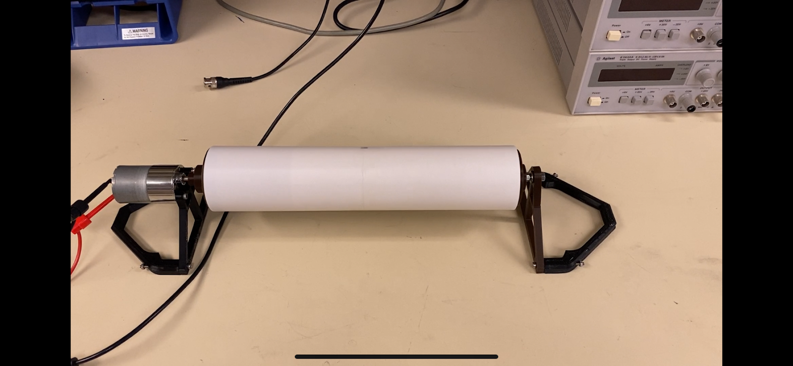
Figure 5: Coil Winding Machine with empty coil.
- Assisted Winder Assembly and Use
The only special part needed for the assisted winder is the gear motor. For this, any gear motor will do, but we used a 12V 100 RPM motor from Greartisan. Once the motor is chosen, simply scale the STL files found in Appendix A to match the mount spacing on the motor. For our motor, a scale factor of 2565.79% was used. This should result in a suitable fit on all parts, but make sure to use the measure function in your CAD software to ensure proper alignment.
It should be noted that CAD files will have to be made for the diameter of the pipe you are using, as the supplied STL files are for a half-inch pipe (The half-inch pipe can also be used to develop a scale factor, simply scale the part to be exactly half an inch in diameter, and apply this factor across the board).
Once the parts are printed, assembly can be done with any basic fastening hardware. We opted for M3-sized nuts and bolts since that is what was on hand.
It is recommended that two people wind the coil, since holding the wire spool is awkward with only one person. The motor leads should be plugged into a variable DC power supply so that the speed can be precisely controlled. The winding of the coil has a learning curve, so make sure to have extra wire for when you mess up. The video in the appendix shows the ideal winding method, you should use your fingernail to keep the wire up against the previous wrappings. Also, the process is hardest when spinning slowly, use a high RPM for best results (70 -90 RPM works well).
- Resonant Frequency
After the secondary circuit assembly was complete, the resonant frequency needed to be determined. The method for determining the resonant frequency was to apply various frequency sine waves of constant amplitude across the secondary circuit, and find the frequency that results in the greatest voltage gain. An oscilloscope was used to record and compare the input and output voltage waveforms. Through experimentation, the resonant frequency was found to be approximately 53 kHz. This is lower than expected, but still of a reasonable value.
To recreate our setup, connect the function generator directly to the oscilloscope. Connect the positive terminal of the function generator to the bottom of the coil. Connect the positive terminal for the probe on the coil on the toroid on the opposite side of where the wire is connected. Leave the ground floating as the coil acts as an antenna in this scenario. The oscilloscope captures where resonant frequency was found can be seen below.
Figure 6. This is the oscilloscope capture of the coil at resonant frequency. The green waveform is the measured waveform from the coil and the yellow waveform is the waveform from the function generator.
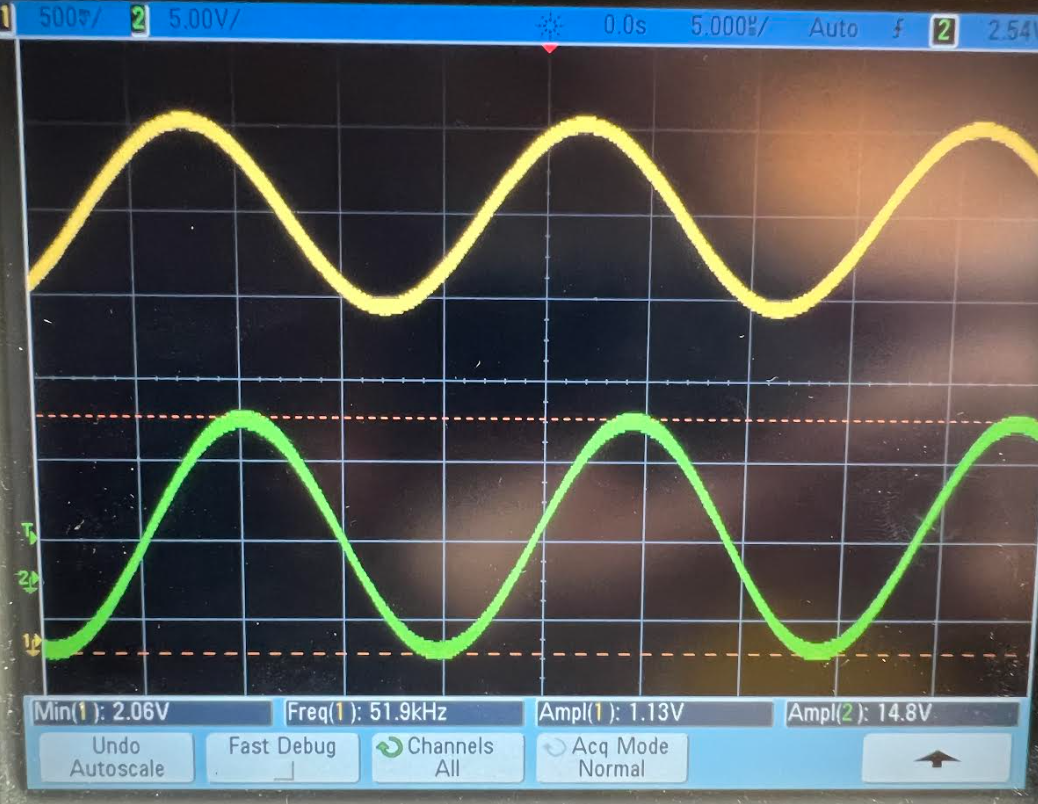
Figure 7. This is the oscilloscope capture of the coil below resonant frequency. The green waveform is the measured waveform from the coil and the yellow waveform is the waveform from the function generator.
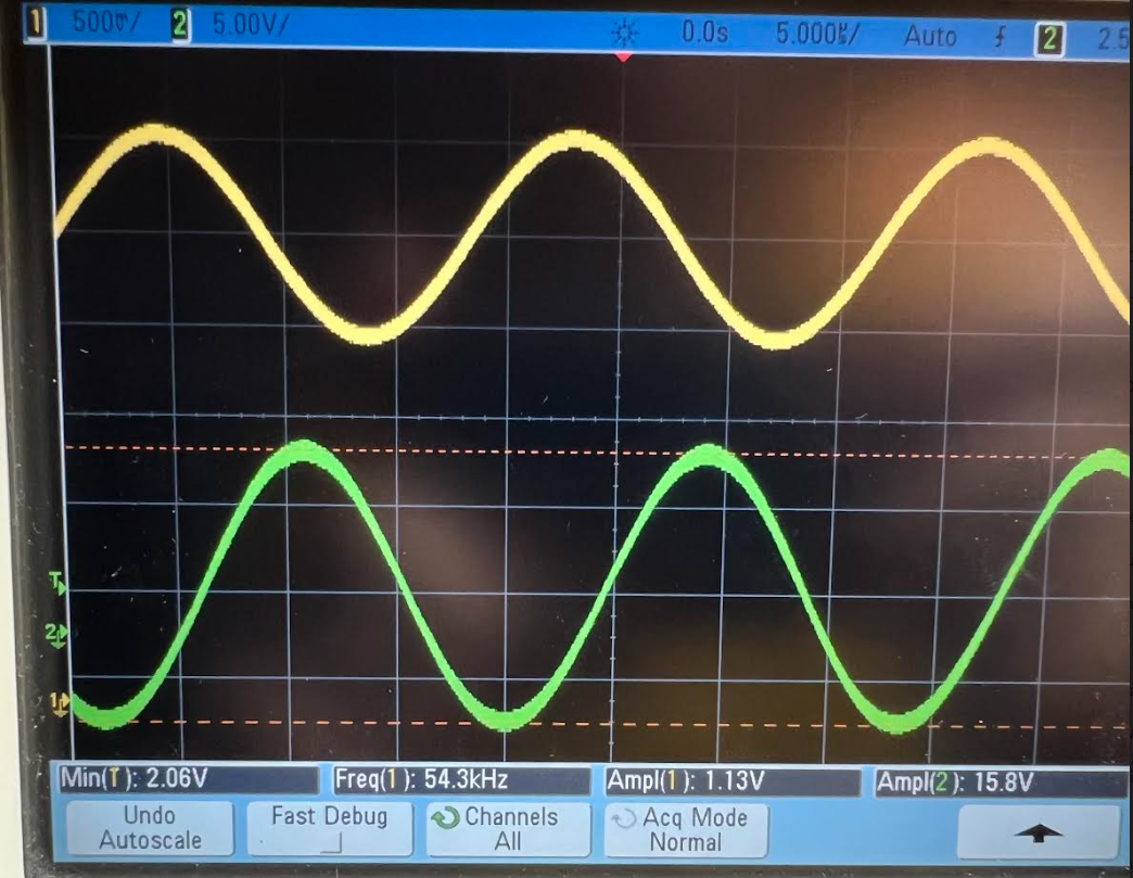
Figure 8. This is the oscilloscope capture of the coil above resonant frequency. The green waveform is the measured waveform from the coil and the yellow waveform is the waveform from the function generator.
VII. IoT Website
There isn’t much to say about the IoT website as most bandwidth this semester was spent on designing and manufacturing the physical coil. The website isn’t currently accessible to the public and no pictures will be shared due to privacy concerns. It should be noted that “000webhost” is the website used to make the IoT website as it is free and there is proof of concept of someone connecting an Arduino nano to their website.
VIII. Final Comments Coil Assembly
While it is the intention to 3D print components to minimize cost and maximize reproducibility, it should be noted that the OSHE labs were unreliable throughout the semester. That hindered progress. It should also be noted that the oscilloscope captures were taken in a picture on an iPhone because the captures on the flashdrive don’t should the measurements made so those captures are too arbitrary to be useful. A final note that the soldering setup in the OSHE lab is less than ideal, so one of the OSHE team members used their personal soldering setup in order to expedite the manufacturing process.
Appendix A: Links
| Link Number | Description | Link |
| 1 | Coil Winding Machine Video | https://www.youtube.com/watch?v=6zdD5Rkx8OE&ab_channel=HyperspacePirate |
| 2 | Coil Winding Machine STL Files | https://www.thingiverse.com/thing:4931100 |
| 3 | IoT website setup tutorial | https://www.instructables.com/Build-Own-Secured-PHP-IOT-Website-Free-Arduino/ |
| 4 | Primary circuit design inspiration | https://www.instructables.com/Build-Own-Secured-PHP-IOT-Website-Free-Arduino/ |
| 5 | OSF repository | https://osf.io/y2wfc/ |