
Open Mobility
Project Update 4
Tasks Completed
- Motor Mount Prototype Designed and Implemented
- Wheels Researched
- CAN protocol on VESC researched (preliminary)
To Do List
- Revise Motor Mount for better fit
- Have CAN working on breadboards
- Continue VESC CAN research
- Begin designing undercarriage
Project Update 6
Tasks Completed
- CAN libraries configured and studied
- CAN communication successfully established between both ESP32 modules with data transmission
- CAN communication libraries successfully integrated with radio receiver interpretation code
To Do List
- Order Wheels and belts
- Design of undercarriage
- Establish CAN communication with the VESC, specifically sending and reading duty cycle commands from the CAN bus.
Concerns
- Timeframe for receiving orders
- Receiving telemetry from VESC and logging
Project Update 7
Tasks Completed
- PWM interpretation algorithm fixed to eliminate sampling errors
- VESC integration implementation begun, duty cycle interpretation adjusted to account for VESC requirements, libraries found
- Board design revised for better load distribution
To Do List
- Order Wheels and belts still, must do this week
- Continue design of undercarriage
Concerns
- Timeframe for receiving orders is largest concern
- Would like to see some systems working together this week
Project Update 8
Tasks Completed
- CAN on control slice configured for VESC compatibility, VESC successfully reads duty cycle commands over the CAN bus
- Battery Slice code written, configured for individual cell voltage monitoring via the BMS cable
- Wheels and Belts ordered
- Undercarriage design prototype completed
- Telemetry logging researched, hardware aquired
- Battery voltage monitoring solution found and decided on after encountering implementation issue
To Do List
- Finalize Undercarriage design, begin printing
- Integrate Battery Slice controller with hardware design, output battery telemetry over the CAN bus to control slice
- Finalize drive chain design once wheels are received
Concerns
- Battery Voltage Monitoring System, specifically the hardware implementation
- Drive chain integration
Project Update 9
Tasks Completed
- Motor Drive assembly loaded into CAD
- Motor Mount redone and many iterations gone through. Drive chain connects securely to the wheel
- Motor and Wheel pully designed and printed. Final iteration complete
- Undercarriage design continued
- Board risers printed and installed. Board rolls freely and is usable as a standalone device with the current wheels. No wheel bite issue and feels stable.
To Do List
- Finalize Undercarriage design, begin printing
- Print final revision of motor mount
- Integrate subsystems
Concerns
- Time to print undercarriage
- New receiver delivery date
Project Update 10
Tasks Completed
- Motor mount slightly revised
- Telemetry code updated to load float values
- Battery slice dropout detection implemented
- Undercarriage design and mounting configuration completed. Fully printed and installed
- New front board slice printed with better load distribution. Works well with no stress cracks near the force focus points
- New receiver installed and tested. Control code was re-written to implement torque control (current control).
- All systems integrated and mounted securely inside the undercarriage
- Board is done!!
To Do List
- Clean up some of the code
- Document project
Concerns
- None
Project Update 11
Tasks Completed
- Final report draft completed
- Test runs with board performed, resulting in motor mount snapping 🙁
- Likely failure mode is over-tension on the belt and insufficient top/bottom thickness setting for 3D printing
To Do List
- Final Report
- Capstone Presentation
- Revise/Reprint Motor Mount
Concerns
- None
Work Log 1 (9/8/2024 – 9/14/2024)
Below is a sketch of what we would like to accomplish by the end of the fall semester:
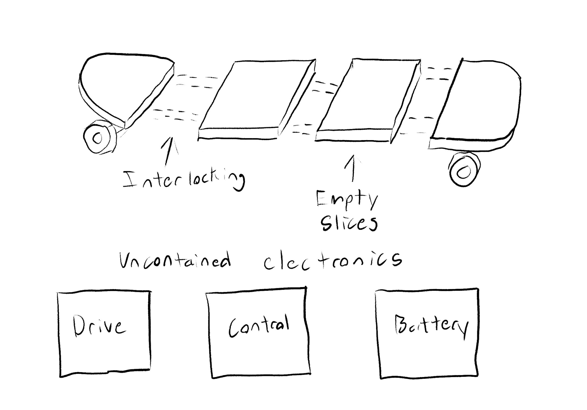
The slice interlocking mechanism is ambiguous at this point. Our reference design uses straight metal rods cut to the length of the board, but this will not be feasible with a modular design. Having the electronics housed in the slices is also not a goal for this semester, simply operational.
So far, we have assigned initial tasks to help get the project off the ground. These tasks include researching other electric boards (performance and components) and designing slice interlocking.
To-Do List
- Design a preliminary slice interlocking mechanism
- Draft meeting minutes
- Detremine delegations for next week
Work Log 2 (9/15/2024 – 9/21/2024)
As a capstone member, I feel that we are now in a good place regarding how prepared the team is. I have set up a structure of weekly deliverables that each subsystem is to meet by the next meeting, every Monday in our case. This should ensure that we always have direction on the project.
Previous To-Do List Dissection
- Prototype interlocking mechanism has been determined. We will be using coupling nuts to attach the threaded rods together. This should provide sufficient reconfigurability without sacrificing structural stability.
- Meeting minutes and deliverables templates have been made and will be refined as time goes on.
- As stated, delegations are being handled. Alex and I are having leadership meetings every Friday to set up deliverables for the next week.
To-Do List
- Calculate threaded rod diameter. (This was a goal for this last Thursday… but time did not allow for it.)
- Compile first major parts order for week 6.
- Complete this week’s applicable subsystem deliverables
Tesla Coil (Spring 2024)
Work Log 1 (1/21/2024 – 1/27/2024)
Personal To-Do list for the week:
- Become familiar with the analog portion of the drive circuit
- Design a single-layer board for the drive circuit in KiCad using available component footprints
- Prepare for group discussion on the integration of our three subsystems
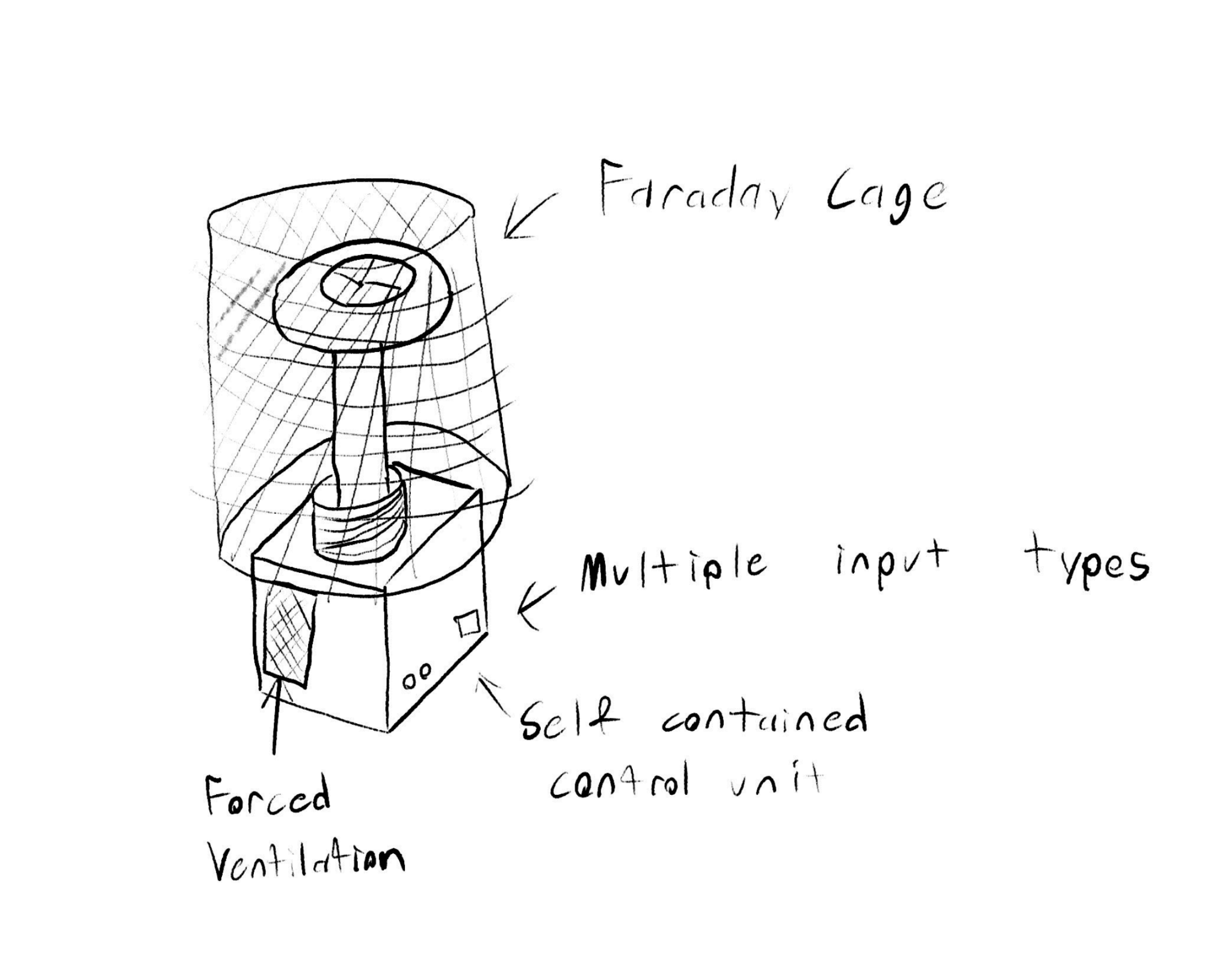
- Design a Faraday cage to enclose the secondary circuit
The following sketch is what an ideal final product may look like. The control unit has three subsystems, the digital controller, interrupter, and drive circuit.
Work Log 5 (2/18/2024 – 2/24/2024)
Accomplished this week:
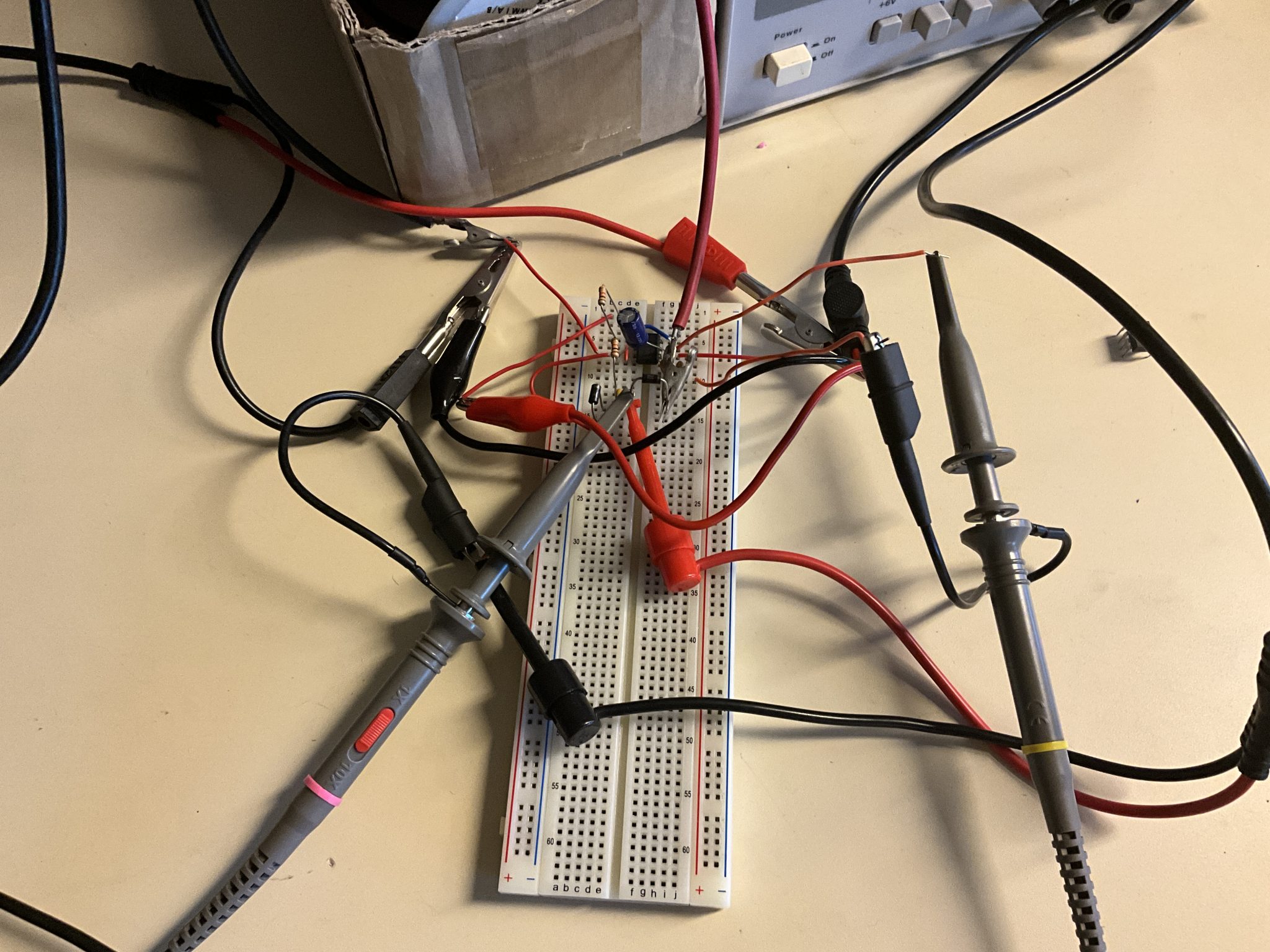
- Chose feedback topography
- Constructed prototype driver circuit
- Validated prototype driver circuit function using expected inputs
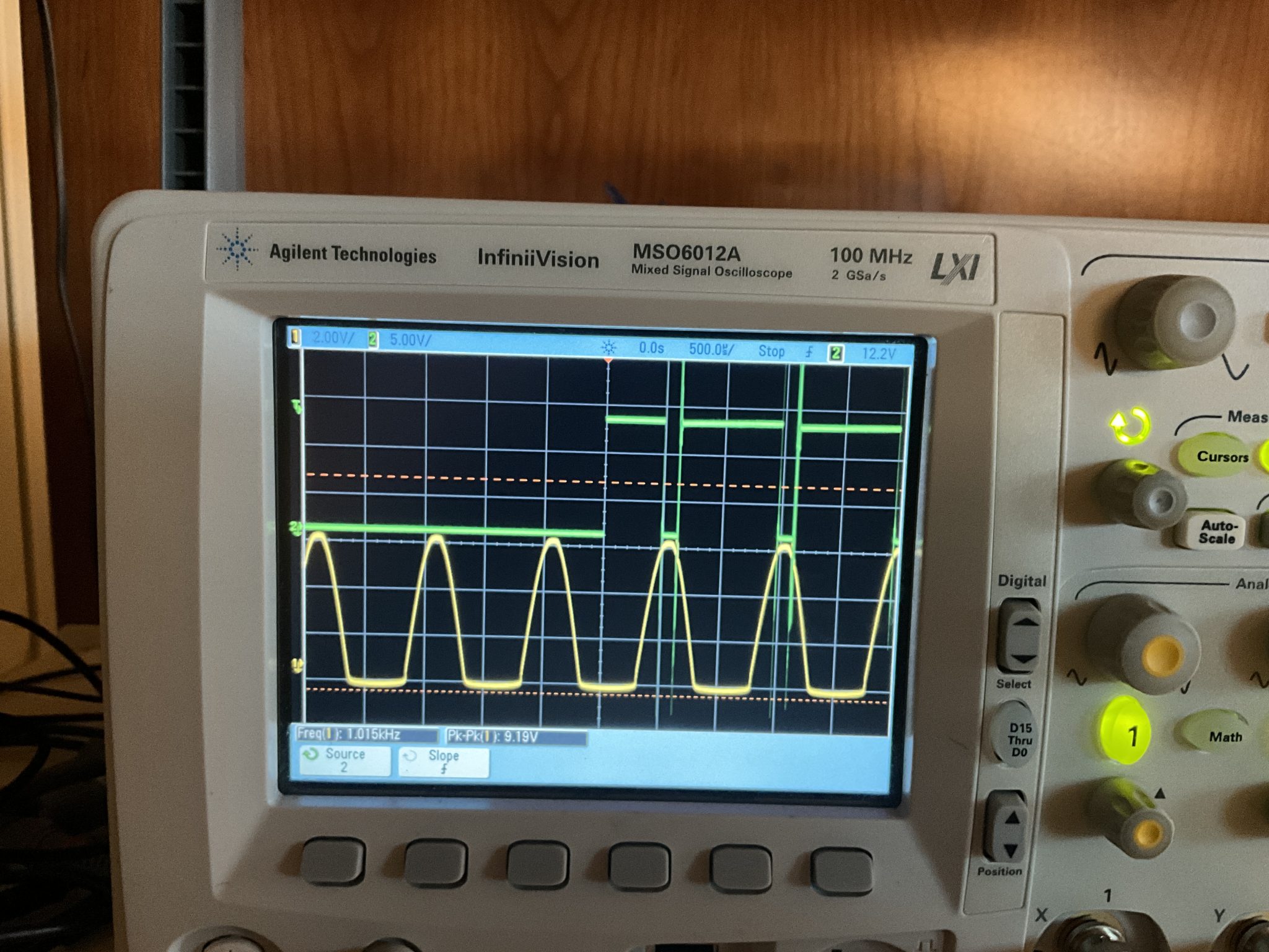
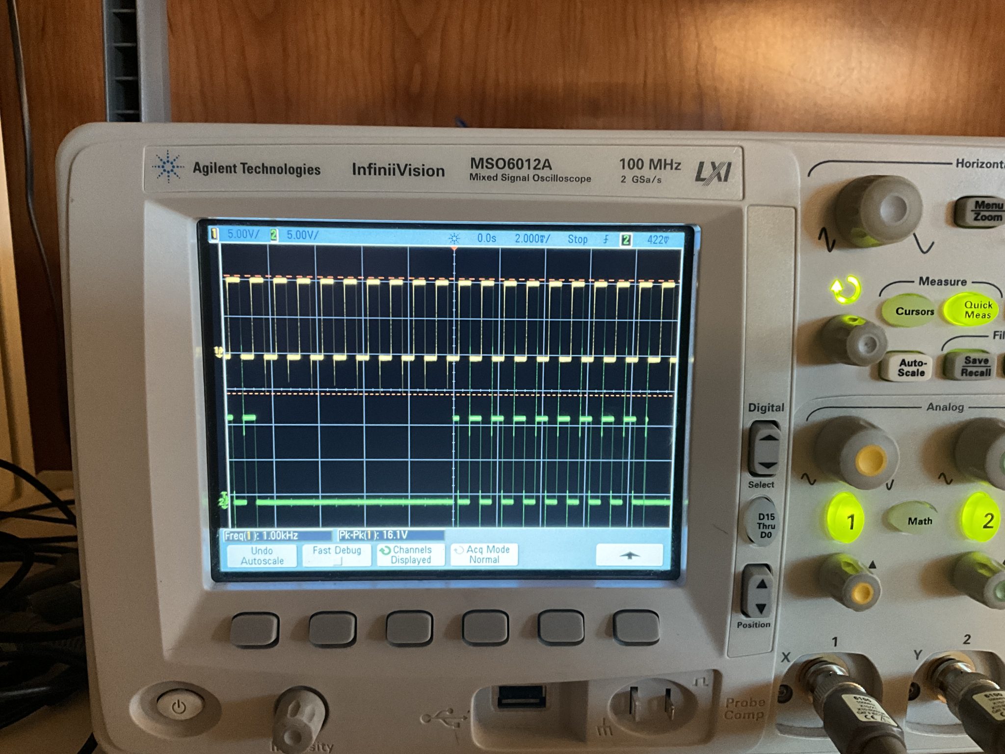
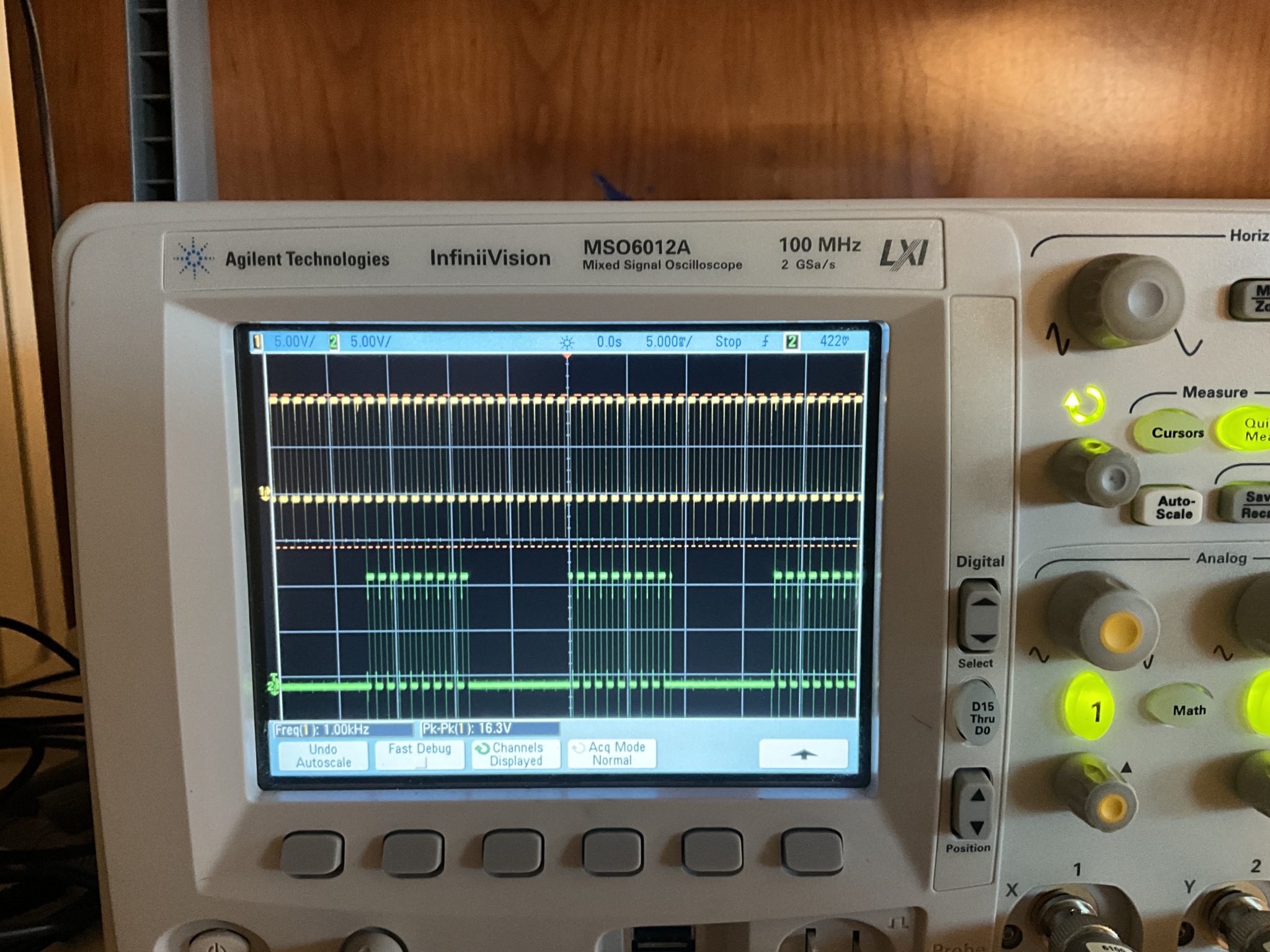
It was observed that a sinusoidal feedback signal causes the duty cycle of the resonating signal to stray significantly from 50%. As such, the final circuit will utilize two logic inverters in series in order to modify the sinusoid into a square wave of equal frequency (precise amplitude feedback is not necessary).
The images below detail the findings in the previous paragraph. The yellow signal is the simulated feedback from the Tesla coil, and the green signal is the output to the gate drive transformer.
Work Log 6 (3/3/2024 – 3/9/2024)
Accomplished this week:
- Determined method to have direct drive of the Tesla coil using an analog audio input.
Goals for this week:
- Prototype analog driver circuit in simulation.
- Construct physical circuit on a breadboard and validate with expected inputs.
Work Log 9 (3/24/2024 – 3/30/2024)
This week we attempted to connect the Arduino nano to the driver circuit, but we ran into a problem. I probed the enable pin of the driver circuit to make sure the voltage is compatible and found the enable pin to be at 12V. This would damage the nano as it can only handle VCC+-0.5V, where VCC is 5 volts in our circuit. As such, a logic-level converter will need to be added to the circuit. I believe this can done with a simple BJT circuit, since the enable pin only needs to be pulled down to ground, and will pull itself up to 12V. Developing this circuit will be the goal of next week.
Work Log 10 (3/31/2024 – 4/6/2024)
Some BJT’s in the lab were found to be appropriate for the logic-level converter application, so no new parts needed to be ordered. The circuit was prototyped with theoretical inputs and was found to be effective at pulling the enable pin of the driver circuit to ground without subjecting the input signal to high voltages. For next week, my goal is to combine this with the rest of the driver circuit on a prototype board to integrate it with the rest of the tesla coil systems.
Work Log 11 (4/7/2024 – 4/13/2024)
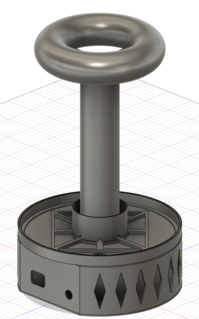
With final subsystem integration imminent, it was time to design and build the enclosure. Design of the enclosure was designed to use as many of the 3D printed parts we already had as possible to save time. Below is the final CAD render.
Work Log 12 (4/14/2024 – 4/27/2024)
This work log includes work from finals week as the project bled over. For the final week
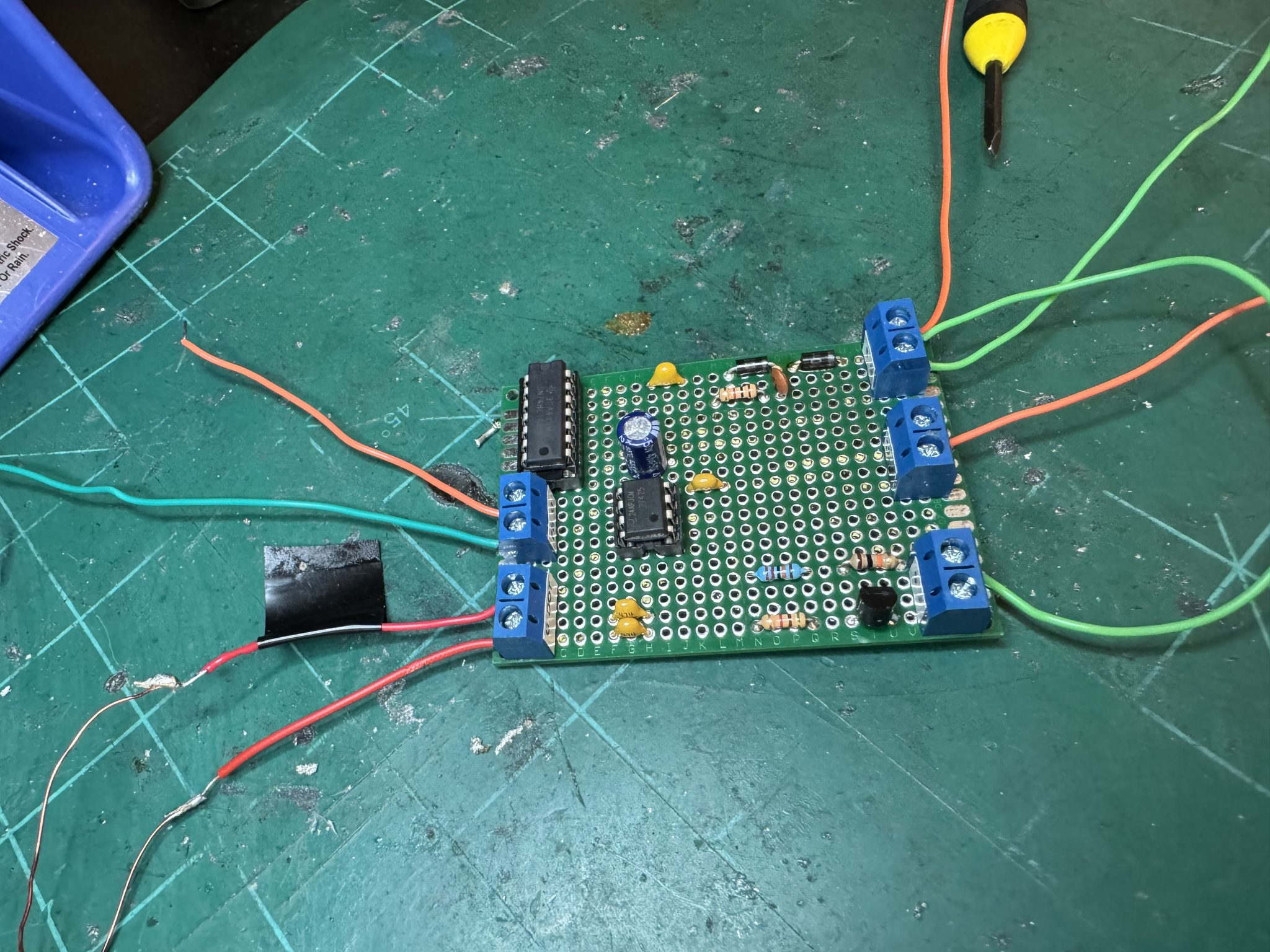
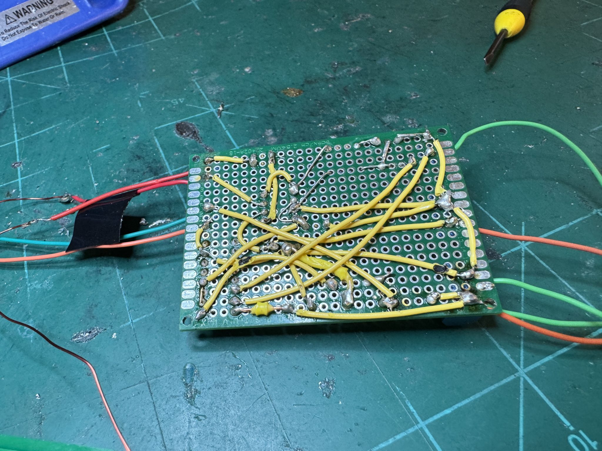
The breadboard driver circuit continues to operate as expected, but extra electrical noise and difficulty with form factor are sufficient reasons to justify moving the driver circuit to a Protoboard. Due to the relative complexity of the circuit, and the numerous modifications made from the base schematic, I decided to make a new schematic in KiCad for clarity. This also allowed me to find the optimal component layout for protoboard integration.
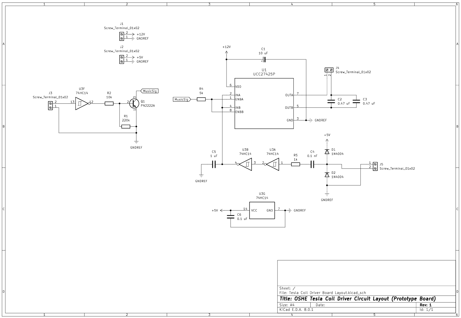
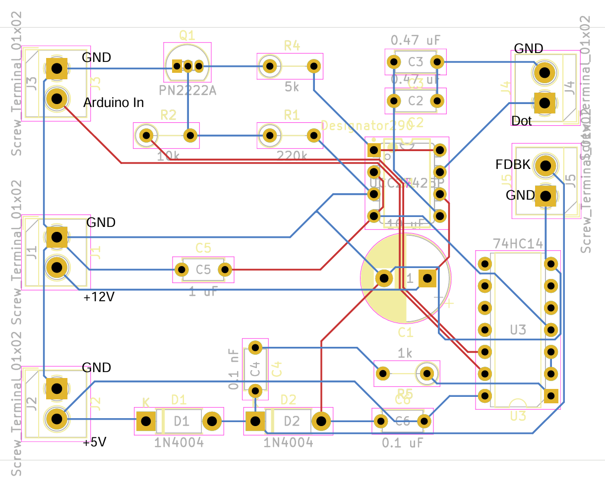
With these KiCad documents, soldering began. The resulting protoboard was verified similarly to the breadboard circuit, and all outputs worked as expected. One revision that was made was to invert the input logic signal so the Tesla Coil would be off when the Arduino is off, otherwise the Coil would be on all the time if the Arduino is disconnected. This inversion was achieved by using the extra inverters on the 74HC14 chip before feeding the signal to the PN2222A for amplification. The final board is below:
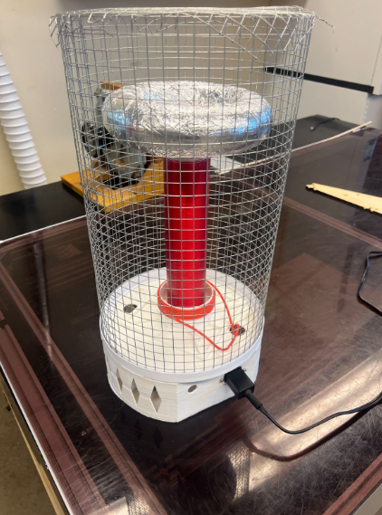
Finally, the Tesla coil was assembled with the printed parts from Work Log 11 and the other’s subsystems.
Tesla Coil (Fall 2023)
Work Log 1 (Week of 9/18/2023)
Over the past week, we have successfully determined the initial sizing for our secondary circuit. The bulk of the work has been on the sizing of components in order to maximize safety and audio reproduction characteristics. After the secondary circuit has been tuned, the values can be used to determine the tuning of the primary circuit to maximize the efficiency of the energy transfer. Parts have been ordered for the windings of the primary and secondary circuits.
Our main goal for the next week is to assemble and tune the secondary circuit ASAP, then we can choose components for the primary circuit.
Work Log 3 (Week of 10/23/2023)
I successfully acquired and scaled CAD files for the semiautomatic coil winding machine. Printing is ready to commence over the next week, and the secondary coil can finally be wound. This, combined with work in parallel on the driver circuity, will ensure we are making progress towards a functioning tesla coil.
Work Log 4 (Week of 10/30/2023)
Accomplished:
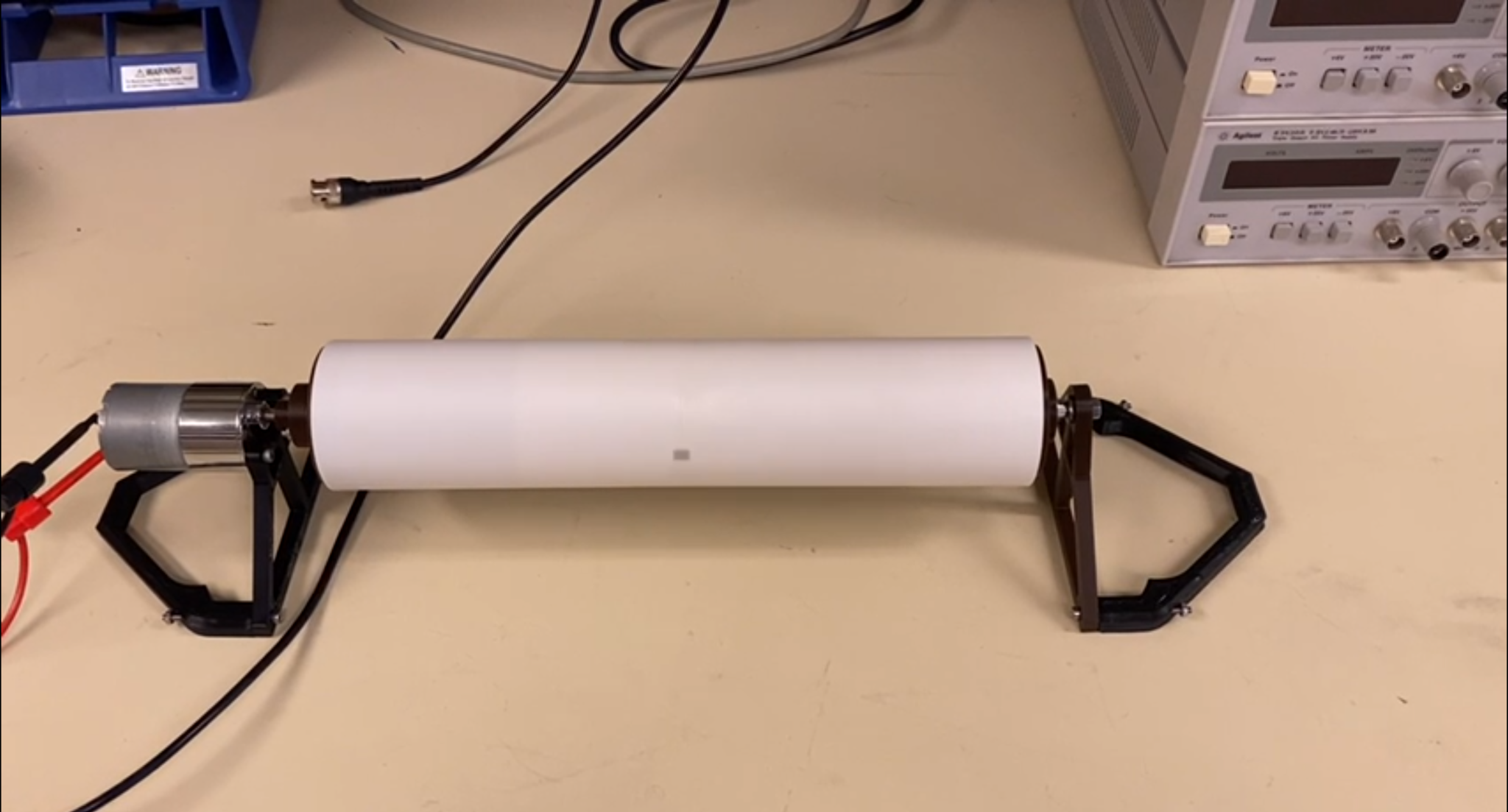
- Printed and assembled parts for semiautomatic coil winder (See attached image).
- Reviewed BOM for digikey order.
Immediate Goals:
- Wind secondary circuit inductor
- Assemble secondary circuit
- CAD frame for the primary circuit and attachment for the secondary circuit