
04/20/2025
This week Joel and I did out capstone presentations. The board is currently inoperable, we think due to the control board. I started creating a new one, but it is not done yet.
This coming week we will finish the report and I will finish soldering the new board.
04/13/2025
This week was mostly focused on documentation and the report. We have a rough draft of the report done.
We found an error in the battery code where we were not actually reading the lowest battery cell voltage. The battery cell voltages were in an array from 0 to 5, but a for loop was reading from 1 to 6. This meant that the battery cell voltages were getting ignored for some random value that just happened to be there.
This week I will be working on fleshing out the assembly instruction, updating pictures, and making sure all the electrical documentation and PCB designs look good.
04/06/2025
This week was focused on getting into the lab and putting everything together. Several changes were made to the perf-board design, such as the removal of the 5V regulator. For some reason it kills ESPs instead on powering them. Initially we thought it was because of a large (~25V) transient when first powered however, even after reducing this to within 5V using an input filter, it still killed an ESP. We decided to use the 5V output from the VESC instead. Unfortunately, this means there is less of a robust shutoff circuit, however it is functional.
The board is working now though. Future efforts will be focused mainly on documentation and the report.
03/30/2025
This week I designed and soldered a perf-board for the cell voltage monitoring and got the code working. It is now reading within 0.1V of the actual cell voltage. It also allows for battery charging and will soon allow for CAN communication.
This coming week we will finish everything else that we can. We have sign-off on Thursday.
03/23/2025
This week was focused on getting the battery protection system and monitoring working. They are not yet but there have been some major changes in our strategy. We are focusing on adding batteries in series. This means that we need to pay extra attention to load balancing of the cells. We are still going to bypass the BMS for discharge because we want more than 20A. We are now trying to measure the individual cell voltages. Our measurement is largely following this guide. I have physically altered the battery cable so that we can measure the voltages.
This coming week I will get the software portion working.
03/09/2025
This week I redesigned the precious circuit because there were some issues with it. It now requires a 5V reference voltage. Another team member is working on a 5V rectifier, so that will be used to supply the voltage.
This coming week, I need to work on the MOSFET design. The output voltage will lead into the gate of a MOSFET. One potential issue is the heat generated from the MOSFETs. We are also considering a solid sate relay instead of the MOSFETs.
02/16/2025
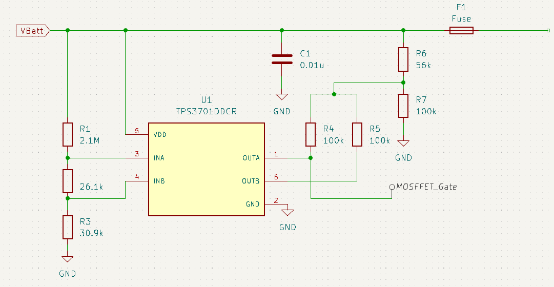
This week I worked on the design for the under-voltage protection system (seen below). Unfortunately, I did not design the right half of the circuit correctly because I was in a rush. I will be fixing it next week. The output of this circuit will be connected to the gate of two MOSFETs in parallel in order to switch the battery bus off in an under-voltage event. We chose to use this IC and analog components because they will be able to act instantly and restart when voltage is restored, unlike a micro-controller based system.
A fuse was added to secure against any severe over-current events. They should not happen as the current should be regulated by the VESC however we want to protect our battery and other components just in case some sort of severe fault happens. The fuse is a SMD component, but that is okay because it is unlikely to ever trip and is still possible to be hand soldered.
9/29/2024
This week was still focused on planning. On the battery module team we have decided on this 6S2P Li-ion pack. We selected Li-ion batteries because of their high energy density and our limited area. We chose the 6S2P configuration because it has a nominal voltage of 21.6V and a maximum current of 90A giving a maximum output of 1,944W. This will be plenty for a single-motor drive. We have decided to go with a pre-built pack because it makes the project more accessible and it helps us hedge our risk of damaging cells in construction. We do not have the budget to make that kind of mistake. It also includes a BMS.
Because this simplifies our approach so drastically the battery module team will now be responsible for power distribution across the board. We will have battery voltage “rails” throughout the board as well as supplying lower voltage to the control module. The battery voltage “rails” will allow additional battery modules to be added if the user chooses. They must be able to accommodate the anticipated maximum power. The ESC we are planning to use can accommodate 8-36V and 100A continuous or 300A instantaneous so the rails will be fairly beefy. I need to research the limitations of wire using DC power but I suspect we will be using 12-gauge as that is what the ESC uses so it doesn’t make sense to go larger than that.
We also are looking into how to regulate the battery voltage down to the lower voltage. The challenge is that the voltage from the battery will not be constant as it charges and discharges. We are looking at this buck converter for inspiration. It is capable of outputting 5V 1A. Initially we were planning to use an Arduino nano for the control module but have since changed to an esp32 based board that requires a higher input voltage of around 7-12V but operates around 3.3V. We are also planning to add other sensors (TBD) to the board so we may need a higher current as well.
The drive module has decided to go with an off-the-shelf ESC because of cost and accessibility reasons. It is based on the open source VESC project so it is extremely configurable and can be connected directly to a controller, bypassing the control slice. It supports many optional features and a wide voltage input range.
Not much progress has been made on the mechanical design. I got busy with an exam and working on planning for other modules.
For this coming week:
- Get mechanical design improved for printing before CDR
- Begin printing at least two module pieces before CDR
- Purchase threaded metal supports for CDR
- Learn about VESC both hardware and software in order to better understand how to implement the ESC.
- Determine what input voltage and current are needed for the drive module, design buck converter (or find one), and order parts.
9/22/2024
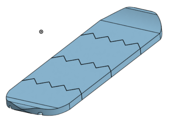
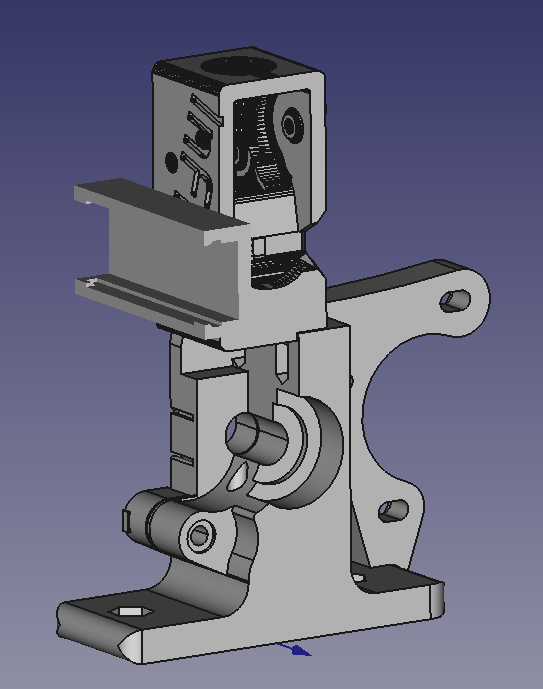
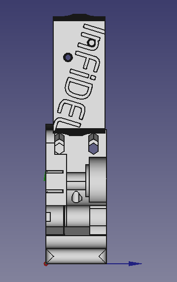
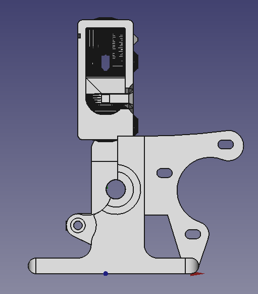
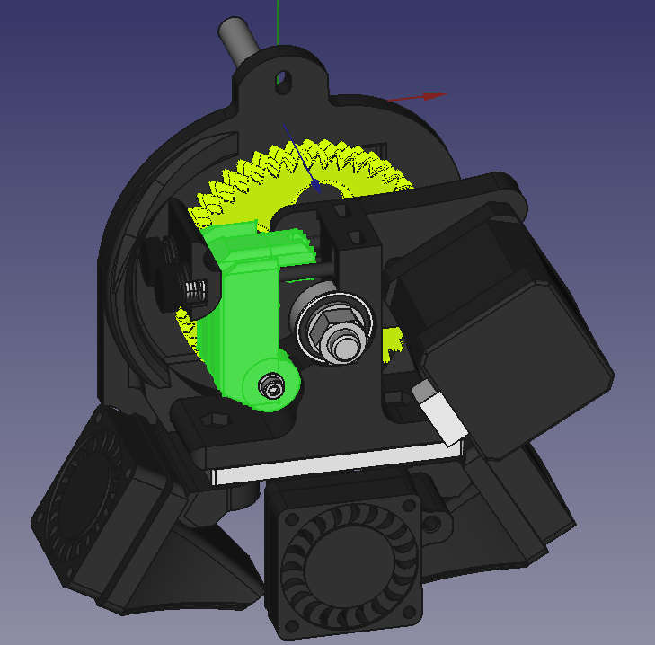
This week I worked on planning and component concepts. I created the first CAD draft for the mechanical design of the board (see below). It needs to be re-created using parametric design concepts as it was just a quick visualization for our presentation.
We (the battery slice team) decided that we will order a pre-built battery as it comes with a BMS and removes the risk of damaging battery cells in the construction process. It will be more expensive than if we made no mistakes during construction but we have decided this certainty is worth the cost. It also allows us to focus more on other aspects. The battery team will focus more on the cable harness for data and power through the entire board. We want to have a battery bus so that additional modules can be more easily added.
To do this week
- Determine and order specific components for the battery and drive slices
- Continue planning the project direction and meetings with Joel
- Update the CAD model to incorporate “woodwork” type designs to interlock the slices. This will allow the slices to be supported in both the horizontal and vertical directions, unlike the previous design.
4/20/2024
This week when testing the board we found some fatal shorts that cannot be easily fixed because the solder was trapped on the back of the board under one of the terminals. It was easier to construct a new board. Logan was in charge of that. When testing with the new board, a few minor errors were found, but we have not had time to fully test it yet.
Next week we will continue testing and correcting errors as much as possible. The goal is shifting to being as complete as possible for evaluation. We cannot currently get the stepper to move.
4/13/2024
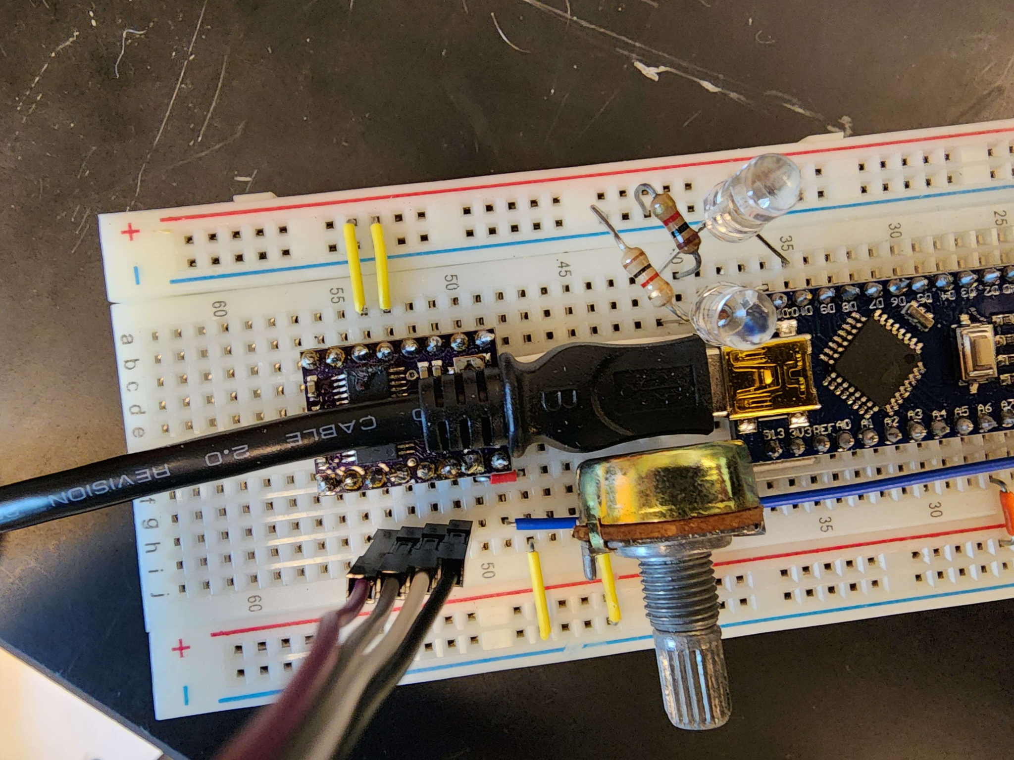
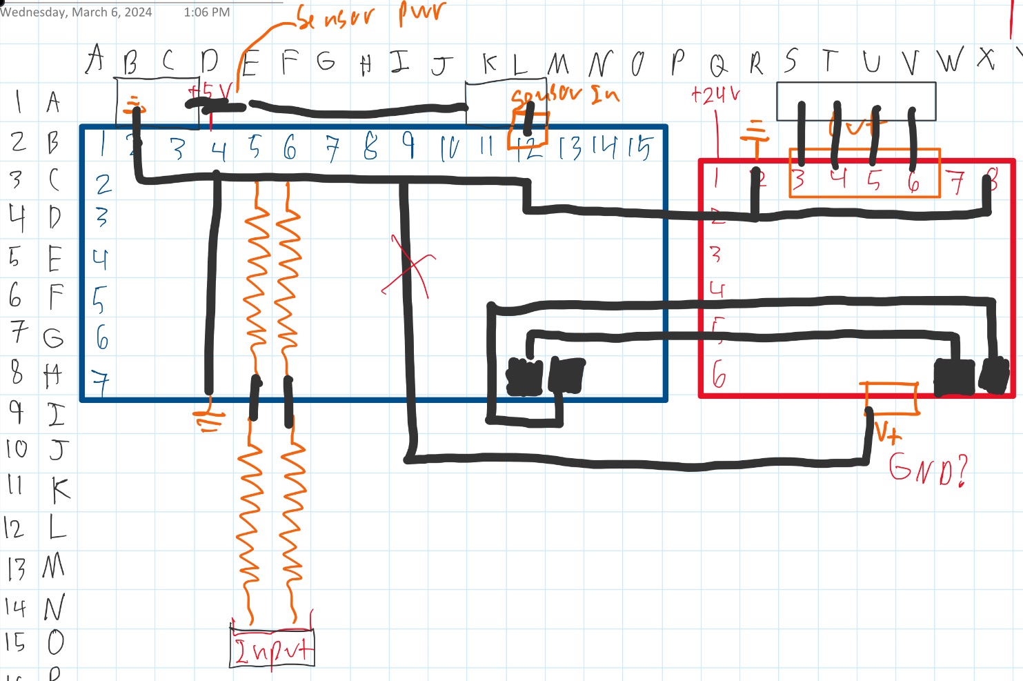
This week I found and corrected another error on the board where there were not enough ground ports for the sensor to be connected (picture 1). I helped verify that we have the wires correctly attached both into and out of the board. Initial tests with no power connected did not show any major problems. We are not completely sure what output goes where for the motor though. We will need to experiment to ensure correct connections. We have tested some on the breadboard and will use that as a starting point (picture 2).
This week we will begin integration tests and solve issues that come up. I will also need to find a better power source for the arduino.
4/6/2024
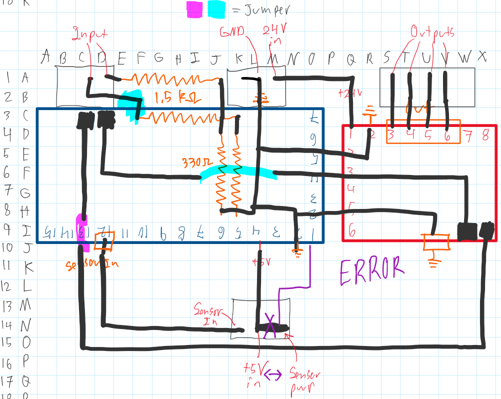
This week and last week I soldered the perf board. It took longer than expected because I hadn’t used perf board before and because I made a couple shorts and we did not have solder wick to easily remove the excess solder. I discovered an error in the perf board design (shown in drawing below).
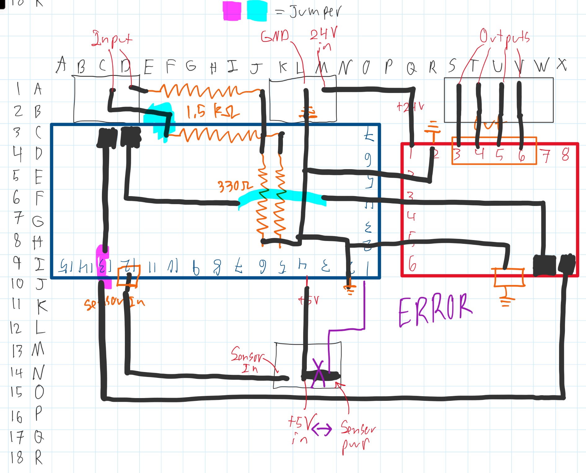
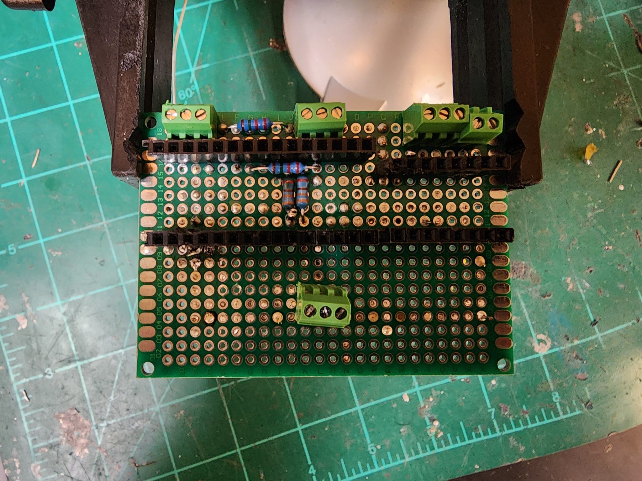
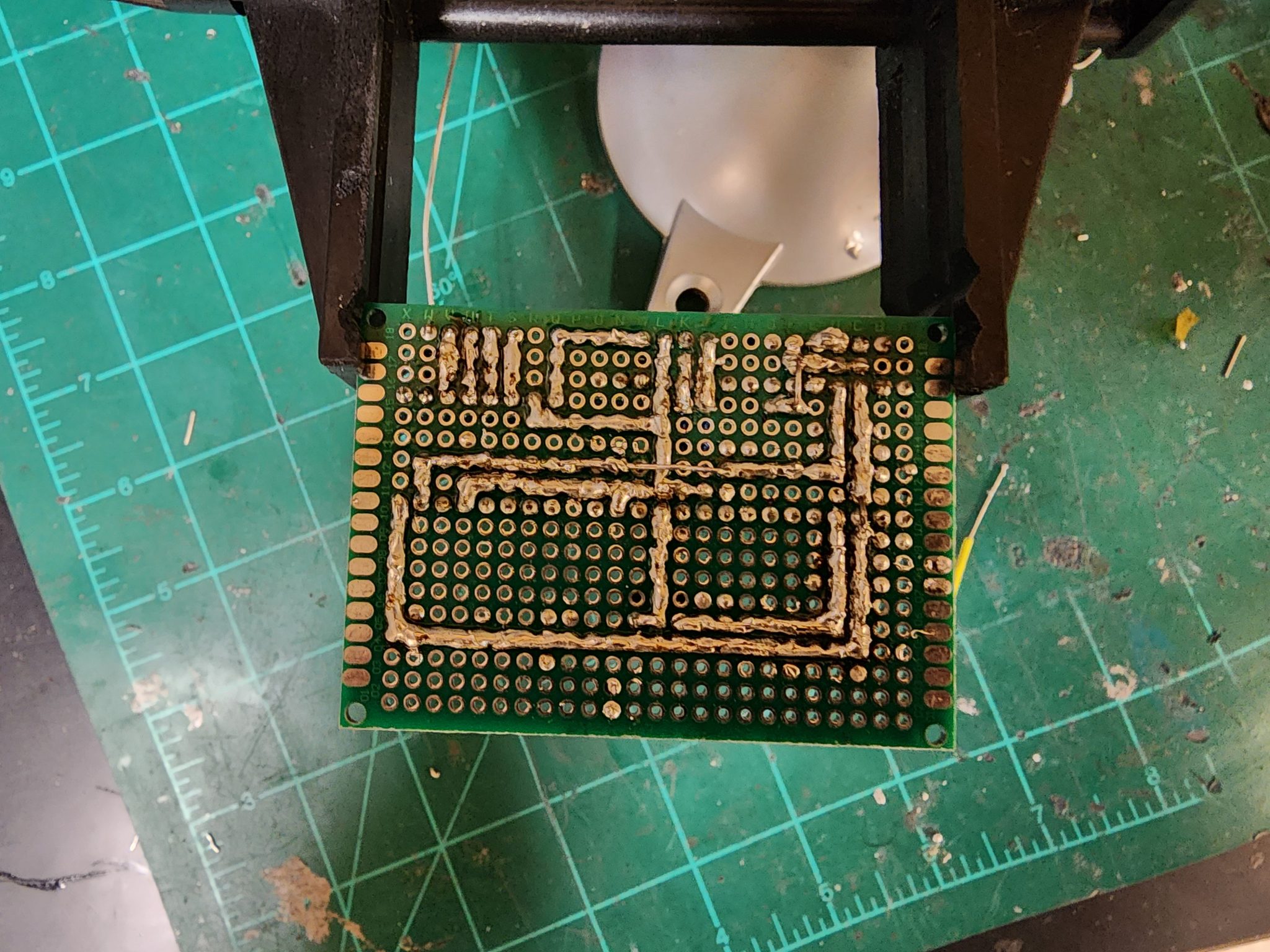
Next week I will fix the error and we will start testing the code/hardware integration. I cannot be more specific as I am not sure what problems will come up, although there will likely be many.
3/30/2024
I redesigned the schematic because the Arduino had to face the other way for USB access. I was constrained by the fact that I had begun soldering before I realized the error.
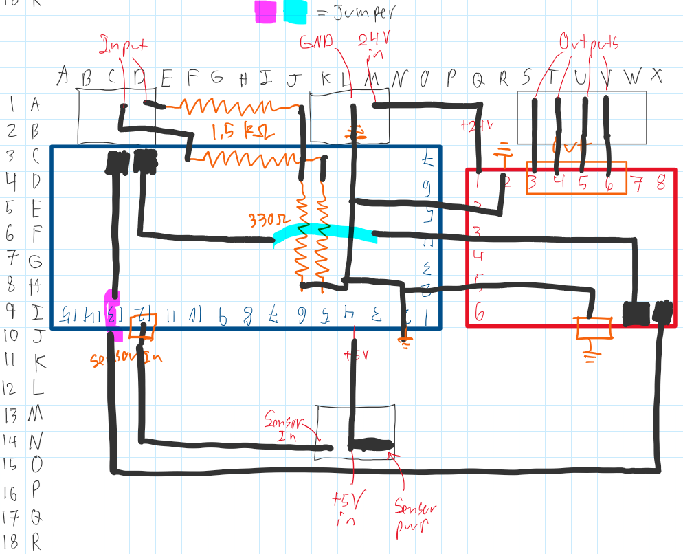
This week I will finish soldering the new design and begin testing testing with the electronics all on the printer.
3/16/2024
I converted the circuit schematic to fit on a perf board. There was a discrepancy between the breadboard and schematic. On the “bottom” of the stepper driver is connected to ground in the schematic, but was connected to V+ on the breadboard. We will test it both ways to determine which is correct. I did not build the board because we do not currently have the sockets to hold the Arduino and stepper driver. Those will be ordered this week. We may be able to scavenge some from a previously used board.
This week I plan to do the following
- Salvage standoffs and build perf board
- Begin testing electronics in the assembly
- I will order the required standoffs
- Finish designing PCB
2/10/2024
This week was less productive because of Winter Carnival. I found information and electrical schematics in older documentation (here). The reason there are two stepper drivers is because one is used for simulating the input from the printer. It does not need to be included in the actual assembly.
This week I plan to do the following:
- Design a PCB from the schematics to determine the required size of PCB. This will help the mechanical design.
- I am not completely sure what else I will do this week. Our team meeting was interrupted by Winter Carnival last week.
2/3/2024
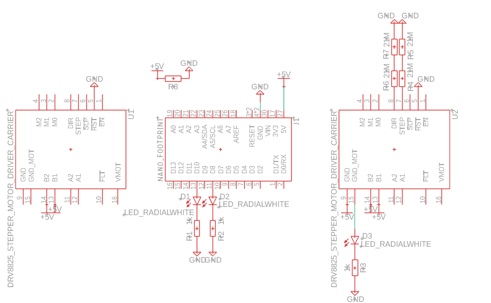
This week I worked on creating a circuit diagram for our circuit using Fusion 360. I downloaded the layout of the Pololu DRV8825 Carrier that we are using from here and the Arduino Nano from here. As I was creating the diagram, I became less confident that these are the correct models (the pins don’t make sense) and I may have to create the layout myself. The current iteration of the diagram is below. I have not yet connected everything together because the proportions of the stepper drivers and the Arduino Nano seemed wrong. The stepper drivers should be significantly smaller than the Arduino Nano.
This week I plan to work on the following:
- Ensure all components and schematics are accurate.
- Fix or remodel any that are not.
- Connect the schematic together.
- Add the hall effect sensor into the model.
- Start designing a PCB so that we can also begin designing the hardware to hold it.
1/27/2024
This week I have reacquainted myself with the project as well as learning more about the electrical layout of the project. I am trying to figure out why two motor controllers are on the breadboard when we are only using one motor.
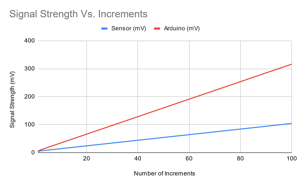
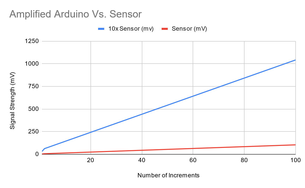
We have discussed a few possibilities to help resolve the noise problem. One possible issue is a mismatch in the sensitivity of the sensor and the arduino. They may have different increments meaning that sometimes an increment from the sensor will be “skipped” by the arduino. According to its datasheet, the sensor has a typical sensitivity of 3.125 mV/Gauss. We think the arduino has a sensitivity of 4.883 mV (5V/1024 increments), but we aren’t completely sure yet. Because the sensitivities are not quite matched, the difference adds up over time. This is demonstrated in the graph below. One potential solution is using an amplifier to increase the signal strength of the sensor so that every time a value is “skipped” it is less significant. This is also shown below. I used 10x amplification to illustrate the point. We will probably not use that much.
I envision the project to look something like this by the end of the semester:
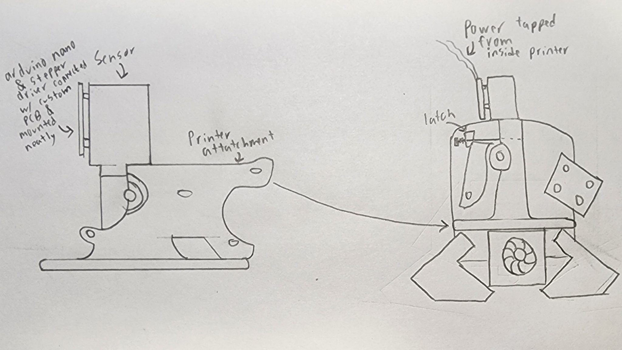
The dimensions are not quite how I imagine them – I’m not an artist, but the idea is still there.
Next week I plan to do the following:
- Create an electrical schematic of the project.
- I will design a PCB to connect everything when the design is more finalized.
- Look into if using an amplifier will work (voltage range of arduino and sensor) and alternative methods to accomplish the same idea.
- Identify voltage range the arduino can handle.
- Identify maximum safe amplification.
- Look into alternative options.
- If everything looks okay, then design an op-amp circuit for the correct amplification.
- Identify voltage range the arduino can handle.
Spring 2024
10/28/23 – 11/4/23
I have decided to use this holder to attach the arduino nano to the sensor, at least for now. I don’t love its position very much, but it’s the best place I could find.
Next week I will begin 3D printing it so that we can continue to a more integrated test.
10/21/23 – 10/28
This week I have been working more on the mounting mechanism (pictures below). The problem that has taken up most of my time has been trying to add holes for mounting. I imported the sensor block as an STL file, so the software doesn’t consider it an “object.” This makes removing material from it much harder. I have a few ideas to work around this if I cannot find a solution soon.
- Add a “holder” onto the design, making it more complex and bulky.
- Add material to where the holes should go as a guide to make the holes with other tools after printing. This risks breaking it in other ways though.
- Remake the entire sensor body in my CAD software so that I can have the part file required to add the holes to it. I am not inclined to take this route as it will take much longer than the others.
9/30/23 – 10/7/23
I have been working on a way to mount the sensor and other electronics to the 3D printer. My plan is to modify the sensor housing. I will add mounting holes for the electronics. I also plan to attach it to the “idler” by printing a new part with both combined into one. Most of my time this week has been spent learning to use FreeCAD.
9/17/23 – 9/23/23
Researched the power source specifications and extruder wiring diagrams of the Lulzbot Taz 6 to determine where we can tap power from and how to intercept the signal from the extruder stepper.
The power can come directly from the power source as it is 24V, which is what we are using for our electronics.
The extruder pin-out was found from the open source documentation here. Intercepting at this connector seems easiest because we can take the motor pins and let all other signals pass. We can then send our new signal directly to the motor. From a wiring diagram and a BOM I found the connector housing used in the 3D printer. The wires appear to be 22 awg, so they would use a female connector like this and a male connector like this.