
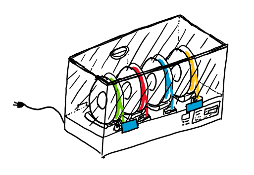
Filament Flip-Flop:
4/14/25 – 4/18/25
This is the last week of the project. I made a custom profile for using FFF through the Orca slicer. This slicer provides a better experience for making multi material prints. This week I presented my capstone presentation to show my contributions to the project. This presentation went well other than going over the allotted time. FFF is now a functional system but lacks the reliability needed for being used. I’ll continue working on this project in my own time and in the future I’ll release the updated reliable setup. The report for the project is now mostly complete. It walks through all the instructions for creating FFF and slicing a print for it.
4/7/25 – 4/11/25
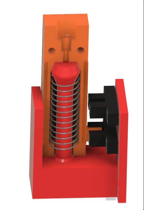
This week we worked on the reliability of FFF. Nick was able to make a service routine on the Raspberry Pi that could now auto start the main python script. I’ve redesigned the buffer for a range of other springs that are stronger. We found that our stepper motors were now the weak point. We now tuned the steppers to their max current to provide the most torque. This brought it closer to being able to compress the new springs, but would still fail sometimes. With the springs we had, there is not one at the correct spring constant for just enough force. We might be able to change steppers to 40-60 steppers that could compress the overkill springs. But we would not have these new steppers in before the semester ends. I plan to test this with the machine I’ll be building for my own printers.
3/31/25 – 4/4/25
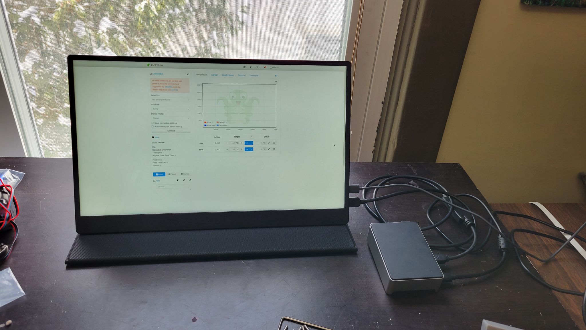
This week, FFF was reviewed for its functional requirements. FFF achieved all of its requirements but still needs some refinement. There are some areas that need tuning to operate better. Currently, we have Cura setup as a compatible slicer for FFF. While it is well tuned for our test printer creating great quality prints, it is difficult to modify 3d models to be multi material. Another issue is the reliability of engaging a new filament roll on the printer side. Our buffer system applies pressure onto the extruder of the 3d printer to help start its feeding. Our test printer requires a large amount of pressure due to being designed to have its release pressed when loading filament. Sometimes, our buffer doesn’t apply enough pressure at a filament change, causing the printer to not grab it and therefore not print, failing the print. Last, the python script that controls FFF’s function is not auto starting through the auto run methods we implemented. This is minor as the script can simply be ran when you turn on FFF.
3/24/25 – 3/28/25
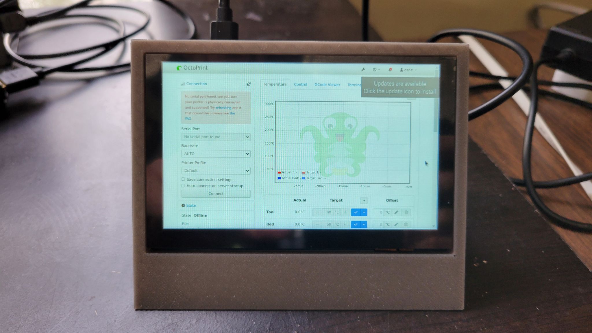
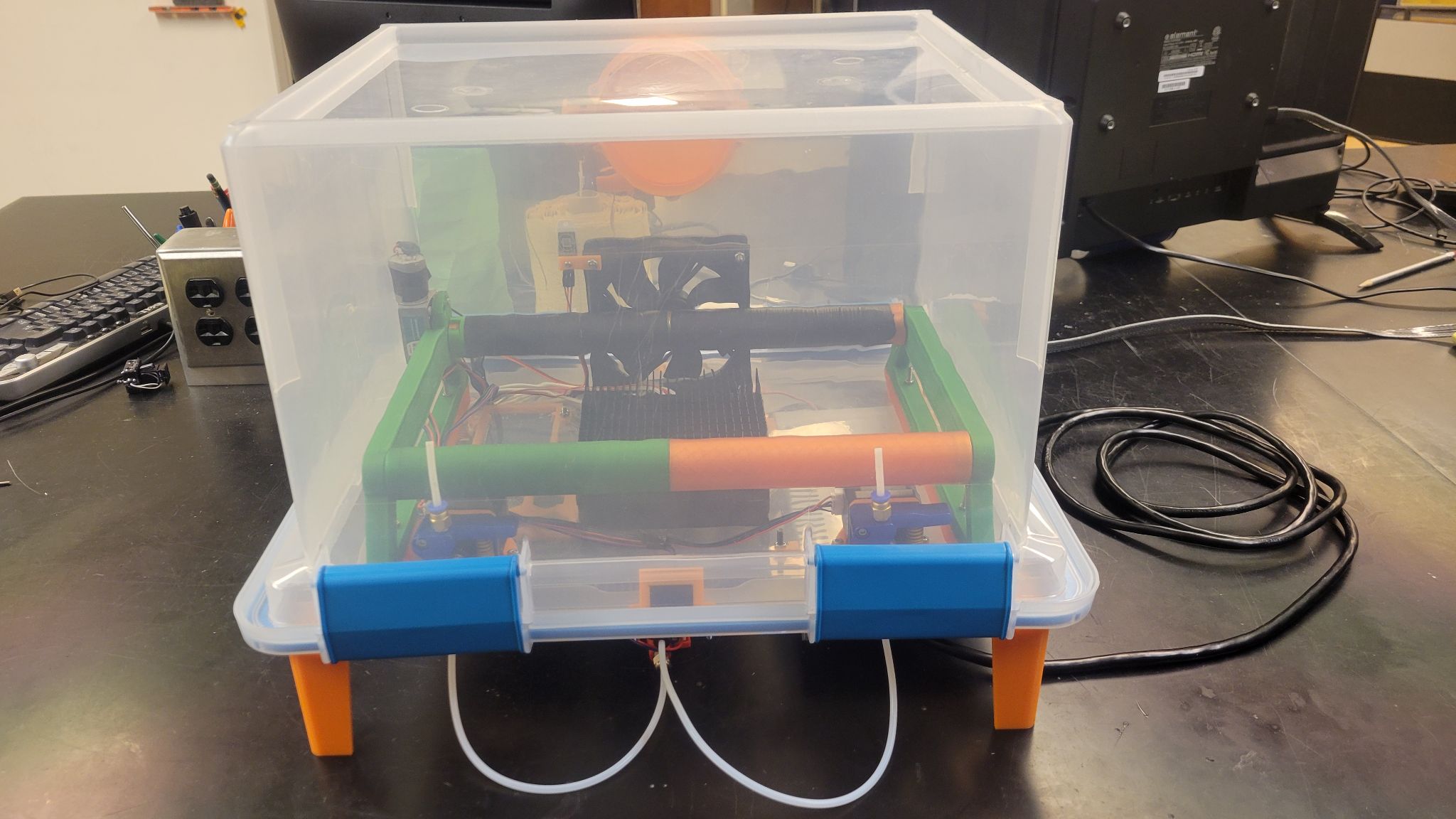
Octoprint interacts with FFF through the changing of a json file’s values. These values are changed through the use of the Octoprint plugin GCODE System Commands. This uses custom gcode to run terminal commands that update the json file. I added an easy touch interface for this with another plugin OctoPrint-TerminalCommands. Where I added buttons that run these custom gcode commands. The new box design has been printed and all the parts have been assembled. We are starting print testing for the machine.
3/17/25 – 3/21/25
After testing some code with help from the creator of Telemetrix, I was unable to determine the source of the error stopping the use of 3 steppers. With this issue I determined to return to the old Arduino code. With this the python on the Raspberry Pi changed from Telemetrix communication to a simple serial connection. The old Arduino code from last semester had some issues with multi-tasking that I researched ways to overcome. I found that using time intervals to control different aspects and removing print statements drastically reduced the loop time for running the stepper motors and heater. This gave more reliable control and better performance from the steppers. This next week I will be working on the integration of our parts with Octoprint and the physical assembly.
3/10/25 – 3/14/25
I’ve gotten movement from the stepper motors. I was able to create 2 stepper motor objects that are connected to the correct pins and can move when I send the main script into a state the request for filament. I then went to expand to 4 steppers but found a strange reaction. Once I add the 3rd stepper, I can’t get any stepper to mover other than the first stepper declared. I’ve tested each stepper by swaping out the pin assignments in code, and determined there are no electrical issues. Though, there is an error in the code. I’ve read through the github issues with telemetrix and found 2 similar problems. The first was someone looking to run 5 steppers. This was simply a set hard cap that was then updated to 8. The other had an issue where creating a 4th stepper object broke the other steppers. The issue was found to be that the Arduino uno did not have enough memory to have 4 stepper objects after additional features were released for the telemetrix4Arduino. I’ve tested to see if there were my issues, but found they were not. I have found an alternative that may solve my issue by deleting and recreating stepper objects so that I only have one stepper declared at a time. I plan to implement this and work on the other outputs needed for FFF.
3/3/25 – 3/7/25
I have worked more on the python code to implement telemetrix. I’ve created code that can change the requested filament and have the main script react to it. This was done by having a json file that is manipulated by other programs to update the state of the main script when it loops back to check for any changes. Motors for the filament rollers have been ordered. This next week I will be working on the code and helping with any CAD adjustments that are needed.
2/17/25 – 2/28/25
Parts have been ordered for the new heater. The new heater is 400W, this higher wattage should dramatically shorten the heat up time of the enclosure. We also ordered a PWM controlled AC dimmer that will give analog heating control. I’ve done testing with the firmata code, and decided to update to a newer protocol. Telemetrix is the newer version that supports more advanced control over stepper motors. I have found some issues with these protocols. Inputs are only communicated when a change happens at the input. This means when turning on the machine, we don’t know the states of the filament sensors until they change. I’ll continue working on the code this next week.
2/10/25 – 2/14/25
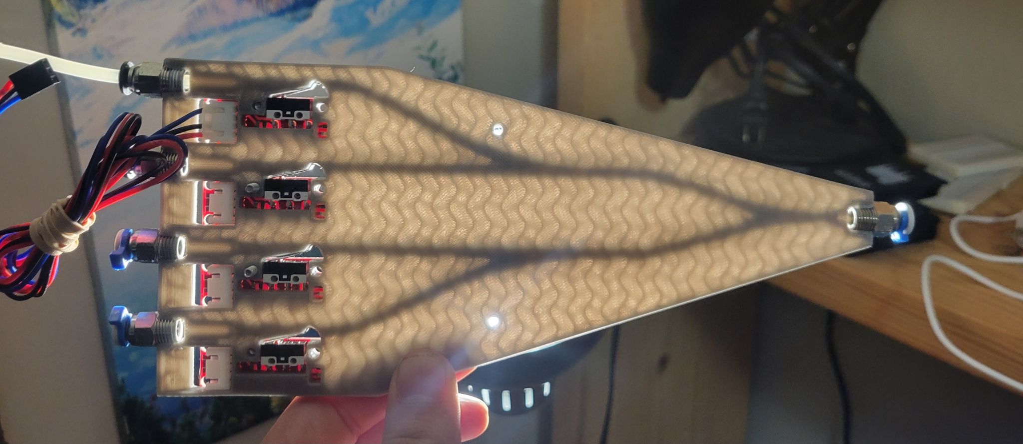
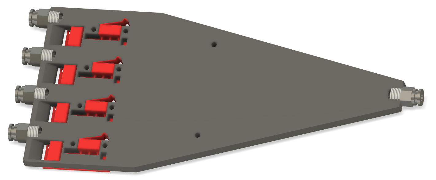
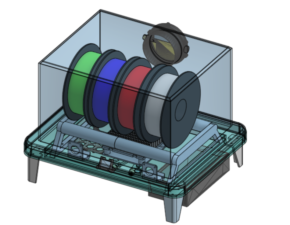
I’ve continued working on the y-splitter. It currently is on version 16. The has been optimized to be printed in a fraction of the time. Unlike the old design that would require over 10 hours of printing to support 4 rolls, the new design takes just 2 hours and operates smoothly. The team has started the reorganization of the electronics box. The prototype has suffered from a lack of wire management and was difficult to assemble. The new design in progress will have a better layout, reducing the lengths of wires going across the machine, and provide a better mounting system for better assembly. CDR presentations went well, and the team is on track for completing our goals. This next week, I’ll be working on prototyping code for the FirmataExpress python scrips.
2/3/25 – 2/7/25
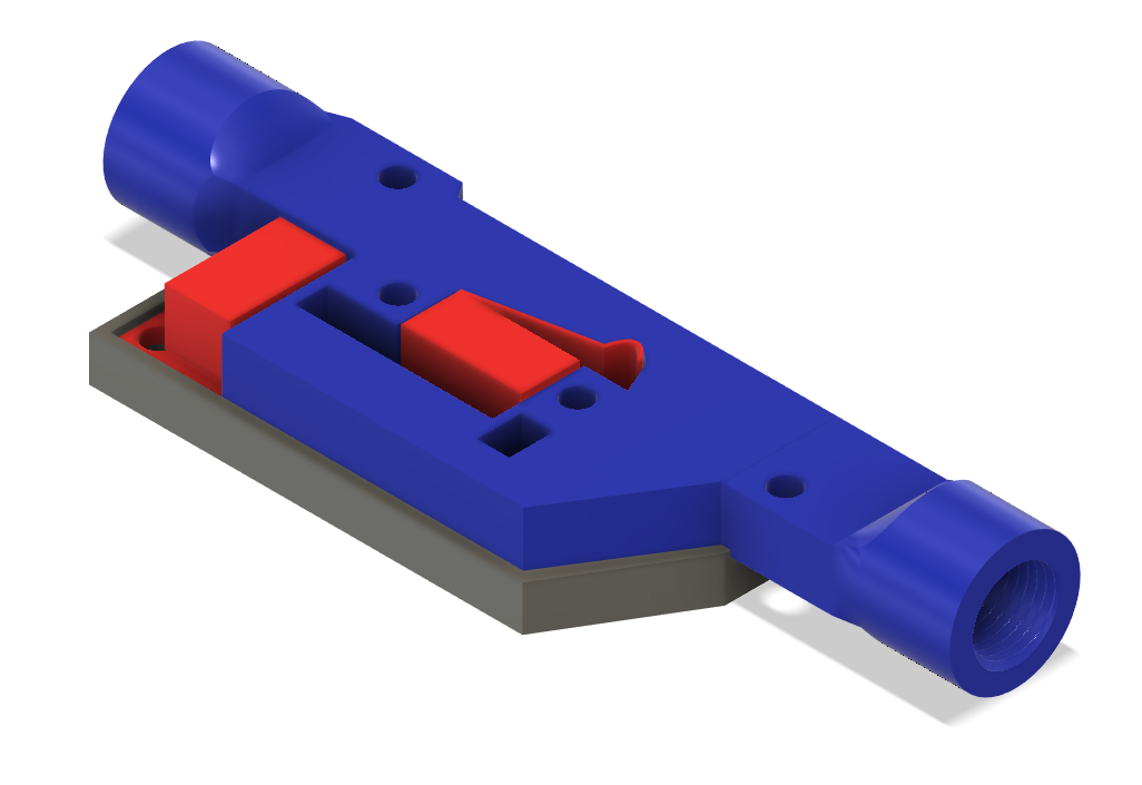
The parts for Proto-Dash where not delivered in time for the project. We were able to overcome this issue with similar parts I had on hand. These parts were oversized and ran on AC control, but we were able to to adjust our control scheme to accommodate these differences. We were able to get our system to be fully operational. With a working prototype, we created a video and documentation for the overall project. With Proto-Dash done, I resumed my work on FFF. The touch screen was delivered, and I designed a 3d printed mount and modified the Raspberry PI config file to get it operating. I also change the auto opening OctoPrint interface to be in kiosk mode to prevent popups and have the correct scale. I’ve started working on the new Bowden y-splitter. The new y-splitter has the filament sensors in the same part and supports 4 rolls. I’m testing different filament path tolerances to minimize friction in the part while still fitting on a standard Ender 3 bed(220mm x200mm). This next week I’ll continue working on the y-splitter and creating the team’s CDR presentation.
1/27/25 – 1/31/25
For the Firmata system I am using the FirmataExpress library that adds support for DHT sensors and stepper motors. This gives us the required commands to control the existing FFF prototype other than the small display. The display can be added back by connecting it directly to the raspberry pi. This week I worked mainly on my OSHE role task of participating in the Proto-Dash pilot run. Our task is to create an automated vertical garden system. Our first meeting was last week were we made a rough design and ordered parts. This week I worked on the CAD for this project and 3D printed the parts for it. Next week we’ll be finishing the Proto-Dash event. I plan to continue testing the Firmata code and start the CAD redesign on FFF’s Bowden tube system.
1/20/25 – 1/24/25
This week we presented the status of the project so far and our plans for the semester. Parts have been ordered for the extension to support 4 rolls, heater improvements, electrical consolidation, and a screen for Octoprint interaction. I am working on the code changes to overcome our previous issues with Arduino libraries. I am testing the use of Firmata to move the code to the Raspberry Pi to allow motors to move while other features continue running.
1/13/25 – 1/17/25
New designs for the filament holder have been made to give better filament rollback during retraction. With the new design, each filament roll has its own set of rollers and motor for rollback. The heater system is also getting overhauled to have a higher output for a quicker heat up of the enclosure. The electrical is being consolidated to a single power supply through the addition of buck converters. The electrical will also be getting a fused switch for safety and ease of turning the system on and off.
1/6/25 – 1/10/25
With the new semester the team has a new member. This week I showed him what the project is, its goal, and what we have so far. The team made a new spec sheet on the requirements needed to be completed this semester. With the new goals we started putting together a list of parts to order.
11/25/24 – 12/6/24
The new filament detectors works well with the new endstops. The optical endstops have been reused for the buffer to detect when it is full or empty. The buffer works great after its 3 iterations. The bowden path is completed. All the individual sections have been mounted into the enclosure and electronics mounted on the underside. The Raspberry Pi has 4 pins connected to the Arduino to communicate filament changes. The prototype is fully within our spec. There are many improvements to be made for next semester for faster heat up, supporting 4 rolls, and better code to work around library limitations.
11/11/24 – 11/22/24
The designed filament detectors turned out as a success. They are able to detect when filament is in the module. We did find a limitation of using an optical sensor. If you use transparent filament, it will not be detected. To add support for translucent filament, we need to use a normal endstop to detect the filament. I am working on this redesign to use Makerbot endstops. The y-splitter has also been made. Currently, the y-splitter is a 2-to-1 path as the prototype supports only 2 rolls. In the future it will be expanded to 4-to-1. I will also begin work on the buffer.
10/28/24 – 11/8/24
The rollers for the filament spools has been assembled. It is able to let the rolls free spin and get rolled back when the rollback motor is ran. A screen was added to the enclosure to display the enclosure environment information (air temp, humidity, and heater temp). The bowden path is being worked on for sensing and combining the filament paths. This requires the extruder motors, filament detectors, y-splitter, and buffer. The filament sensors are being made first. They are being designed to use optical endstops to detect the presence of filament.
10/14/24 – 10/25/24
We build the first prototype for the heater. We have a DHT22/AM2302 temperature & humidity sensor to monitor the enclosure’s conditions. There is also a thermistor on the heater to prevent it from overheating. Using these inputs we have the ramps board enabling and disabling the heater. Currently, the system can slowly bring up the temperature in the enclosure.
10/7/24 – 10/11/24
I worked on motor control through the Arduino and Ramps board. I used the AccelStepper library to control stepper movement. I was able to move the steppers and determine a good running speed for them. I did learn that a limitation of the AccelStepper library is that nothing else can run on the Arduino while moving the motors. We’ll need to implement safety considerations of not being able to monitor the rest of the system while moving motors. There is a good chance we will need to switch from this library for next semester.
9/30/24 – 10/4/24
The team decided to change directions on the software for the project. We will continue researching making our own plugin for Octoprint, but will be using an existing plugin that allows for g-code macros that run python programs. The idea is to have the g-code macros to run its matching python file to communicate filament selection and control of the FFF system. Feedback from the CDR has lead us to also choose to use an Arduino and Ramps 1.4 board for interfacing with motors and sensors.
9/23/24 – 9/27/24
This week I continued working on the Octoprint plugin. I am following Octoprint’s tutorial on creating a simple plugin. The plugins are written in Python. I am not familiar with Python, so I will be learning this new language. My goal for an initial prototype plugin is to have it communicate through a serial port to an Arduino like board. CAD for our project is being moved from working in Fusion 360 to Onshape as Fusion 360’s team CAD is not available to personal and student licenses. Our ordered parts have not arrived yet.
This next week is the CDR evaluation week. The team will be updating our slides for our presentation. We will continue working on the prototype CAD in Onshape. I will be working on my prototype plugin and checking in on when our parts arrive.
9/16/24 – 9/20/24
This week I created an instance of Octoprint on a raspberry pi. I setup the pi to boot into Linux Cinnamon desktop and auto open the web interface for Octoprint. I have started the creation of a plugin for Octoprint. The parts for the heater system and printer host controller were ordered this week. The forms for the ordered parts have been filled out. The team’s project presentation went great. There was feedback on concerns on how various slicing software could be used for initiating filament changes, and how printers could purge the previous filament for priming the new roll.
This next week I will continue working on the plugin development and work on our CAD design. When our new parts arrive, I’ll move the Octoprint instance from my personal raspberry pi to the team’s new pi. I’ll also help the sub teams to start prototyping the filament dryer control.
9/9/24 – 9/13/24
This week, my team finalized our project specification and researched parts to order. Our list of parts are being logged into a spreadsheet to track our spending, if parts are ordered, and if the parts have been received.
This next week I will be working a rough CAD model, ordering parts, setting up an instance of Octoprint on a raspberry PI, and researching Octoprint plugin development. I will also be helping my team make a short project presentation for the next enterprise meeting.
BREAD BUNS:
4/15/24 – 4/19/24
This week I reformatted my code to better explain why each line is used. Additional testing was done this week for the communication from the Arduinos to the raspberry pi. Small adjustments were required for the information to be write the scanned info into the server. I also helped other teams 3d print some parts and debug why a laser was no longer operating. This next week I will be setting up a demonstration of the working hardware.
4/8/24 – 4/12/24
This week I got the receiver to display to the screen and send the scan information to the raspberry pi. The scanner is no longer limited to the size of the buffer for the max characters in a barcode or QR code. The code communicates an end of transmission that lets multiple uses of the buffer join for the entire transmission. I was unable to solve the USB scanner having a linking error. This next week I will research more into this error. I will also be recommitting my Arduino code and and ensure my documentation is precise as this semester comes to a close.
4/1/24 – 4/5/24
This week I got all the scanned characters to print onto the scanner’s screen. The usb scanner is currently not communicating to the usb to serial module. There is nothing sent over the uart communication when the scanner scans a barcode. When the scanner scan a barcode, it beeps 3 times vs the normal 1 beep. The documentation I can find on these error codes says the 3 beeps mean the scanner is not linking. This next week I will be researching how to link the usb scanner and I will be adding a display to the receiver/slice.
3/25/24 – 3/29/24
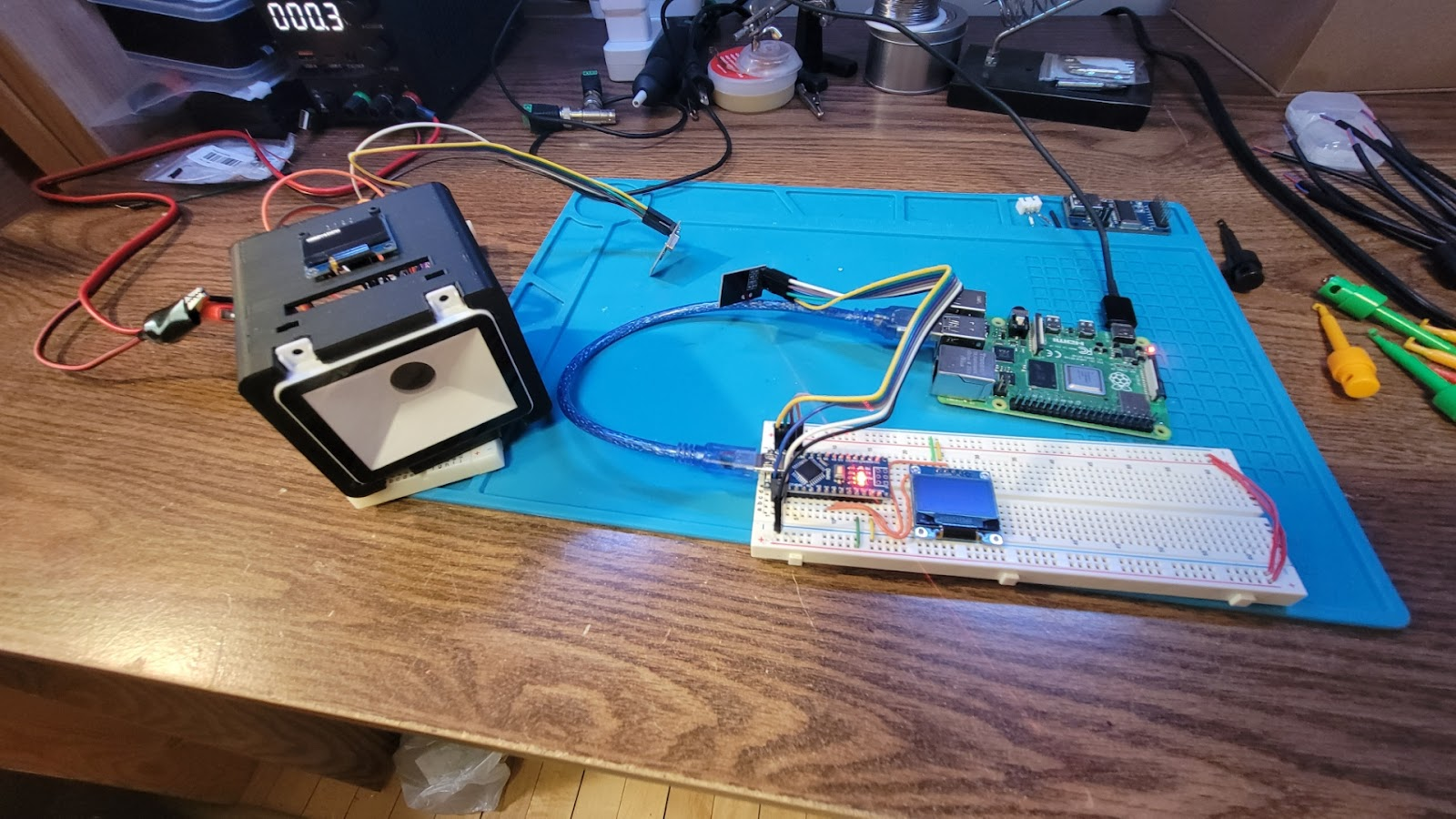
This week I added the screen the scanner. I tested the prototype code that displays the scanned input on the screen. The code needs improvement for ensuring all the characters are printed on the screen. This next week I will continue working on the code and work on the handheld scanner.
3/18/24 – 3/22/24
This week I made a prototype code that utilizes a 1in screen for the mountable scanner. I will be assembling and testing the scanner with a screen this next week. I will also start writing code for the handheld usb scanner. I will also be helping with the prototype mounts/ frames for the scanner. The 3d models will be printed, tested and revised this week.
3/11/24 – 3/15/24
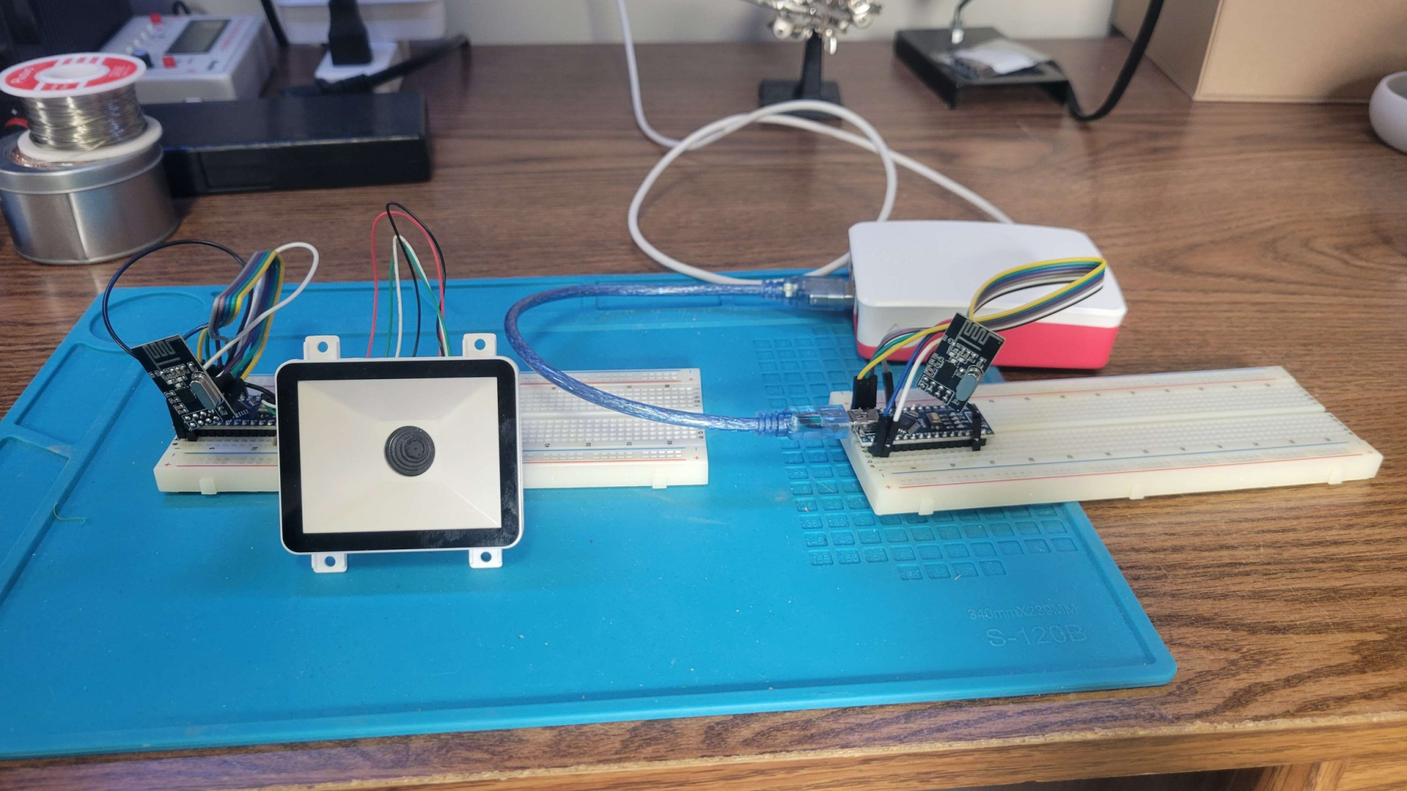
This week I worked more on the wireless communication code. The wireless modules are able to send the read strings consistently and can also have secondary information sent with it. The usb scanner, usb module, and oled screen has been ordered for the next step with the scanners. This next week I’ll setup code for adding the new screen to the existing scanner.
3/4/24 – 3/8/24
This week my team tested the wireless communication with the UART radio modules. These modules provided an easy way to send barcode data and many other forms of data with ease. The first prototype of the dataset server was also tested. My next task is to create cad for mounts for the scanner and add a screen.
2/19/24 – 2/23/24
This week my team worked on our CDR presentation. The presentation was given feedback on ways we could improve our project. One suggestion was that scanners that communicate with UART could be directly connected to the radio modules. Because of both communicating with UART the radio module could be programed to transmit directly what is received from the scanner. Other suggestions were made on simple improvements to our current plans.
2/12/24 – 2/16/24
This week we worked on the radio communication, scanner case modeling, and handheld options. Currently, we got some transmitters to “send” a packet of data but the receiver has not been able to receive them. A hand held option we are considering is using a USB scanner that connects to and Arduino that transmits the data to the loaf.
2/5/24 – 2/9/24
This week we assembled the scanner and uploaded code to scan bar and qr codes. We are able to read in the codes and print them to the serial. The next steps are developing the inventory system, design a housing for the scanner, setup the scanner’s screen, and research ways to increase the range of the scanner.
1/29/24 – 2/2/24
This week my team’s parts arrived. We started designing software to run the modules on an Arduino. This next week the new parts will be tested with a first version of the code.
1/22/24 – 1/26/24
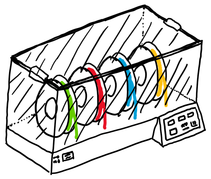
My team and I put together a general plan and list of parts for what we expect to work on over the next few weeks. We drew simple sketches of what we understand our project will be to ensure we all understood each other. Here is my sketch.
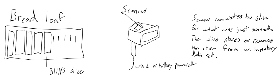
We ordered parts this week to get a jump on building a prototype. This next week I will read more of how the BREAD system is setup. I will also be researching existing open source barcode scanners and inventory management systems.
Coco Fabrication:

10/30/23 – 11/3/23
Electrical drawing created for heating control
Heater prototype parts received. Currently creating mounts for assembling prototype. The plan is to avoid irreversible changes to parts until the prototype proves the concept.
10/16/23 – 10/27/23
Worked with Growbot to fix small code error, and tested ideas to solve what happens when controller disconnects. This found a hardware limitation of RC receiver.
Chocolate Fab- Created BOM for prototype. Ordered initial parts. Created post of initial design.
10/2/23 – 10/6/23
Created safety manual for for angle grinder and drill press. Updated sketch to available components.
9/25/23 – 9/29/23
I created sketches of coco fab initial designs. Researched posable parts for melting control.
Growbot:
Spring 2023
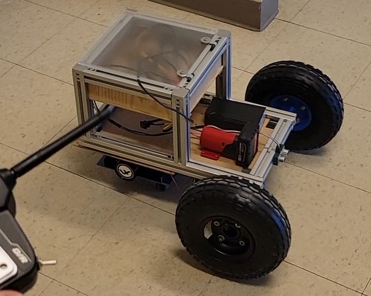
This past week I worked with the new Growbot team. The bot was disassembled during prototyping at the end of last semester. We reassembled the bot and flashed new code onto it. It now has limited movement.
Later in the week I reorganized and reworked the new code so that the new team can understand how it works and can easily make changes.
I made a basic program for manually driving Growbot and setting it into autonomous mode. This was done with a Flysky RC controller that an Arduino received the inputs to determine the mode and manual response. The old battery has been replaced with a Milwaukee M12 battery and the electronics are now in an enclosure.