
4/20/2025 – Open Source Thunniform Robot | Documentation and Design Expo
This week we spent more time working on documentation, and we presented our project at the OSHE design expo table. We were also able to successfully demonstrate the buoyancy system working!
4/13/2025 – Open Source Thunniform Robot | Starting Documentation
We started working on our final report and steps to replicate our project. We were able to fix the buoyancy control system to get it ready for demonstrating that we got it working. We ran into more issues with waterproofing and the tail motion system, and it doesn’t look like we’ll be able to demonstrate them.
4/6/2055 – Open Source Thunniform Robot | Crunchtime to Finish the Project
This week we were focused on assembling the mechanical portions of the project and integrating them with the electrical portions. Others on the team were working on writing ROS 2 nodes to control all of the mechanical systems from Raspberry Pi through the Raspberry Pi HAT. I helped with electronics-related issues that they ran into, and I helped with mechanical assembly where I could. We barely managed to put everything together before our project checkoff to discover that the tail mechanism broke and the body wasn’t waterproof. When we went to test the buoyancy control system a bug in the code drove the motor to its limit and kept going, burning out the motor. I’ve since set current limits on the motor drivers to hopefully avoid this in the future.
3/30/2025 – Open Source Thunniform Robot | Fish Assembly, Programming, and Piezo Disk Testing
Last week was dedicated to starting to begin fish assembly and also to putting together ROS2 nodes to manage all of the robot’s subsystems. I spent some time putting together a few new piezo disks and gluing them into the front half of the fish body. I also tried to do some frequency response testing for the piezo disks in water, but I was getting very confusing results. All of the disks had the same frequency response when doing a frequency sweep with the software I was using and with the disks separated by about three feet of water. In addition, as I was doing testing some of the piezo disks some began to stop working. I’m still not sure exactly what was going on with the frequency, but for the disks that stopped working it turns out there was water ingress through the PLA of the chambers that was shorting out the piezo disks.
3/23/2025 – Open Source Thunniform Robot | Hat Programming and Piezo Disk Testing
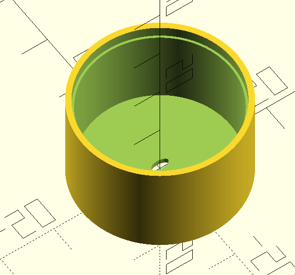
I tested libraries for servos, the IMU, and the temperature sensor. They’re all working. I also put some time into cleaning up the code I wrote and making it easier to work. I put some time into testing the audio amplification/piezo driver section of the board. both transmit and receive sides worked and had the expected gain. I also made a quick cad model for a cavity that will hold the piezo disk and let us put some type of potting compound over the piezo disk to waterproof it. We tried potting a piezo disk using one of these holders and they seem to work fairly well.
3/16/2025 – Open Source Thunniform Robot | Pi Hat Programming
Last week I worked on writing python code to interface with the PWM generator, ADC, and motor drivers on the Raspberry Pi Hat. I ran into some issues with the motor drivers, but I was able to solve them eventually.
The first issue I had was it seems the motor controllers need to alternate between driving and breaking to move motors. Alternating between driving and coasting doesn’t move the motor I was testing with. One of the motor drivers also had a soldering issue where there was slightly too much solder on the thermal pad underneath the chip which prevented the leads on one side of the chip from making contact with the PCB as shown in the diagram below.

I also have been getting unexpected behavior from the ADC where it doesn’t read voltages accurately and the voltage it reads increases over the span of a few seconds as multiple readings are taken, even if the voltage being measured is constant. Right now I think this is from not having enough decoupling capacitance, but it will take more troubleshooting to fully resolve.
In addition, last week I found a library for interfacing with the IMU we selected along with a library for controlling stepper motors from a raspberry pi.
- The IMU library I found handles reading from the IMU and it also handles converting raw IMU data to more useful data: https://github.com/OmidAlekasir/mpu6050?tab=readme-ov-file
- I found the servo library from a DigiKey tutorial that I plan to follow somewhat closely: https://www.digikey.com/en/maker/tutorials/2021/how-to-control-servo-motors-with-a-raspberry-pi
This week I plan to test both libraries I found last week. I also plan to troubleshoot the ADC, work on reading the temperature sensor, and test the audio amplifier for the acoustic communication system.
3/10/2025 – Open Source Thunniform Robot | Assembly and Testing
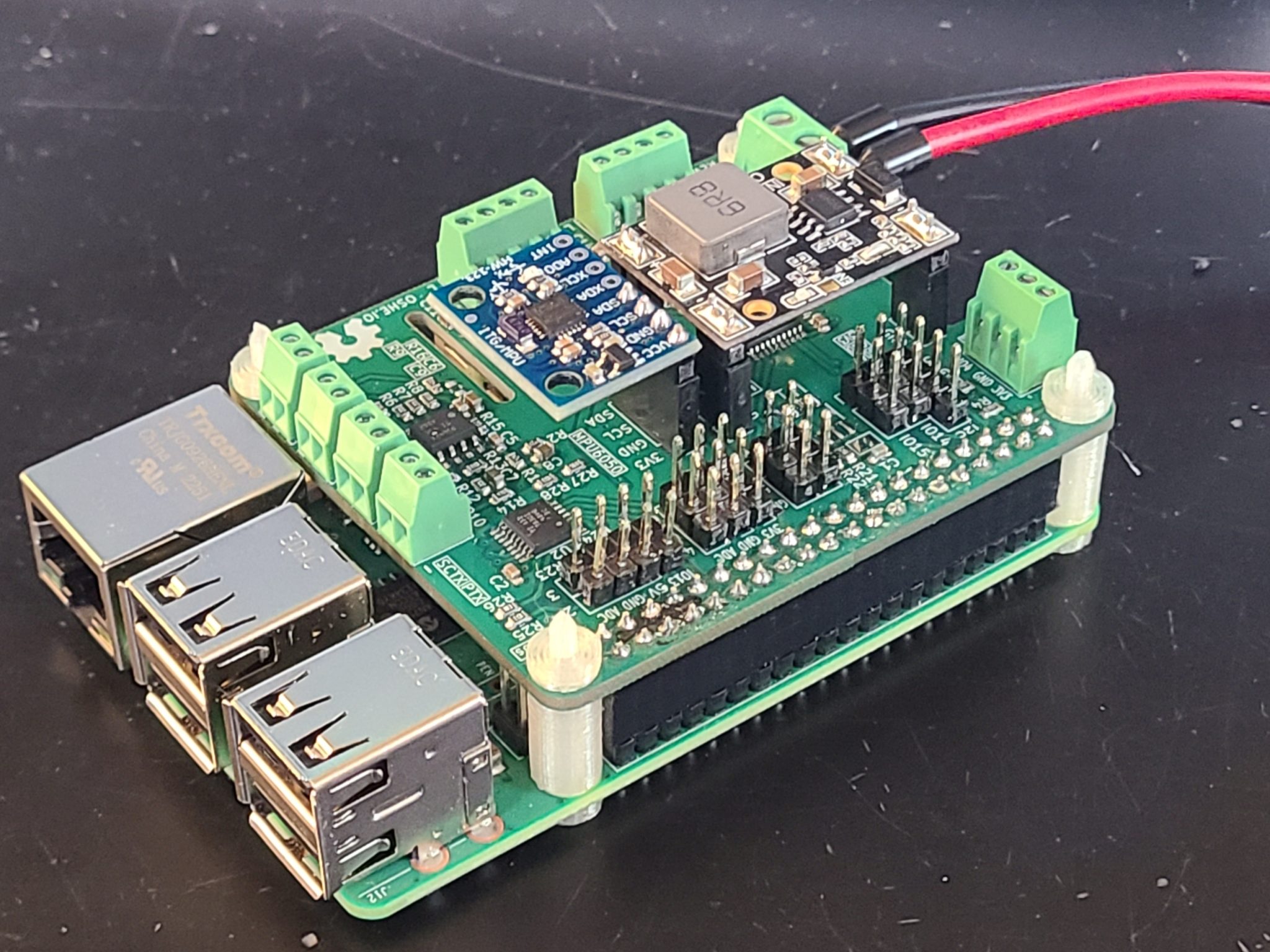
This week was much more productive than the last couple of weeks. I wound up assembling the whole HAT board in one go, but for testing I tested the Vbatt to 5 V conversion without the Pi connected. Then I applied power to the 3.3 V pins with a current limited power supply and I measured the current to get an idea of if there were any issues. I measured about 100 uA of current draw which is reasonable for standby. Finally, I put the HAT on our Raspberry Pi and ran a scan of I2C addresses to make sure all the chips on I2C showed up. They all did, indicating that the board works.
After confirming that the board appears to work I moved on to writing Python code to control the motor drivers and read from the ADC. I got the ADC working without any trouble, but I’ve been having a hard time getting the PWM chip/LED driver to output PWM. My main task for this week will be to find the issue here and fix this issue to get the motor drivers working.
3/3/2025 – Open Source Thunniform Robot | Assembly Preparation
To be honest I didn’t get much done this week. I put some time into thinking about the best way to assemble and test the Pi HAT. I’m not sure whether it would be best to assemble it all at once or to assemble it and test it in parts. I’m leaning towards the second. At the very least I will assemble and test the ADC and PWM chips before adding the motor driver, and I will assemble and test the power conversion before I plug the hat into the Pi. The boards came in over spring break last week, so I plan to get them assembled this week.
2/20/2025 – Open Source Thunniform Robot | Critical Design Review
This is a very delayed update for last week. Last week I didn’t make all that much progress on enterprise related work. I finalized the PCB and we ordered it from JLCPCB. I also spent some time preparing slides for critical design review which is our mid-semester progress update.
2/4/2025 – Open Source Thunniform Robot | PCB Design
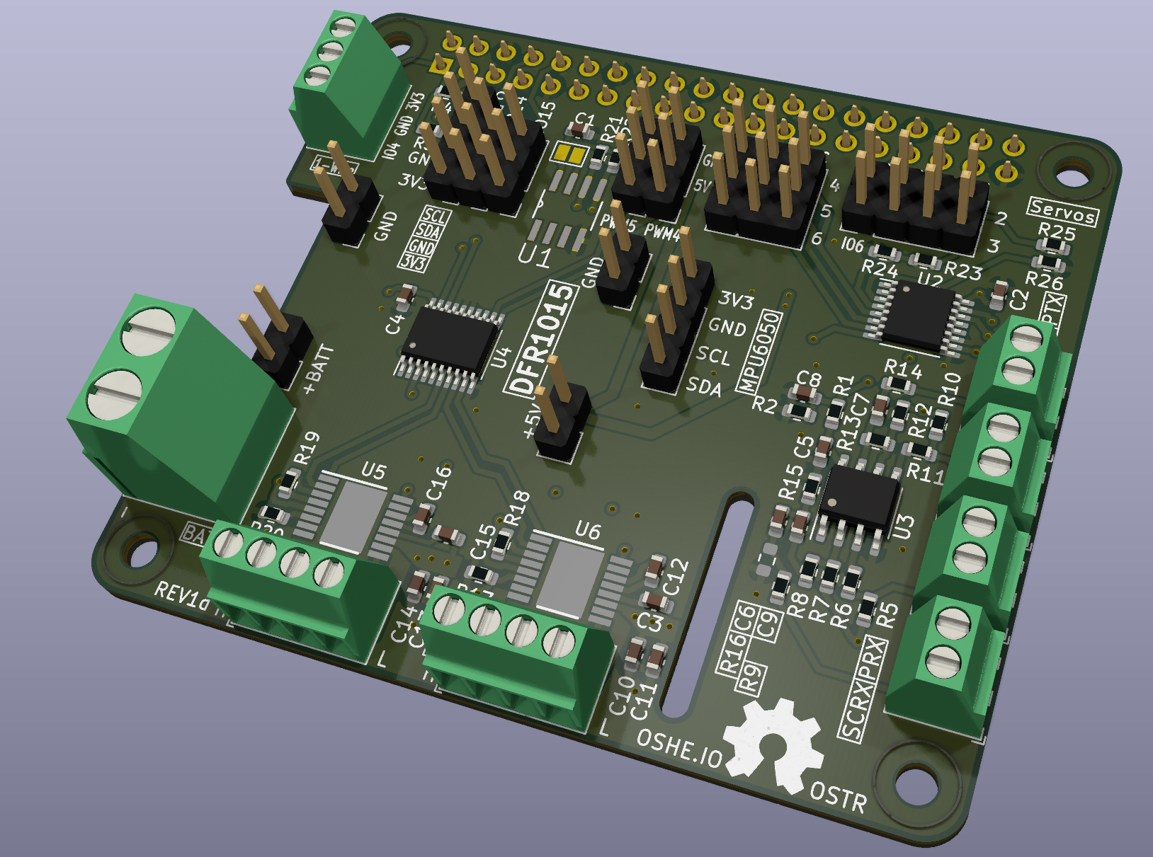
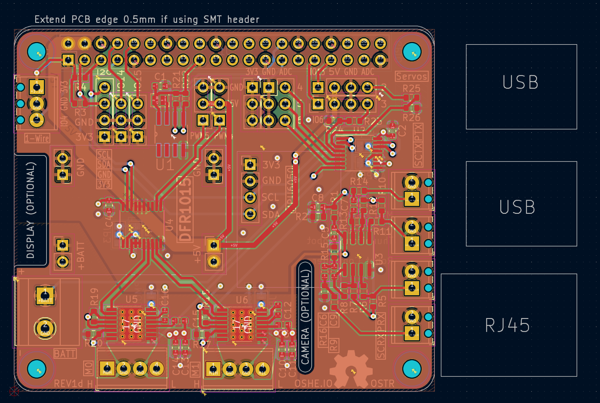
Today I’ve been finishing up my work on designing a PCB for the Raspberry Pi HAT. I decided to plan on a 4-layer board with the stackup shown in the table below. I used KiCad’s HAT template as a starting point that provides the border, mounting holes, and connector. A few pieces of note are that three sides of the HAT will need to be exposed, plus most of the top side, so that the connectors can be accessed. In addition, header pins were included so a DFR1015 buck converter could be included to step down the battery voltage along with a MPU6050 IMU breakout board can be mounted to the HAT. I did my best to label all of the connectors for ease of use. The layout is a little bit messy, but overall I’m happy with it. Hopefully it works 🙂
| Top | Routing/GND |
| Inner 1 | GND |
| Inner 2 | Power (14.8V & 3.3V planes) |
| Bottom | Routing |
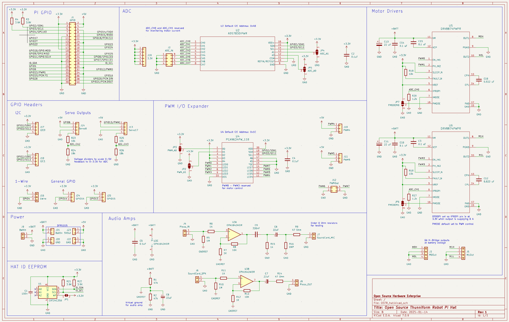
1/26/2025 – Open Source Thunniform Robot | HAT Schematic Capture
This week my focus was finalizing the schematic for the Pi HAT. Last week I got through selecting a PWM chip, an ADC, and motor drivers. With that, I got through designing the external circuitry for the motor drivers and capturing everything else required to interface with sensors, motors, and the piezo disks. Right now I have a couple of extra connectors in case plans change at some point after we order the board and we wind up needing them. Next week I plan to finish the PCB layout so we can put in an order the week after.
Spring 2025 Update 1 – Open Source Thunniform Robot | Semester Plans
Last semester I was able to get functioning hardware together for the transducer, and other members of the team wrote code to send data acoustically using the transducers. Other members of the team also put together a prototype buoyancy control system and modified the OpenFish design to support steering.
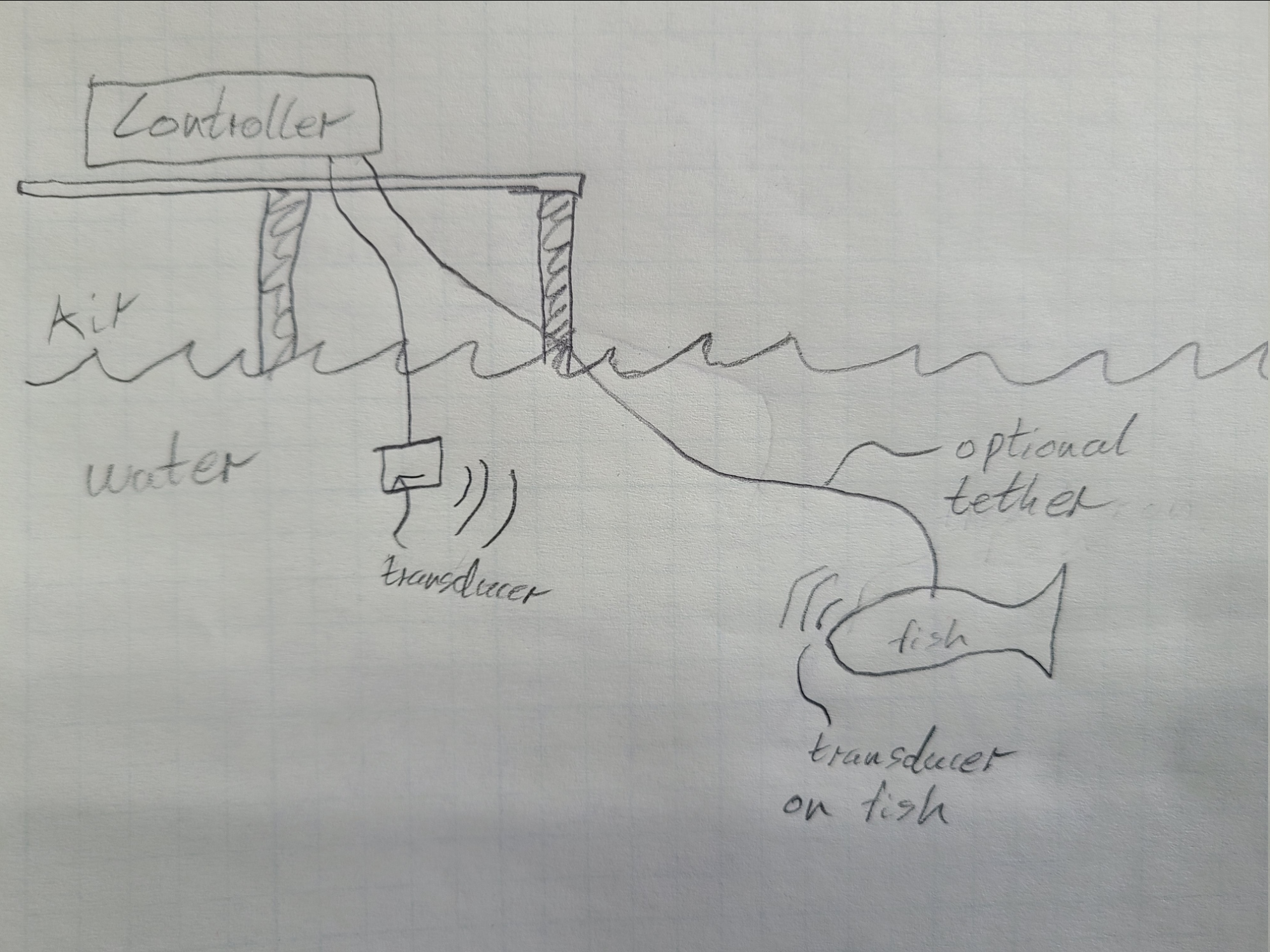
This semester we plan to integrate all of the separate systems we’ve developed into a new fish body. To support this my first goal for this semester is to design a HAT for a Raspberry Pi 3B+ that will facilitate connecting the transducer, motors, and sensors to the Pi. Below are two diagrams, one depicting the two communication methods we will use to control the fish robot, the other a sketch of what systems need a connection to the Raspberry Pi.
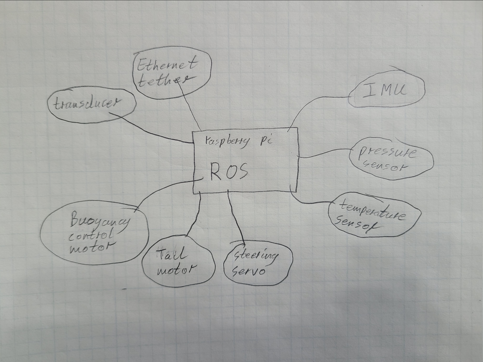
Below is a list of all of the systems and components that will need to interface with the Raspberry Pi along with a brief description of how they need to interface with the Pi and how it will be implemented on the HAT.
| External Device | Interface | Notes |
|---|---|---|
| Transducer | Audio Amps & USB Soundcard | Piezo disks will connect to the HAT, signal will be amplified, and another connector will provide a connection to the USB soundcard |
| Tether | Ethernet | Ethernet port on Pi |
| IMU | I2C | HAT will have I2C connector |
| Pressure Sensor | Undetermined | Undetermined |
| Temperature Sensor | One-wire | HAT will have a connector with 3.3V, GND and a GPIO pin |
| Steering Servo | Standard RC servo pulses, Analog potentiometer feedback | HAT will have a servo connector that exposes a GPIO pin to control steering. Another pin will be made available that steps down the 5V feedback signal to 3.3V before sending it to the ADC |
| Tail Motor | PWM | The HAT will have a PWM motor driver capable of providing enough current to drive the tail motor |
| Buoyancy Control Motor | PWM | The HAT will have a PWM motor driver capable of providing enough current to drive the tail motor |
9/29/2024 – Open Source Thunniform Robot | Hydrophone Prototype
My main goal for this week was to build a prototype of a hydrophone. Originally my plan was to come up with a list of parts to order for the Gladys hydrophone, but the parts list came out to be over $100. The two biggest expenses were the special resin that DJJules used and piezo cylinders. To save some money I switched to working on a prototype with parts that we already had on hand, namely piezo electric disks, an LM358 op-amp, and Shore A 15 Hardness silicone resin. I was able to record audio with a piezo disk, and after potting a second disk in silicone I was able to send data through about 12 in. of water using fldigi.
Sam volunteered start working on the BMS, so I haven’t spent any time on that this week.
To do list for next week:
- Figure out how we should connect the hydrophone to our raspberry pi. A sound card would work, but I want to figure out what we can use that would allow us to use ultrasonic frequencies.
- Set up our raspberry pi. Install an OS and ROS.
- Determine internet requirements to link ROS nodes.
9/22/2024 – Open Source Thunniform Robot | Control & Hydrophone
This week we decided that radio-based communication will have too short of a range for us to continue pursuing it as an option for this project. Because of that I haven’t spent any time working on my radio-related goals for last week. Instead I’ve been doing research on hydrophones and drive circuits for piezoelectric elements.
I found this project: https://www.instructables.com/The-Gladys-Hydrophone/, by DJJules, which I think will work well as a base for us to build off of for our project. His circuit is pretty much just a non-inverting op-amp amplifier with some extra protection circuitry. My plan is to design a PCB with a single one of his 9V circuits. I think I’ll be able to use a dual OPA1642 and use the other op-amp in reverse to drive a piezo element. I’m not sure how to switch between TX and RX. Maybe I can just couple both the input to one amp and the output of the other amp to the piezo cylinder. That would only be half duplex unless I did some careful filtering and put RX and TX on different frequencies, but it would be quite simple. I guess to do full duplex I would have to do some filtering anyways. I’ll keep working on this tomorrow.
We also decided to go with a raspberry pi for controlling everything so that we can possibly do some light computer vision stuff. It will also allow us to use ROS and GNU radio.
To do list for next week:
- Test piezo receive/drive circuit with generic op-amp and piezo discs that I have on hand.
- Design PCB for custom hydrophone based on the Gladys Hydrophone: https://www.instructables.com/The-Gladys-Hydrophone/
- Draw a rough diagram of the electrical side of the robot to roughly determine power requirements.
- Start work on battery management system.
- Look for existing systems that we could use while only doing minimal design work.
9/13/2024 – Open Source Thunniform Robot | Project Diagram
To do list for next week:
- Find easy to use radio dev board similar to the nRF24L01 that operates at less than 2.4 GHz for underwater testing. Probably 915 MHz.
- Develop op-amp drive circuit for a piezo bender that can be driven by a pi pico, or select a commercial piezo driver.
- Search Digikey for piezo drivers
- If none found do some research breadboard an op-amp amplifier that can take a 3.3 V peak square wave as an input.
- Find formula for RF attenuation underwater.
- Test WiFi range underwater with a pi pico configured as a WiFi access point.
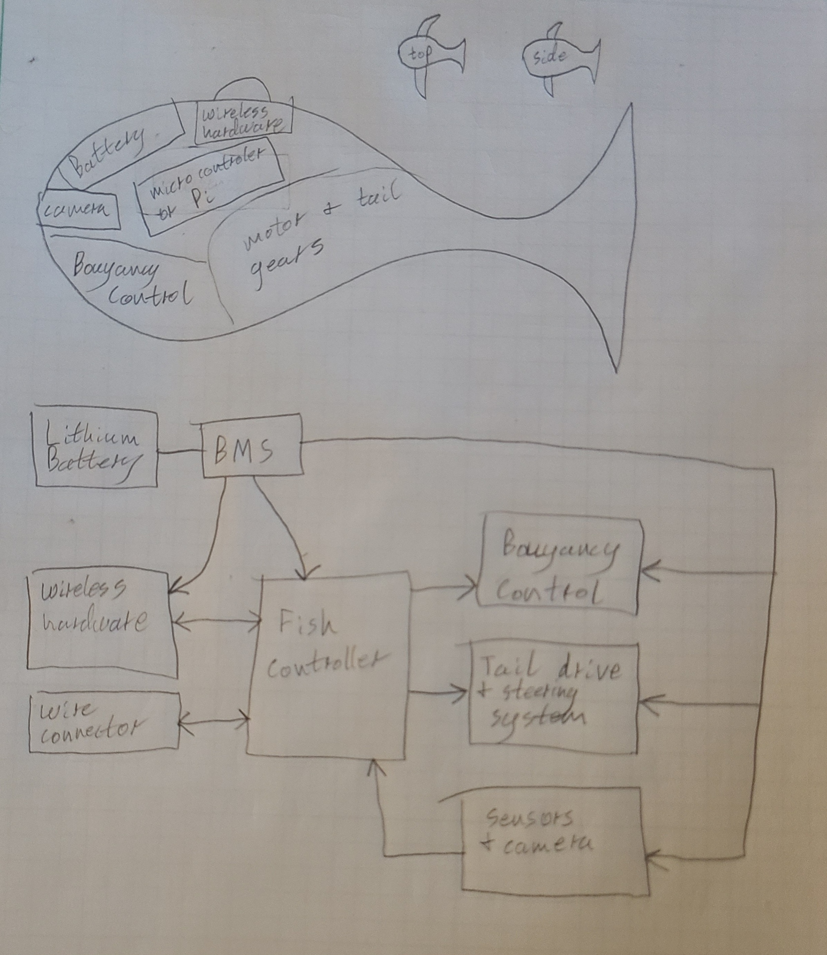
Sketch of expected robot design
4/13/2024 – ATX Power Supply | Documentation
This week, as we’re waiting for our boards to come in, we’ve begun to work on documentation for the ATX power supply project. Not too much to talk about here.
4/6/2024 – ATX Power Supply | Finishing Layout
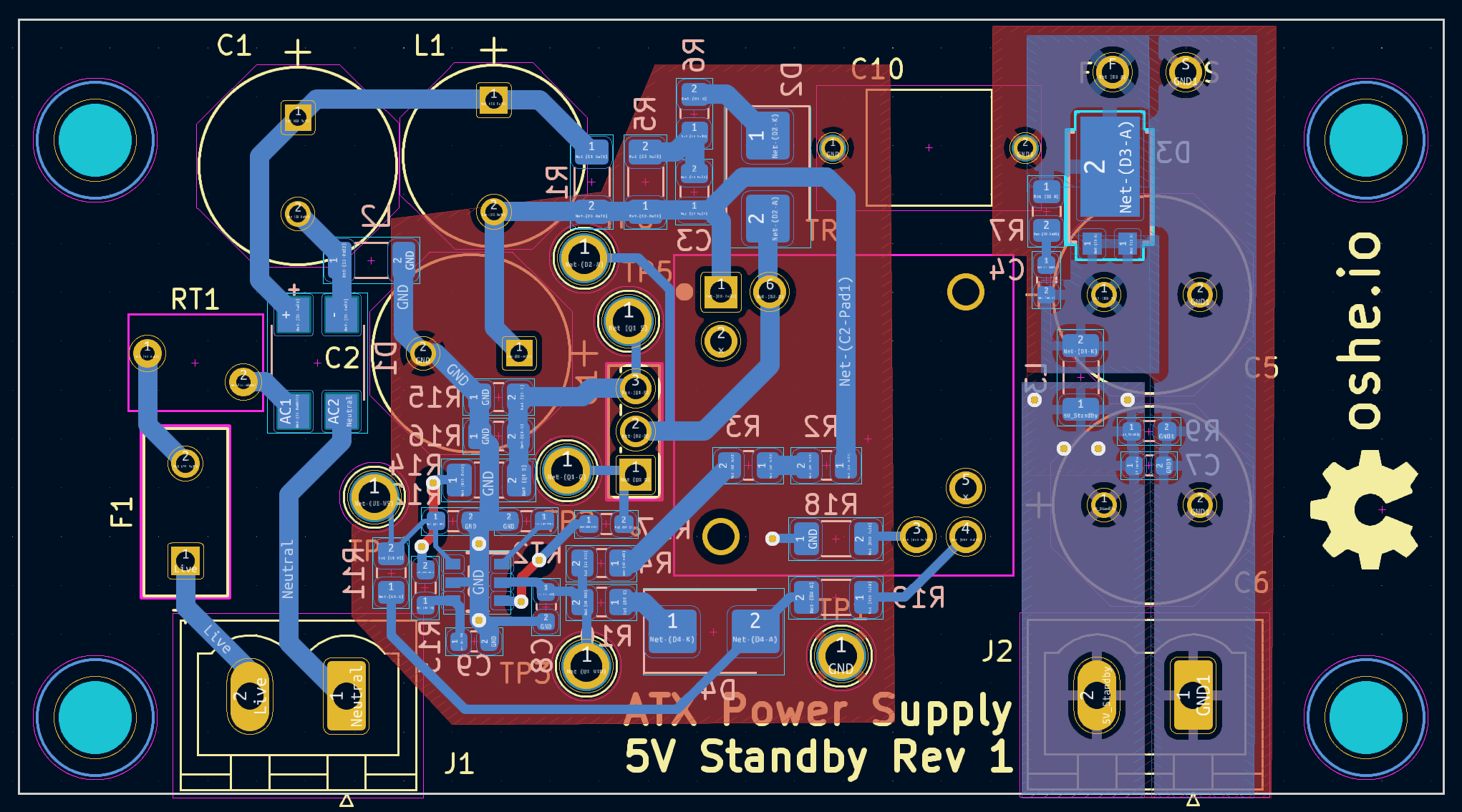
This week I finally got around to finishing my layout. Because I’m mostly copying the evaluation board for the initial revision of the 5V standby flyback I followed the layout of the evaluation board closely. I did wind up making a few tweaks to accommodate some different sized components that I have. My final layout is below.
Going into next week we’ll order boards and components. Once they come in it’ll be crunch time to try to get them assembled and working before design expo.
3/30/2024 – ATX Power Supply | Still Layout
I didn’t put as much time into layout this week as I should have, so I don’t have my portion done yet. unfortunately this means next week will also be layout and there will be very little time for troubleshooting between when the boards come in and the end of the semester.
3/23/2024 – ATX Power Supply | Layout
This week I got started with layout for the 5V standby section. I hope to be finished sometime next week.
3/16/2024 – ATX Power Supply | Design Review Preparation
This week was mostly dedicated to cleaning up schematics and making a document with all of our design decisions to send to our sponsor for review.
3/9/2024 – ATX Power Supply | Component Selection
This week I got through compiling a BOM and assigning footprints for the 5V standby section. This has mostly been a matter of going through the BOM for the evaluation board I’m basing my design on, searching the components on Digikey, and putting them into my own BOM. Next week my team will be doing a schematic review with Plexus, who’s sponsoring this project, and I’ll get started on layout for the 5V Standby section.
2/24/2024 – ATX Power Supply | Transformers and EMC
This week I got word from Wurth Elektronik that they shipped samples of the transformers for the 5V standby flyback. I’ve also spent some time on the input EMI filter design based on a YouTube video I found. I’ve chosen initial values for X and Y capacitors based on the video’s recommendations. This week if I get some time I’ll spend some time on Digikey looking for a common mode choke. From the research I’ve done, I need to find one that has a decent amount of attenuation at our switching frequencies (60 kHz and 100 kHz) and their first few harmonics.
2/18/2024 – ATX Power Supply | Finishing 5V Standby Design
When I was doing my portion of project planning I said that by the end of this week I’d be done with the 5V standby design and have everything put into KiCad. I’ve tried to work through the design guide in the UCC38C42 datasheet for a while, but I’ve never been able to figure out a way to make sure my design will actually work when I get done with it. I did some more searching, and I stumbled across the UCC28704 and its evaluation board. It happens to take line voltage and step it down to 5V at 2A . . . exactly what I need. The one issue with it is the transformer it uses is only available directly from Würth Elektronik. The core appears to be available on DigiKey though, so I can always wind my own. Long story short, I migrated the evaluation board schematic into KiCad, and it will be the first iteration of our 5V standby supply.
2/10/2024 – ATX Power Supply | Transformer Selection
This week I found a transformer that should work with the controller IC I selected. This turned out to be a bit of a process, and the transformer I found appears to be the only transformer on DigiKey or Mouser that meets the specs I need. I hoped to run through some calculations and select a mosfet to use, but I ran out of time in the week. Hopefully I’ll get a chance to get some more work done tomorrow.
2/3/2024 – ATX Power Supply | 5V Standby Stuff
This week I read through the datasheet for the UCC38C42 PWM controller that I’m planning to use for the 5V standby. I have a better understanding of how it works, and I found design equations from the datasheet that I can use. Next week my goal will be to find a transformer and to select a MOSFET.
1/27/2024 – ATX Power Supply | The plan and my plan
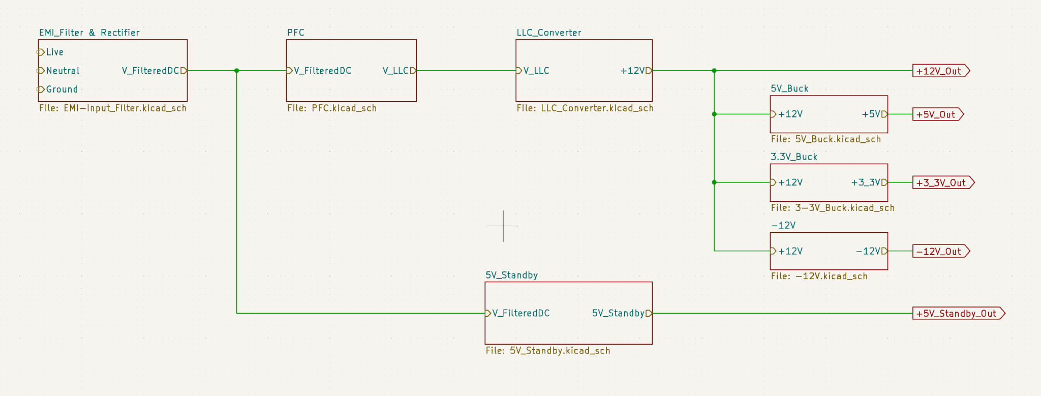
To start off the semester we’re doing a thing where we each come up with a drawing of what our project is. Then we’ll compare them to make sure we’re all on the same page. I came up with a block diagram of our project in KiCad of how our project’s circuitry will be laid out. Going from the mains input to the main outputs, we have some EMI filtering going into an active power factor correction circuit, followed by an LLC converter that will produce a 12 V output. This 12 V output is then converted to 5 V, 3.3 V, and -12 V. Finally, a 5 V standby output is also required, so we’ll have a second converter coming out of the EMI filtering to produce the 5 V standby rail. This is a slightly atypical organization, but we think it will be simpler to design and get working. Typically there’s one main converter that produces all four main rails with a smaller 5 V standby converter.
My goal for this week is to finalize the 5 V standby circuit. Right now I have a circuit from TI’s webench power circuit generator, but I’m hesitant to blindly trust it. Throughout this week I’ll go through the datasheet for the flyback chip I’m using and verify that the circuit I have looks like it should work.
11/12/2023 – ATX Power Supply | 5V Standby
We’ve began selecting transformers and MOSFETs for the PFC and converter. This week I worked on finding a controller for the 5V standby rail. The target for this rail is 2 or 3 A at 5V, and it needs to be isolated. Searching TI’s WEBENCH design tool led me to the UCC28742. This chip looks promising. It requires relatively few external components, it’s one of the cheaper options, and it’s in stock on DigiKey. Next week my goal will be to come up with a rough design for this chip that will work well next to our main power conversion stages.
11/4/2023 – ATX Power Supply | Development Boards
In order to do some amount of testing of our design before we order parts we ordered a couple evaluation boards this week. For our LLC chip we had two options. The first has a single 120Vac input and included PFC correction and everything else that’s necessary. The second requires a ~400Vdc input and a 120Vac input, and it doesn’t have PFC. We chose to go with this board along with an evaluation board for the PFC chip Ben Abel has been working on a design for. Hopefully some hands on experience with these evaluation boards will give us a better understanding of how the chips we’re using work, and they’ll help us improve our design.
10/28/2023 – ATX Power Supply | Switching to an LLC for Main Power Conversion
This week and last week we made the decision to use an LLC converter for our initial conversion rather than a flyback. In our research it seemed like flybacks are typically only used for lower power applications. We plan to use the UCC256404 controller from TI. I found a Simplis simulation model and a spreadsheet to assist with calculating component values for the LLC circuit. We also found a series of SMPS transformers on DigiKey that we plan to use.
10/6/2023 – ATX Power Supply | Finding a Flyback Controller
My goal for this week and last week was to find a potential flyback controller IC and develop a spice simulation for it. From what my team has found so far a flyback controller may not be able to produce enough current, but the relative simplicity of a flyback makes it a very appealing option. After some searching I found the UCC28C52 from TI. This chip looks somewhat promising. Section 9.2 of its datasheet gives a schematic for a isolated 12V power supply rated for 4A. That’s a lot less than what we need, but hopefully with a different mosfet we can get closer to out 50A target.
There’s a PSpice model available for the UCC28C52, and I’ve been working on converting it to a QSpice model so we can use it with the rest of our simulations. I haven’t gotten it working yet, but I think I’ve gotten it down to one major error. After I work through this error it will hopefully work. Otherwise we may need to look at simulating the flyback in PSpice.
9/23/2023 – ATX Power Supply | Getting Started with EMI Filtering
This week’s goal was to learn what conducted EMC requirements we need to meet and how to design an EMI input filter to meet them. Ideally I’d be able to choose components for the input filter as well, but I thought we may need to know more about our switching architecture first. To begin, I looked for the conducted emissions limits we’ll need to meet. According to the Intel ATX Version 3.0 Design Guide we must meet Class B for both conducted and radiated emissions for FCC Part 15, EN55023, and CISPR 22. Being in the U.S. I decided FCC Part 15 would be a good starting point, and luckily these limits are readily available through the National Archives eCFR system. Conducted emissions are in a table under §15.107.
| Frequency of Emission (MHz) | Conducted Limit (dBμV) | |
|---|---|---|
| Quasi-Peak | Average | |
| 0.15 – 0.5 | 66 to 55* | 56 to 46* |
| 0.5 – 5 | 56 | 46 |
| 5 – 30 | 60 | 50 |
It’s nice to know what the limits are, but the limits themselves don’t say much about how to meet them. Fortunately the internet exists, and I was able to find this YouTube video that discusses choosing initial values for EMI input filter components. With this video and the above limits, I believe I’ve reached my goal this week, and in the future it should be relatively simple to choose components. Next week we’ll need to put a lot of work into ironing out our DC-DC conversion and case design.