
Current Engineers: Lily Hubbard and Sierra Derusha
Previous Engineers: Ben Steinbach
Immersion Circulators (most commonly known as a “Sous Vide Cooker”) are specialized devices that are used to heat water to a specific temperature and maintain that temperature for extended periods of time.
Objective:
The primary goal of the Immersion Circulator Project is to provide a method for constructing a cheap and simple immersion circulator with the same functionality of other commercially available devices. This project also has the focus of creating a solution that is scalable for different applications; whether you are considering this project for at-home use or you want to use it in your restaurant, there are different options for the construction of the device that fit your use case. The final goal of this project is to create a fully functioning immersion circulator that can reach the temperature range of 100°F–200°F, whilst also providing additional features such as: a timer for cooking, a temperature gauge, and scalable modules so that the user can decide how many heating/circulating modules they want to use to heat their bath.
Functional Goals:
- Casing will be provided for the heating element of this project. Completed
- Housing will be created for the electrical components, separate from the heating element. Completed
- The water temperature will be able to reach both ends of the range 100℉-200℉. Completed
- The circulator should integrate with an application that allows for remote control over Bluetooth. Incomplete
- The circulator will heat baths of varying sizes, up to at least 10 gallons. Completed
- The circulator will heat water for a 24-hour period. Completed
- A screen is provided and integrated in the electrical casing. Completed
- Submerged components will be waterproof (when applicable). Completed
- There will be accessible buttons that change the time and temperature, as well as flipping through multiple screens. Completed
- The temperature throughout the bath will be consistent. Completed
Value-Added Goals:
- The device will display wattage.
- The app will be able to take a volume measurement.
- The app will be capable of calculating efficiency by using wattage and volume.
Heating Element:
Initially we decided to create a heating element using nichrome wire and a power supply. This heating element was constructed from brass tubing and lengths of nichrome wire wrapped with varying numbers of windings and was tested at different voltages and currents, but the results were all the same: there wasn’t enough power to heat the desired amount of water in a reasonable amount of time. It was almost certain that the system would reach equilibrium between heat added and lost before the target temperature could be reached. This design also suffered from another issue: the kapton tape that was being used to insulate the nichrome wire wasn’t as heat resistant as we originally thought. Kapton Tape is rated as being safe for use up to 500°F, with some types being able to withstand up to 725°F. Our tape was rated under 725°F. During one of the tests, the nichrome wire glowed and the kapton tape began burning immediately when power was applied. From that point on, we decided that the safest option would be to go with an off-the-shelf heating element instead. Most heating elements today (like the ones on your common electric stove) are an alloy of high resistance contained inside a sheath of Magnesium Oxide powder, which is a good thermal conductor but a poor electrical conductor.
The next considered design for the submerged heater/circulator device was a waterproof box containing the electrical connections and housing for the water pump to sit inside. However, after discussing this idea with other members of the enterprise and our advisor, we decided on a simpler approach, as we were unsure if a 3D printed waterproof box would be a smart move. Instead of trying to create an entire waterproof housing, we decided it would be more time efficient to cover the connections themselves via some waterproof material like epoxy, silicone paste, or an adhesive shrink tube.
Our final design has three components: a washing machine heater, a water pump, and a thermocouple attached together with wire mesh, hose clamps, and a strong adhesive. This design has been the easiest and cheapest to assemble, making this one of the more beneficial methods. Additionally, it meets all heat and water requirements that we foresee needing.
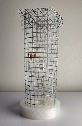
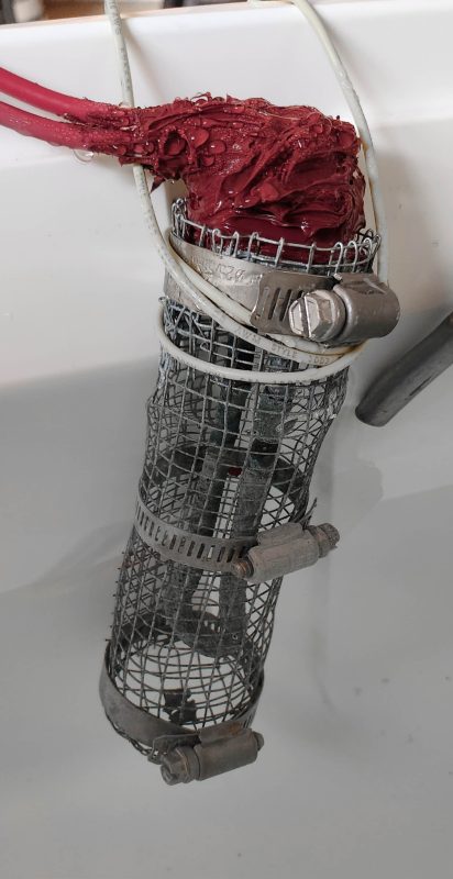
Figure 1: Original Design for Waterproof Housing Figure 2: Final Design for Heating Element
Power System and Safety:
This project requires a large amount of power due to the large volume of water and its high specific heat capacity. Most of the power drawn goes to the heating element as a result. However some of the power is drawn in parallel to drive a 12V DC circuit via a wall plug 12V power supply which is connected to 120V supplied from a provided outlet. To protect the circuit, we integrated a light switch into the housing for electrical components. Additionally, there is a 15A breaker installed into the circuit to prevent run-away current in the event of an emergency.
ESP32 Coding:
The program is written entirely in Arduino C. The “brain” of this project is an ESP32 Metro, which we selected because of its ability to drive the OLED screen at a higher refresh rate than an Arduino Uno. This is because the ESP32 metro has a higher memory capacity than an Arduino Uno despite these two options being financially equivalent at the time of writing.
The display is an OLED screen communicated with over SPI and is powered by 12V DC. Currently, the ESP32 allows for the measurement and reading of our times and temperatures; it allows you to set and observe a timer, while also setting and observing temperatures from 0℉-200℉. We chose to use an OLED screen due to its high contrast and reconfigurability. The OLED screen allows the user to show any kind of symbol and fonts of their own design more easily when compared to an LCD.

Figure 3: OLED Screen with Temperature and Time Displays
One of the first issues we ran into while programming was the poor refresh rate of the OLED screen. It was fairly low, due to the fact that we implemented a polling loop to detect button presses to update the screen. To resolve this we switched to using hardware interrupts when buttons are pressed. The screen is printed whenever possible based on the values. This has resulted in a much more responsive screen and control setup.
We had two options to create the capability of switching between Fahrenheit and Celsius: have two different values and update both whenever one was pressed, or work from a single value that was just converted before it displays. The latter was chosen, because it meant less calculations to complete per button press. Additionally, this made it impossible for the two values to get out of sync.
Another issue we encountered was with the thermocouple. It would occasionally send back non-number values, which represented error codes. The function isnan() was used, which returns a non-zero value if the argument x is a Nan and returns a 0 if not. We checked to see if the values being recorded were in the possible range of values for a measurement (0-200°F). If it was not a number or if it was outside the possible range, we used the previously averaged value instead. It was crucial that these values were filtered from the input stream, as they weren’t displayable temperatures.
Furthermore, the thermocouple began outputting incorrect values that weren’t within a realistic range. These also had to be filtered out. This was resolved by averaging together a set of measurements and calculating the difference between the average and previous temperature readings. The difference between the current reading and the average of previous readings was taken and if that difference was larger than the set value (currently at 5), we threw out the current reading and used the most previous average instead. If the value is 5 degrees below or above, it’s thrown out.
To make sure the heating element doesn’t have to be consistently on (pulse), we implemented a hysteresis value. This creates a buffer zone in between the temperature at which the heating element turns on and off. The temperature must go above a specified value to turn off and below a separate specified temperature to turn on. This reduces the total amount of time that the heating element exists in a powered state due to small fluctuations in temperature and makes sure that the system is actually reading a dropping temperature before activating.
Electrical Wiring and Pump System:
The electrical system of the immersion circulator can be split into three different voltage levels. The first of these levels operates at 120 VAC and includes the heating element, the circuit breaker, light switch, relay and 12DC power supply transformer. The circuit breaker and light switch are in series to provide a means of cutting off power to the entire machine at once, either at the user’s discretion, or if current becomes too high. The connections from these are then routed to two circuits in parallel. One of these circuits includes a relay in series with the heating element to heat the water in the bath. The other is connections to the prongs of the 12V DC power supply. This power supply provides 12V DC power to a lower power system that drives the pump, a fan to cool the relay’s heat sink, and also the voltage regulator set to 5V to power the ESP32-metro. This final system is a primarily 3.3-3V system driven by the ESP32 Metro powered by the 5V regulator. This voltage regulator serves to further de-couple the ESP32 from the noisy 12V circuit which has two different motors on it that can interfere with the sensitive measurement from the thermocouple. This final low voltage system also contains all of the wiring for the SPI chips, button measurement pins and the output to the relay for controlling the heating element.
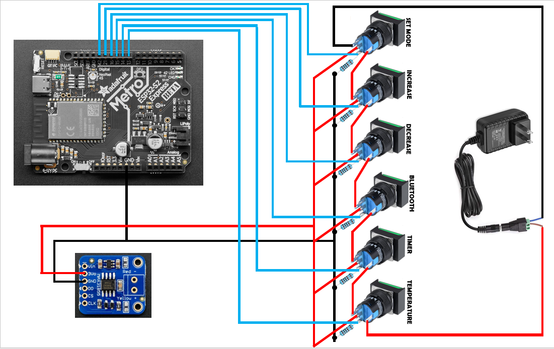
Figure 4: Wiring for Push Buttons

Figure 5: Wiring for Power System
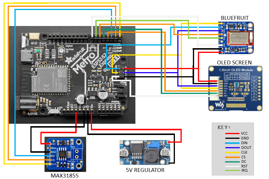
Figure 6: Wiring for ESP32
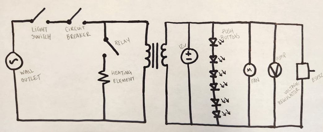
Figure 7: Circuit Design for Entire Project
Nearing the end of our project, we connected the ESP32 to our wall socket 12V power supply and found that our ESP32 was registering phantom button presses. This was observed through the rapid toggling and value displacement on the OLED display screen. We began by disconnecting the push buttons, but the issue remained. We questioned the validity of the power supply, but when tested with a multimeter, remained true to its 12V rating. The last thing to check was the pump.
Originally our team purchased pumps that were rated for 3-5V, with the intention of only using one of the pumps. Unfortunately, there was some miscommunication and team members believed that these were rated for 12V. To solve this issue, we replaced the pump with a new, 12VDC pump. An alternative solution to this could have been purchasing a 5V regulator with a 12V input. At 12V the pumps seemed to be working really well, whereas if we had opted to stay with the 5V pump the circulation in the water would have been greatly reduced.
Our new pump was only rated for 158°F submersion, which did not comply with our 200°F maximum temperature goal. We determined it would be best to keep the pump, but attach it above the water, that way we have an ideal pump that won’t melt. We secured the pump to the top of the tank with Velcro and placed metal tubes on each shaft, to reach below the water line.
App Development:
The purpose of the integration of an app in this project is purely for user ease. The device is fully capable of functioning without input from the android app. The app interacts with a Bluefruit SPI Friend via Bluetooth for temperature reading as well as timer readings and settings. Within the app, the user is able to do the following from the comfort of their couch: set a timer, see how much time is left for the cook, change the temperature of the immersion circulator, and see the current temperature reading.
The app was created using Android Studio and coded in Java. It consists of a home screen and three fragments: a temperature screen, a time screen, and a screen for settings. The app updates the box via “heartbeat” every half second. Additionally, it incorporates a color scheme similar to the box, but by changing values in the colors.xml this can be altered.
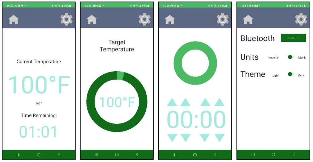
Figure 8: Screenshots of the App
Electrical Housing:
From the beginning of the project it was established that the electrical components would all be held in a box for the sake of appearance and safety measures. The design of this was debated back and forth, as we discussed what would be the best way to ensure the OLED screen is seen, the applicable cables can be accessed outside the box, the buttons can be pressed without disrupting the integrity of the box, and the power button (the wall switch) can be easily accessed but not in the way.
As you can see in Figure 9, the box isn’t a typical six-sided box. We added a seventh panel that’s tilted for ease of use and visibility. There are seven holes on the front panel: six for the buttons and one for the OLED screen. There are two cutouts on either side of the box for cables. The light switch was moved from the front to the back of the box to prevent clutter and provide a cleaner look.
The electrical housing was built using CAD software and created with a 3D printer. Each panel was created in a separate file, totaling up to seven files. The CAD software used in this project was Autodesk Fusion 360 (as displayed in Figure 10), but we believe the same steps can be taken with FreeCAD as the pieces are very simple. Additionally, the 3D printer we used was an Ender Pro 3, but the files can be used and printed through whichever the user chooses.
Initially we stumbled upon printing issues, as no one in the team had much experience using a 3D printer. The first few prints were warped and stringy, and we spent many days researching and re-printing. After adjusting the bed height and temperature, we finally started getting prints that we could use.
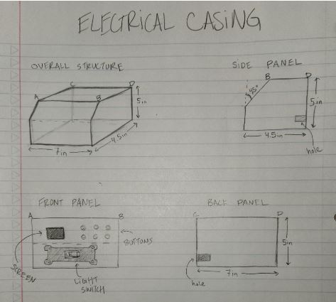
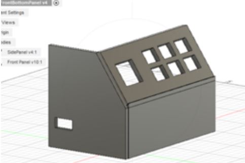
Figure 9: Electrical Housing Initial Design Figure 10: Electrical Housing CAD Design
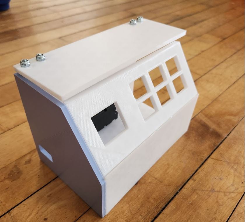
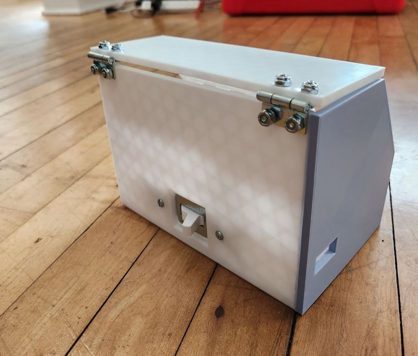
Figure 11: Electrical Housing Final Product (Front) Figure 12: Electrical Housing Final Product (Back)
Testing:
Our first test of the Immersion Circulator successfully passed the majority of our goals; it was able to heat up a bath of ten gallons, reach our maximum temperature, and keep the temperature consistent throughout the bath of water. Over the course of approximately three hours, it reached the 200℉ that we had initially aimed for. In reference to Table 1 provided below, the slope peaked towards the beginning of this test and slowly decreased as time progressed.
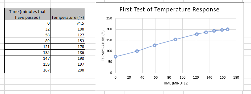
Table 1: Temperature vs. Time of 10-Gallon Testing
The other major test took place with the goal of the immersion circulator heating the bath of water for a consistent 24-hour period. Unfortunately, the temperature logger that was provided to us ended up malfunctioning, which led us to measuring the temperature manually. Temperatures were recorded each hour with an Inkbird Instant Thermometer and displayed both temperature and time. This test went well, as the water was able to maintain a consistent temperature for a 13-hour period and confirm its ability to run for extended durations. During this test no intervention was required and all components not directly exposed to heat remained cool and operational indicating that longer cook times are most likely a non-issue.
Instruction Guide:
- Purchase supplies from BOM.
- Download files from the provided GitHub and OSF repositories.
- Print electrical housing panels and relay cover with a 3D printer.
- Attach back and side 3D housing panels together with gorilla glue.
- Drill four holes in the back panel where you’d like to attach hinges.
- Drill four holes in the top panel where the other holes and hinges align.
- Place the light switch in the allotted hole to ensure fit, but do not screw in until after wiring.
- Place all screws for hinges in.
- Take the extension cable, and take a length of approximately 2 feet from the end with prongs and cut it.
- Separate the wires inside, and strip to expose copper for the green, white and black wires.
- Use the remaining length of cord and the wires inside for the high voltage wire in the project.
- Connect wires between ESP32, the OLED display screen SPI friend, and the Thermocouple amplifier Max31855 as shown in Figure 6. Wire lengths of approximately 4 inches are recommended.
- Connect jumper wires between the ESP32 and each of the 6 buttons as well as between the button’s LEDs and the 12V system as shown in Figure 4
- Connect the wires between the pump, the fan and the 12V power supply as shown in Figure 5. Take care to give enough length of wire such that the fan and the pump will be able to sit a good distance away from the control box, as the fan will need to reach the relay and the pump will need to reach the bath. 2 – 3ft. of wire for the pump is recommended and 18 inches of wire for the fan. The pump should use the high voltage wire as it draws a higher current than other components in the 12V system.
- Using the high voltage wire wire, begin by connecting a short section of wire between one of the prongs of the 12 DC power supply indicated as a transformer in Figure 7 and the circuit breaker. Connect a longer section of high voltage wire approximately 18 inches long to this same node. Secure using solder and wrap exposed connections with electrical tape.
- Connect the other end of the 18 inch long wire to one of the high power terminals of the relay. Cut another length of high voltage wire approximately 3 feet long and secure one end to the other high power terminal of the relay.
- Cut a length of high voltage wire approximately 5 feet long and connect one end to the other terminal of the heating element. Splice the other end of the wire into the black wire of the extension cable plug section and also to the other prong of the 12 DC power supply. Secure with solder and wrap with electrical tape.
- Cut another short section of high voltage wire, approximately 3-5 inches in length and connect the other end of the circuit breaker to one of the terminals on the light switch.
- Connect the Earth ground (likely green wire) from the extension cable plug to the green screw terminal on the light switch. Connect the other open terminal of the light switch to the extension cable plug’s white wire. (Note: white and black wires are interchangeable in this situation due to AC power not having a polarity, however be careful not to mix up either of these wires with the Earth ground, commonly green) Wrap all connections on the light switch in electrical tape.
- Place the light switch into its place and secure it with screws.
- Connect the solid state relay to the heat sink (if not already done) and attach a fan to the side of the heat sink by looping a wire around the heat sink and through the holes at the corners of the fan.
- Position the OLED screen and push buttons in desired locations on the front panel of the electrical casing. Attach these with gorilla glue.
- Cover all metal connections in the electrical casing with electrical tape and/or gorilla glue (up to user’s discretion).
- Note which of the wires on the thermocouple is the “yellow” and which is “red” indicated by plastic sheathing.
- Detach metal coiling from thermocouple (proceed with caution and use gloves to avoid touching fiberglass sheathing underneath).
- Cut and place heat shrinking tubes over thermocouple cables and over the connection between the thermocouple’s metal body and wires. Use a heat gun to shrink and secure the heat shrinking tube. Electrical tape will not suffice for this step, heat shrink tubing or equivalent waterproofing method must be used at this step to ensure the thermocouple is water-proof enough that the thermocouple and a good length of wire may sit below the surface of the water.
- Connect the “red” wire of the thermocouple to the terminal labeled red on the MAX 31855. Connect the “yellow” wire from the thermocouple to the terminal labeled yellow on the MAX 31855. The thermocouple is now wired.
- Begin placing components into the electrical casing. Try to keep giving the MAX31855 as much space as possible.
- Once all components are in the box, glue on the two front panels.
- Warp mesh wire around the heating element in a cylindrical fashion. And place a cap of mesh at the end of the cylinder.
- Attach three hose clamps around the heating element to secure the mesh wire. Place one at the top, one in the middle, and one towards the bottom that also holds on the “cap” to the end of the cylinder.
- Put waterproof adhesive on the top of the water heater and its attached wires (just enough to cover the exposed metal).
- Fill the 10-gallon cooler with water (distilled for best results, using undistilled is likely to produce particulate as minerals boil out of the water near the heating element).
- Attach a strip of Velcro towards the top of the heating element and attach another strip of Velcro to the tank. Additionally, place a command hook upside down on the outside of the tank. Wrap a wire around the top of the heating element and hook it under the command hook, while attaching the heating element by the Velcro.
- Attach a strip of Velcro to the back of the pump and another strip of Velcro to the inside of the tank. Attach the pump by using the Velcro strips.
- Set the thermocouple in the tank.
- Connect a USB C cable between your PC and the ESP32 Metro
- If you do not have the Arduino IDE installed here is a tutorial on how to complete this: Download and install Arduino IDE – Arduino Help Center
- Next we need to configure the ide to download code for the ESP32 Metro. A tutorial on this can be found here: Arduino IDE Setup | Adafruit Metro ESP32-S2 | Adafruit Learning System
- The libraries for the MAX 31855 and the SPI friend are required for the program to compile correctly. To install the library for the MAX 31855 Open the Arduino ide. Click tools -> manage libraries. Search for “MAX 31855”, click install under Adafruit MAX 31855, and click install all dependencies if prompted. To install the library for the Adafruit Bluefruit nRF51, search “Adafruit Bluefruit nRF51” in the library manager and click install.
- At this stage, extract the zip file downloaded from the Github for the Immersion Circulator. In the Arduino IDE go to File-> Open and navigate to the extracted folder. Navigate to a folder labeled ImmersionCirc, open it and open the file ImmersionCirc.ino.
- To switch the ESP32 to programming mode, hold down the button labeled DFU, and hit the reset button near the USB C port
- In the Arduino IDE go to tools-> port-> the port with the ESP32 available.
- Click upload to begin uploading the code
- Once uploaded, click the reset button on the ESP32 again to return to normal operation and disconnect the USB C cable.
- Plug in the device and turn on the light switch for operation.
The Immersion Circulator isn’t measuring the correct temperature?
Occasionally the immersion circulator will not read the correct temperature by a few degrees. With this behavior the temperature will usually be consistently the same number of degrees too high or too low. To remedy this there is a variable in the program called tuningDegrees that will allow you to adjust the reading by some number of degrees Fahrenheit. Simply set the variable equal to the number of degrees to be adjusted by. Connect to the ESP32 via USB C. Place the ESP32 into programming mode by holding the DFU button and then clicking reset. Make sure the correct port is selected in the IDE and upload the code. Click reset and disconnect the USB C cable to return to normal operation. If the relationship between the measurement and the true reading for temperature is not linear it is likely that electrical interference in the control box is the culprit and should be addressed by shortening wires to allow for more room and greater isolation in the control box.
Questions, issues, suggestions or requests can be sent to:
LilyHTheFlower@gmail.com
BOM:
| Part Name | Part Description | Quantity | Location | Price |
| Water Pump | 12v | 1 | Amazon | $9.67 |
| Heater | Heat source | 1 | Home Depot (and most hardware stores) | $10.98 |
| Thermocouple | Waterproof K-type | 1 | Amazon | $10.98 |
| Display Screen | 1.5” OLED | 1 | Amazon | $18.99 |
| Bluefruit SPI Friend | Bluetooth adapter | 1 | Adafruit | $17.50 |
| MAX31855 Thermocouple Amplifier | K-type thermocouple amplifier | 1 | Adafruit | $14.95 |
| Adafruit Metro ESP32 | Single Board computer for controlling circulator | 1 | Adafruit | $19.95 |
| Push Buttons | For control panel | 2, 5-piece sets | Amazon | $15.49 |
| Wire Mesh | Heating Element cage | 11” x 14” | Amazon | $6 |
| Hinges | Electrical casing access | 2 | Local hardware store | $3 |
| Screws | ¼ inch diameter, ½ inch length, for hinges and light switch | 10 | Local hardware store | $0.50 |
| Power Supply | 120VAC to 12VDC | 1 | Amazon | $7.99 |
| 10-Gallon Cooler | Water bath | 1 | Walmart | $24.88 |
| Adhesive | High temp, silicone sealant | 1 tube | ACE Hardware (or other local hardware store) | $13.99 |
| Heat Shrink Tubes | 2.4mm | 20ft | Amazon | $8.99 |
| Large Heat Shrink Tubes | 19.1mm | 4ft (need only a few inches) | Amazon | $7.99 |
| Light Switch | 20A | 1 | ACE Hardware | $6.99 |
| Hose clamps | Holding heater and wire mesh | 3 | ACE Hardware | $3.59 |
| Gorilla glue | Connecting panels of electrical case | 1 tube | Walmart | $5.98 |
| Tubes | For water pump | 3 ft | Amazon | $16.99 |
| Velcro | Attaching heating element and pump to container | 2 strips | Walmart | $3.47 |
| Anti-Skid Pads | For the bottom of the electrical casing | 4 pads | Amazon | $4.25 |
| Circuit breaker | 15A | 1 | Amazon | $14.29 |
| Solid-State Relay w/ Heat sink | 40A, needs heat sink attached | 1 | Amazon | $14.99 |
| Fan | 12V | 1 | Amazon | $13.29 |
| 5V regulator | Vin: 3-4v, Vout: 1.5-35v | 1 | Amazon | $12.19 |
| Thick Cable for Heating Element | Wires for high voltage side | 1 | Amazon | $10.24 |
| Miscellaneous Wires | Wires for 12V and low voltage side | 1 | Amazon | $6.99 |
| Electrical tape | Common electrical tape | 1 | Local hardware store | $1.50 |
| Resistors | 1kΩ, attached across push buttons | 6 | DigiKey | $0.50 |
Links and Resources:
https://github.com/LilyTheFlower/ImmersionCirculator
https://github.com/LilyTheFlower/OpenSourceImmersionCirculatorApp
https://support.arduino.cc/hc/en-us/articles/360019833020-Download-and-install-Arduino-IDE