
Open source hardware project: Restruder
Written by: Renuka Kulkarni and TJ Harikkala
Spring-2023
Introduction
Redesigning the 3D printer extruder to detect the diameter of the filament as it’s fed in and
automatically adjust the feed rate, where the filament is made by recyclebot.
Description and Background
The objective of our project is to design a 3D printer extrusion system to measure recycled filament diameter and automatically adjust feed rate to maintain consistent volumetric flow rate.
Nearly 20% of extruded filament in FDM 3D printing is waste; the Restruder project will allow the filament to be reused after recycling. Commercial recycling/extruding systems that produce filament with highly precise diameters are costly, so we are developing a system that will ensure optimal printing results every time at the extruder. For context, recycling systems made by members of the maker community are typically only able to achieve a diameter tolerance of about ±0.10mm, while newly manufactured filament today typically has a tolerance of ±0.03mm. Restruder will allow greatly improved print quality when using filament with large diameter tolerances.
Goals (Functional Requirements)
1. Device can handle range from Recyclebot
2. The system for measuring the filament width
3. Maintain desired flow
4. The system is made from the controller and stepper motor
5. Design the system without changing the firmware of the printer
Progress
- Literature Review
- Find any existing literature available on similar topics/mechanisms
- Identify any relevant technologies
- Several similar projects already exist in maker community, but require modification of printer firmware
- Found one relevant patent: US 6085957
- Patent citation search: no additional results
- Patent CPC code search: no additional results
- Selection and procurement of parts for initial development
- Design and print enclosure for electronics packaging
- Feasibility Notes
Filament diameter measurement is sensor limited: the optical sensor being used has a practical resolution of 0.02-0.05mm at 1 V/mm, producing a worst-case resolution of 50 mV. The 10-bit ADC of the Arduino Nano is capable of 5 mV resolution.
Using the micros() function and interrupts to read the input signal was observed to result in period measurement accurate to ±6 µs. This yields a percent error of 0.006% at 10 Hz, 0.6% at 1 kHz, and 1.8% and 3 kHz. For context, a 10 Hz signal equates to a stepper output speed of 3 RPM or filament feed rate of 0.21 mm/s through the reduction gearing of the Lulzbot Taz 6 extruder assembly. A 3 kHz input signal produces a stepper output speed of 900 RPM or a feed rate of 64.3 mm/s.
Timer 1 on the Arduino is a 16-bit timer and is implemented with a clock divider of 64; with an on-borad system clock of 16 MHz, this yields a 4 µs timer resolution with a maximum period of 0.5 seconds (minimum frequency 2 Hz) in phase-/frequency-correct PWM output mode.
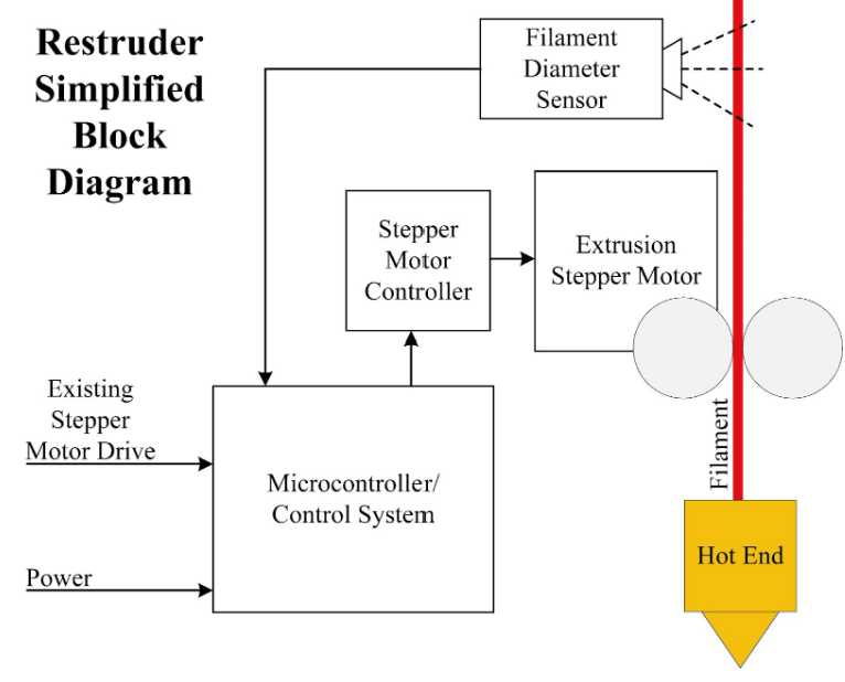
Fig.1 Block diagram
- Software Development
The design requirement preventing printer firmware modification means the stepper drive signals must be read directly by the microcontroller. To achieve this, each stepper drive pair has one of its wires connected to digital inputs 2 and 3 on the Nano through a voltage divider to reduce the 24V drive signal down to 5V for signaling. Inputs 2 and 3 were chosen because these are the only two pins on the Nano that support hardware input triggered interrupts, in this case configured on a change of pin state. The ISR for each pin records the current pin state and time of the interrupt using the micros() function, and sets a flag so additional processing can be done asynchronously in the main program loop.
This additional processing consists of several operations. First, the time between state changes from one pin to another is calculated as a signed value to determine the period of the desired operating speed. The signbit of this delta time value, along with the pin states recorded in the ISR, are used to determine the direction of the stepper motor through digital logic. This direction is directly written to pin 10 for control of the stepper driver. Lastly, the absolute value of the delta time period is scaled for filament diameter error and used to produce the correct output frequency.
Default Arduino functions do not natively support variable frequency outputs, but the stepper driver requires a square wave where each rising edge corresponds to one stepper step; in other words, the speed of the motor is directly controlled by frequency of the square wave signal. To overcome this, Timer1 was manually configured in phase-/frequency-correct PWM mode. This produces an output square wave with a duty cycle of exactly 50%. The output compare register used to determine the period of the output signal is also double-buffered to facilitate smooth, error-free operation while dynamically updating during timer operation.
Project Reproducibility
Currently, the project is implemented on a breadboard to facilitate easy development and testing. A frequency generator and 24 VDC power supply are used to drive a spare stepper driver which emulates the stepper signals the microcontroller will be required to read from the 3D printer. The filament diameter sensor is also connected to the microcontroller on the breadboard. The microcontroller receives 5V power from a laptop and outputs an adjusted frequency and direction signal to another stepper driver, which is supplied 24V from the same bench supply and can be used to drive a stepper motor.
With a physical test system assembled, the microcontroller can be flashed with the appropriate code and a filament diameter measurement system can be purchased and implemented. A filament diameter sensor different from the one we implemented could easily be used due to its output of an analog signal.
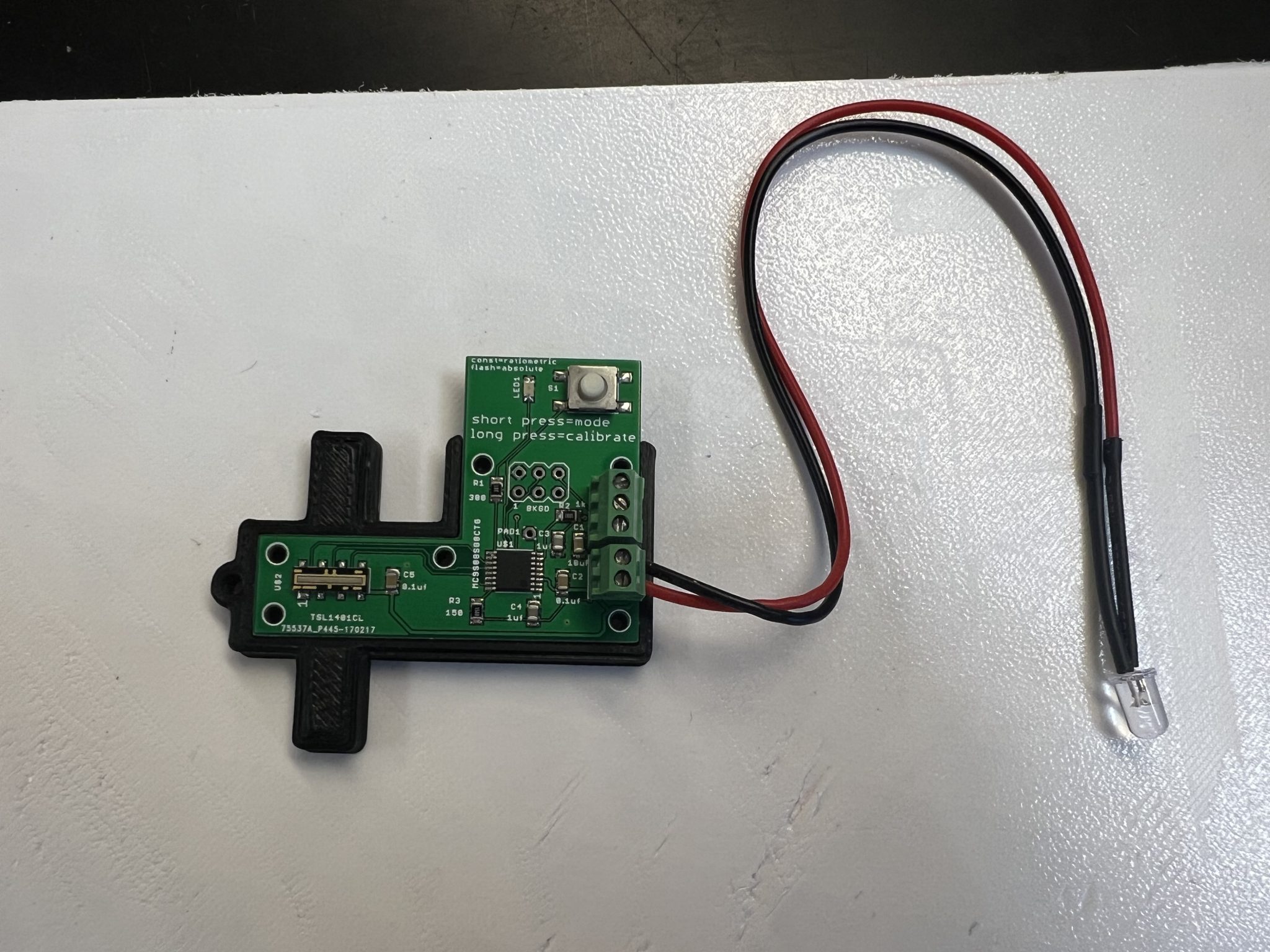
Fig.2 Filament diameter sensor
Open Source Resources Used in Design
| Open source projects related to 3D printer and Arduino | 3D Printer Extruders | Airtripper’s 3D Printer and Arduino Blog |
| Optical filament diameter sensor | https://www.thingiverse.com/thing:454584 |
| Arduino IDE | https://www.arduino.cc/en/software |
Bill of Materials
| Part Description | Manufacturer | MPN |
| Arduino Nano | Arduino | A000005 |
| Stepper Driver | Pololu | DRV8825 |
| Filament Diameter Sensor | https://objectswithintelligence.weebly.com/store.html | |