
Week 2
Research how current can be measured
2 ways:
Older way: Shunt Resistor
- What is a shunt resistor
- how does it work
- why is it the older method
Newer way: Magnetic Sensing using Hall effect sensors or ct’s
- what is Hall effect sensor and how does it work
- how does the current transformer work
- why is it the newer method
Considerations for both:
- can they both measure AC and DC current
- which one is easier to understand (for teaching and documentation purposes)
- which one is easier to implement
- is one method cheaper or more accurate
- what are the disadvantages and advantages
Reference meter used INA219AIDR IC
- which method does this IC use to measure the current
- is this the best IC to use for the meter
- can it do both dc and ac current
Concerns:
How will whatever current measured be communicated and end up on display
Week 3
I was able to form an understanding of measuring current using a shunt resistor and researched the INA219AIDR IC. I need to continue forming an understanding of hall effect sensors to make a more informed opinion on which method would be best to use.
To Do:
Newer way: Magnetic Sensing using Hall effect sensors or ct’s
- why is it the newer method
Considerations for both:
- which one is easier to implement
- what are the disadvantages and advantages
Concerns:
How will whatever current measured be communicated and end up on display
Week 4 update
I made some good progress in understanding the INA219. I created a schematic and the shunt resistor circuit, in the datasheet they provided the optional implementation of an input filter circuit that I will consider adding to the schematic if necessary. I continued researching how to program the IC for different max expected currents and shunt resistances. Programming an ic is new to me especially using C++, but there is a good library on Arduino that I found. I will continue creating pseudo code necessary for the program if I include that library.
To-do list-
Get a final shunt resistance value. This will depend on how confident I feel that I can change the default shunt resistance the IC uses. After that is determined document the resolution of the current being measured and the range. By determining this I will build documentation of how the IC actually converts the current internally and how the code does so using current_LSB, PGA, etc.
My biggest Concern:
is actually making code that will compile. I feel confident that I can create code that should work but should I run into an issue, a minute detail I miss, I fear I would not be able to figure out why.
Week 5 update:
Finalized current sensing details and determined LCD screen with i2c adapted would be best for displaying measurements.
To list:
Research how i2c adapter module should be connected to LCD screen
transmissible or transflective LCD
how will the combination be added to the final board
research code for displaying the measurements (find library)
understand the implementation of code create pseudo code
Project 5/Week 6:
Successfully tested current measurement with Eval board.
Decided we would use LCD without I2c Adapter, and we are using the Adafruit transflective screen
Researched LCD library on Arduino without i2c
Researched how LCD screen connects to Arduino and where those go to the microcontroller for coding and building the schematic
Finishing PCB design as a group this week
Project 6:
Almost finished with PCB design:
Need to: connect traces and add resistance measurement
Look at example multimeters and try to replicate their circuit
Project 7:
I was able to begin getting the code done for the multimeter
Much of it was understanding how Arduino IDE works and researching how other people have coded multimetes
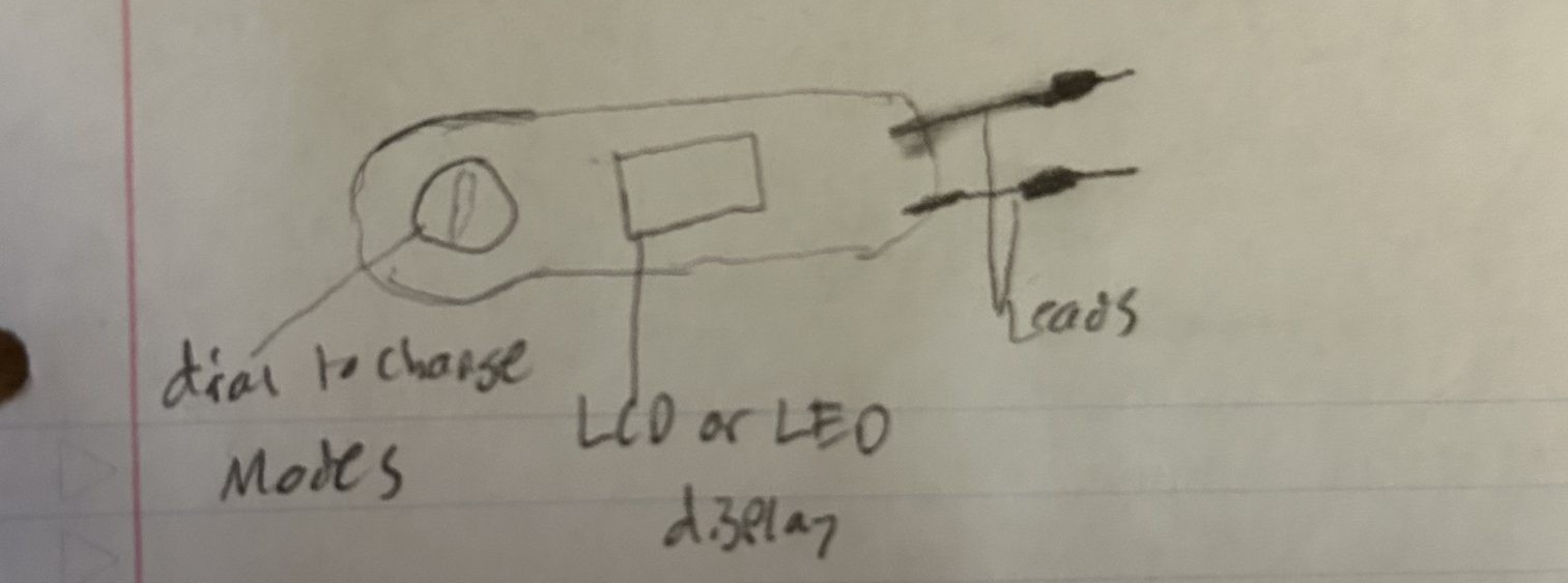
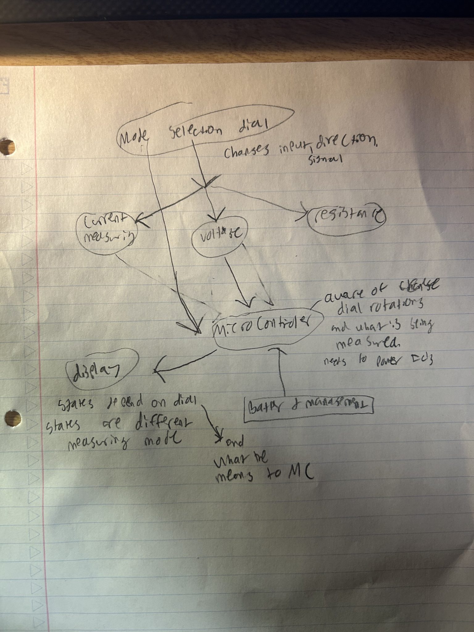
the plan for this week is to get the mode switching mechanism coded up
figure out if we need to do any delays
initialize the pins on the microcontroller
work the code for the external adc does library have as seemless i2c and overall library
work on creating checks throughout the code using serial monitor
Project 8: I successfully displayed accurate current values on an LCD screen.
I continued updating our code, adding comments, logic for changing measurements, and executions for displaying
this week I need to talk to Caleb, James, and Luc on what they have done with the code and what they would like still done. I need to verify their voltage measurement code is working properly and luc’s work on the setallinputs method. I will also help put the board together.
Project 9:
Multimeter is working perfectly except for some deviations on voltage measurement. Code is functioning good and we are getting measurements for both current and voltage.
This week I plan to work with peter to figure out why this is happening and possibly add code that alters the measurement. Hopefully, through comparing a lot of different measurements to the fluke and plotting the measurements I will be able to discover a pattern. Maybe I can create a function that maps our measurements to the correct value or in certain voltage measurement ranges a certain scaler is needed, or possibly something in the ADC was incorrectly set in the code. I also think they are some methods in the ADC library for checking its function. I have started documentation as well.
Project 10:
I created code for autoscaling current measurement. The code checks the current being measured and continuously lowers the pga to get higher resolution currents if there are lower amounts of current measured and it is within range of the maximum shunt voltage that can be measured. It is not necessary but it does give more specific measurements. The next step is finishing the documentation.
Project 11:
The Report draft was finished last week, now I must begin working on the report. I would like to be a little clearer on how the INA works. I would like to describe in helpful detail to future users the current measurement side of things.