Background and Problem Statement:
Modern water filtration systems used in residential pool applications require the user to balance and maintain the chemical properties of the water within the system. Unmaintained or unbalanced water causes systems to run inefficiently, or, in extreme cases, the water can damage heating and filtration systems. To maintain and balance the water, the user must determine the water’s sanitizer concentration, acidity, and alkalinity, then add the necessary chemicals if correction is needed. In residential systems, this process must be manually completed by the system user.
Vision
This project aims to create an open-source system that automates the chemical balance for residential pools. The final product itself will be relatively low maintenance and non-invasive to the existing filtration and heating system. This will be achieved by keeping the project separate from the existing pool system so that it can be implemented in a location that is both accessible and out of the way.
Fall 2022 Goals
- The entire device will have design files originating entirely from free and open-source software.
- This goal was completed
- The device shall read and interpret the chemical composition of pool water
- This goal was partially achieved as the sensor was able to take color readings, however, the movement of the strip meant that the sensor could not accurately detect the edges, and therefore could not parse the data accurately.
- The device shall respond according to the above reading to correct the composition of the pool water
- This goal was partially achieved. The device was able to collect the data and parse it into a table but was not able to compare it to nominal values. The code for a lookup table has been integrated and the code to compare the measurements with the established values is written but the lookup table has no values yet.
- The device shall be able to accurately and controllably dispense chemical powders
- This goal was completed. The dry mover subsystem dispenses .85 grams per 10 revolutions with a standard deviation of +-.02 grams. This equates to a relative standard deviation of 2.79%.
- Any custom part in the device shall be entirely 3d-printable
- This goal was completed. All custom parts have been designed and are toleranced to be printed on a consumer-grade FDM 3D printer.
- The device shall pre-mix and dissolve the powdered chemicals before dispensing them into the pool
- This goal was partially achieved. Revision 5 of the mixer successfully pre-dissolves around 90% of the dry chemical with the pump running at full speed. Further refinement was implemented but not thoroughly tested.
- The device shall safely contain chemicals
- This goal was completed. The containers are made out of PET plastic and create an air-tight seal when closed.
- The device shall have easily accessible locations for chemical refilling
- This goal was completed. The chemical containers are located on the top of the device for easy access.
- The device shall be waterproof
- This goal was completed. The box and power jack are IP67-rated. All other connections are sealed using weather-resistant silicon on both the inside and outside of the housing.
- The device shall be self-contained
- This goal was completed. The entire system rests in the housing or is attached to the outside of the housing.
Fall 2022 Value-Added Goals
- The device can have a custom PCB for easy assembly
- This goal was not completed
- The device can be “put to sleep” and run on low-power consumption
- When the door to access the color sensor is closed, the device is in a “do nothing” phase where it waits for the door to be opened. It consumes less power in this way, however, it does not utilize the “low-power” mode of the Arduino mega.
- The device can be easily moved
- In addition to being self-contained. The device can be easily picked up and moved without any damage to the internal components.
How to Build
Bill of Materials:
| Part | Price | Quantity |
| Food storage containers | $2.97 | 4 |
| Flexible Tubing | $5.60 | 4 ft |
| Drill Bits (5/16) | $5.99 | 4 |
| Silicon Sealant | $5.99 | 1 tube |
| Water Pump | $29.99 | 1 |
| Adafruit Color Sensor | $19.95 | 1 |
| PETG 3d printer filament | $19.99 | 1 kg |
| Stepper motor (set of 6) | $13.99 | 1 |
| Arduino Mega | $20.99 | 1 |
| Waterproof Enclosure | $35.99 | 1 |
| Relay module | $6.79 | 1 |
| Pool Test Strips | $22.49 | 1 |
| 12V power supply | *$10.00 | 1 |
| Reed Switch | $6.99 | 1 |
| Flexi Arm | $10.95 | 1 |
| Waterproof Barrel Connector | $12.99 | 1 |
| DC Motor Controller | $9.99 | 1 |
| M2 bolts | *$1.00 | 4 |
| M2 nuts | *$0.50 | 4 |
| M4 bolts | *$1.00 | 8 |
| M4 heat inserts | *$1.00 | 8 |
| 2-Part Epoxy | $3.97 | 1 |
Parts to Print:
| Name | Qty |
| Acceptor | 1 |
| Bit Adapter | 4 |
| Color Mount | 1 |
| Door | 1 |
| Dry Mover Top | 4 |
| Dry Mover v4 | 4 |
| Mixer v5 | 1 |
Assembly:
Acquire off-the-shelf components as outlined in the above bill of materials. Print all parts off of the above print list using PETG filament.
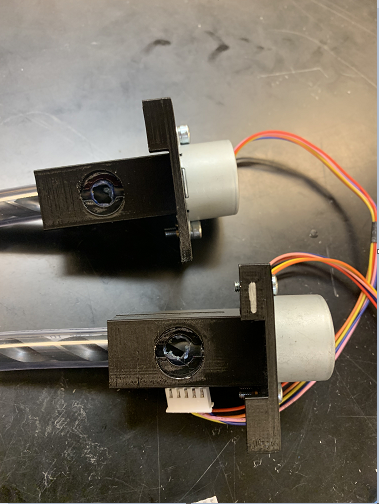
Dry Mover Subassembly
- Using an angle grinder, cut all four drill bits down to 87 mm
- Using a bench vice, press the bit adapters into the newly cut bits
- Press the bit adapter onto the motor making sure the motor shaft fully seats into the adapter.
- Use a soldering iron to set the heat inserts into place on the dry mover parts
- Using m4 bolts, screw the assembled motors into the dry movers
- Add this assembly to the motors to part using heat inserts or nuts and m4 bolts
- Cut 4 60 mm long sections of ⅜ ID tube
- Straighten this tube using a heat gun if necessary
- Install the tube into the dry mover assembly as shown
- Using a marker, mark the area hole that needs to be made at the top of the tube
- Cut the tube using a chisel-tipped soldering iron set to 325 c, and clean up using a 10 mm drill bit on a low-speed drill
- Reinstall the tube into the dry mover assembly, making sure the hole in the tube lines up with the hole in the printed part
- Add a small amount of glue to the edge of each side of the mover to prevent the tube from turning when the bit is actuated.
- The assembly is printed with two support tabs on top. Using a bench vise, remove the left tab from two of the dry movers and the right tab from the other two.
Enclosure Subassembly
- Using a 3 mm drill bit, drill through the third stud from each corner on the closure and hinge sides of the enclosure
- Drill through the center of each of the 4 storage containers using a 3mm drill bit
- Center the support board onto the bottom of the mixer, mark through the studs and drill a 3 mm hole at each mark
- Using 4 40mm M4 bolts, fasten the containers, support board, and housing together.
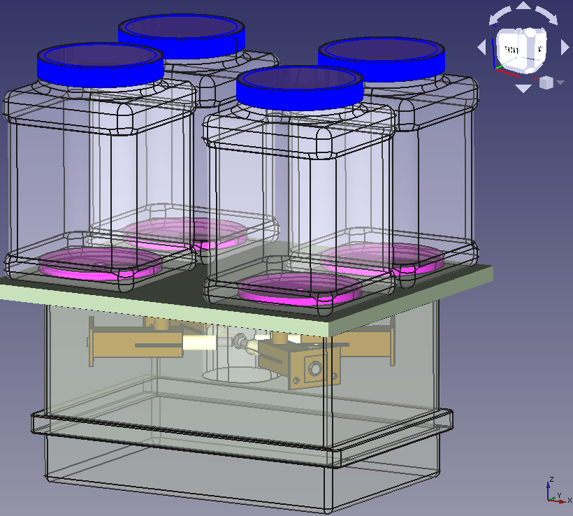
Mixer Subassembly
- Glue the mixer top to the top of the exit tube inside the mixer
Dry Mover/ Mixer installation
- Press the 4 mixer tops into the dry mover assembly
- Fit the four dry movers into the mixer
- With the dry movers in the mixer, turn the mixer upside down and place it into the enclosure.
- Center the mixer in the enclosure and slot the 4 mixers in place between the corner studs in the enclosure
- Ensure the backs of the dry movers, dry mover tops, and mixer are all sitting flush against the bottom of the enclosure
- Using a small amount of hot glue or a marker, tack or trace the dry mover tops and mixer in place
- Remove the dry movers and mixers, leaving the mixer tops in place
- Drill a 10 mm hole through the center of each dry mover top going through the bottom of the enclosure, support board, and storage containers
- Remove the dry mover tops
- Glue the dry mover tops in place using enough glue that a seal is created between the parts and the housing
- Using silicon sealant, seal the four ⅜ ID tubes into place in the mixer
- Apply glue and silicon sealant to the top surfaces of the dry movers and mixer, and silicon sealant around the top of the mixer
- Install the mixer and dry mover into the enclosure ensuring there is a good seal between the top of the mixer and the enclosure
Plumbing and I/O
- Mark 15 mm down the ⅝ ID tubing
- Using a 5 mm drill bit, drill two holes opposite each other on the 15mm line
- Using silicon sealant, install the tubing into the bottom of the mixer making sure the holes in the tube are aligned with the relief holes in the mixer
- Using silicon sealant, install the ⅝ ID tubing onto the mixer inlet
- Clamp the inlet tubing in place with a zip tie to prevent leaks
- Drill 20 mm and 8mm holes on the hinge side of the enclosure as close to the sealing edge as possible.
- Feed the corresponding tubes through; seal with silicon sealant
- Drill a 4 mm hole, feed the pump wire through, and seal with silicon sealant
- Using a rotary tool, cut a 12 mm square into the opposite (closure) side of the box, 35mm from the sealing edge and 80 from the right side of the enclosure
- Using silicon sealant, install the strip acceptor housing
- Drill a ½ inch hole 70 from the sealing edge and 65 from the right side of the enclosure
- Using silicon sealant, install the waterproof connector
Prepare the color sensor assembly
- Glue the two rare earth magnets into position in the door
- Put the door in place; position the third magnet in place inside the enclosure and glue it in place
- Using M2 bolts and nuts attach the color mount to the color sensor, ensuring the sensor and onboard LED can be clearly seen through the hole
- Install the color mount and sensor into the strip acceptor; center and glue in place
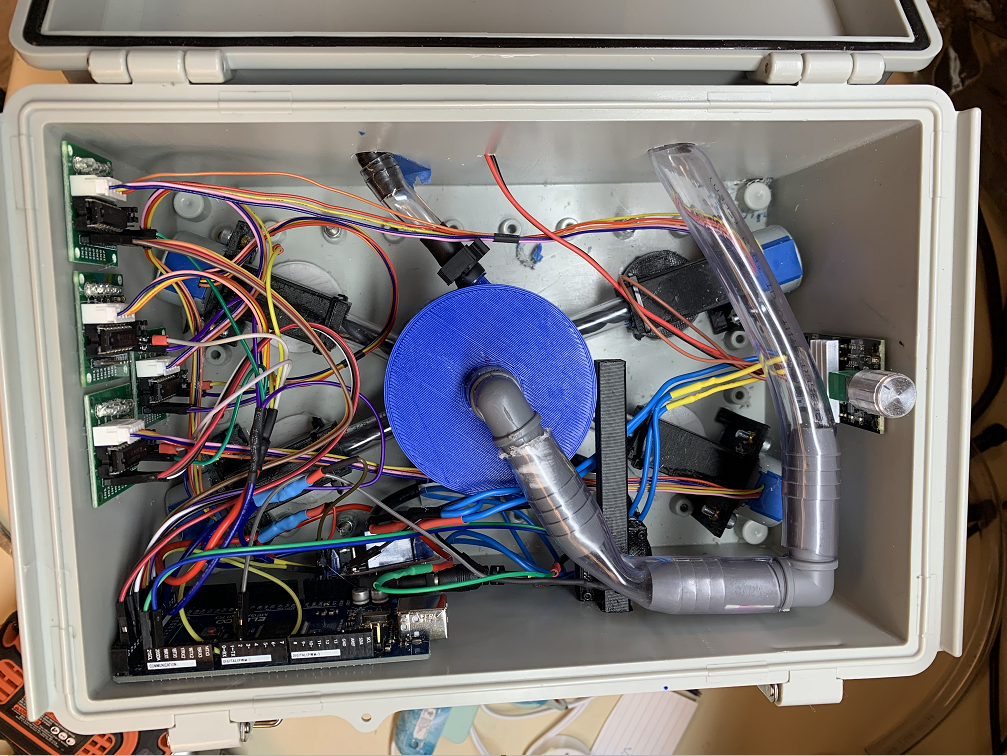
Component placing
- With the system resting on the tops of the storage containers and the hinges furthest away from you, glue the four motor control boards on the left wall
- Glue the motor controller to the right wall
- Glue the reed switch behind the second magnet in the door
- Glue the Arduino against the left corner of the closure side
- Glue the relay under the Arduino
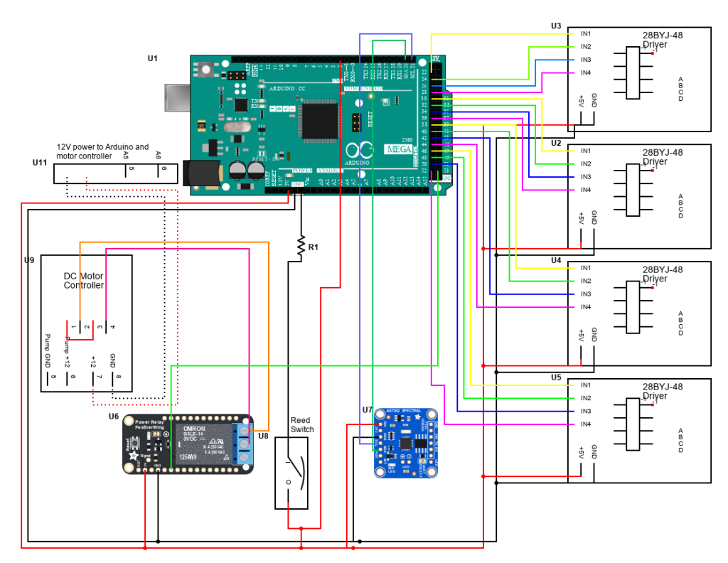
Wiring
- Prepare cables to run power to each of the components in the device as shown in the schematic. Run +5v and ground to each of the control boards, reed switch, relay, and color sensor
- Run +12v and ground to the pump motor control board
- Temporarily power up the pump motor control board with the pump connected
- Find the lowest power setting that the pump can operate at while still starting consistently
- Wire the rest of the components according to the wiring diagram
System Calibration and Code
- Upload the “LookupTableFillCode.cpp” to the Arduino mega.
- This code takes 10 color measurements and averages them out, then prints them to the Serial Monitor on Arduino IDE. The baud rate is 38400.
- Insert the unused test strip fully into the strip acceptor. Wait for a few cycles of data until the data stabilizes. This will be the values of the “white” of the strip.
- Change the WHITE array on line 76 of the code to reflect the values being read. Re-upload the code
- Ensure the “Distance from white” printout is a low value ( <5 ).
- Open up the “PoolSystemCodev2.cpp” and copy over the new WHITE array values into the WHITE array in function “isWhiteDistance” (line 84)
- Upload “PoolSystemCodev2.cpp” to the Arduino.
Using the Device
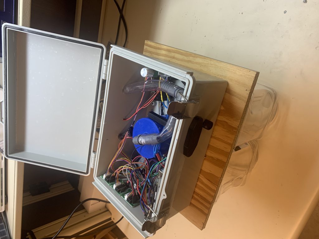
- Set the device on the side of the pool with the 12V power connector plugged in.
- Dip the pool strip into the water and wait for a few seconds for it to be stable.
- Remove the door covering the strip acceptor.
- Insert the strip slowly until it reaches the back of the acceptor, then pull it out again slowly.
- Replace the door over the strip acceptor.
- The device should now have read the information from the strip and be responding accordingly. Nothing else is required.