
Open Source Open Platform Quadcopter
Spring 2022-Fall 2022
Joaquin Ganoza – Mechanical Engineering
Christopher Hettinger – Computer & Electrical Engineering
Dr. Shane Oberloier – Enterprise Advisor

Michigan Technological University
Open Source Hardware Enterprise
Houghton, MI 49931
Table of Contents
I. Previous Year Summary
II. Acknowledgements
III. Introduction
IV. Objectives and Constraints
A. Objectives
B. Constraints
V. Project Planning and Timeline
VI. Project Budget
VII. Concept Design with Inspire
A. Frame Optimization
B. Infill Density Study
C. Conducting Optimization on Existing Design
VIII. New Component Design
A. Center Chassis
B. Arm Design and FEA
C. Manufacturing Components
IX. Electrical System Modifications and Sensor Additions
A. Overview
B. Flight Controllers, GPS, and Power Terminal
1) Flip Mega 3.5 and MATEKSYS F405-miniTE
2) MATEKSYS M8Q-5883 and Power Distribution
C. Sensor Additions
1) Arduino Nano
2) I/O Board
3) OpenLog
X. Conclusions and Future Work
XII. Appendix
Appendix A: Assembly BOM
Appendix B: Electrical/Mechanical Hardware Assembly Procedure
Appendix C: Programming/Software Procedure
Appendix D: PETG Material Properties
Appendix E: Wiring Diagram
Appendix F: INAV Configurator Settings
Appendix G: Links
I. Previous Year Summary
Originally, the Open Source Cinematography Quadcopter Project was created and completed by Dylan Mercier, Joaquin Ganoza, and Harris Neill. The original intent of this project was to design and build a quadcopter for cinematography using 3D printed components, low cost consumer electronics and an Arduino Uno programmed using MultiWii. The current project sought to improve upon the original project by optimizing the frame design to minimize weight while maintaining structural integrity, as well as by adding plug and play support for numerous sensors to allow for a variety of data collection applications. Thus, the new project is named Open Source Open Platform Quadcopter.
The previous year was left off with the completed Open Source Cinematography Quadcopter as a baseline for the further redesign to adapt for the new incoming peripherals. The drone was designed around the ability to capture video and photography while also being able to handle an appropriate payload. Given such parameters were met, the main mechanical components such as the Electronic Speed Controllers, Motors, and Radio transmitter are all intended to be utilized in the Open Source Open Platform Quadcopter with the changes being made in the central computing system, in this case replacing an Arduino microcontroller with a Flip Mega 3.5. This board eliminates the need to have an external IMU and also introduces the ability to have a built-in GPS to the system. This new board is compatible with the old software and code utilized to control the Cinematography Quadcopter, so only minor changes will have to be made for seamless use between current GUIs and control methods.
When it comes to the mechanical design of the drone, a full redesign was conducted in order to properly adapt to the new peripherals and goals set for the project. Originally an open source CAD software, FreeCad, was utilized to build and conduct FEA on the components of the drone. For this redesign, Altair’s new software Inspire was chosen as the software to be utilized as it comes built in with optimization features that allows for the user to set design goals for the software to follow. In this case, known loadcases were calculated such as thrust and torque capability to set as the design parameters for the software to conduct a material optimization.
II. Acknowledgements
The Open Source Open Platform Quadcopter team would like to thank those involved within the Open Source Hardware Enterprise for the opportunity to continue this project and the collaborative efforts that were brought forth during this redesign. The team would also like to thank Dr. Shane Oberloier for his guidance in this project and allowing us to maintain an obtainable scope for the drone in the given timeframe. I, Joaquin Ganoza, would also like to personally thank my partner John Hettinger for his collaborative efforts in the project given the semester difference and in preparation for final testing this upcoming Fall semester. I would also like to thank Erik Larson from Altair as he provided guidance on the proper use of the Inspire software to approach the optimization of the new components. I, John Hettinger, would like to thank Joaquin for his work on the chassis redesign, as well as his continued guidance throughout the fall semester as I completed my portion of the project. I would also like to thank our advisor, Dr. Shane Oberloier for his guidance and assistance with this project.
III. Introduction
The initial choice for a redesign on this quadcopter was to mechanically achieve a more user-friendly platform as the prior design was based on the concept of cinematography. While conceptualizing the new design, we sought out to make the drone also adaptable to various forms of peripherals that could be added at a later date. With this in mind, the Mechanical team focused on keeping the original structural integrity that the Cinematography drone has all while reducing the overall mass of the unit. Since mechanically the team was retaining the hardware such as the Motors, ESC, and Batteries, it was understood that the weight reduction had to be done on the 3D printed components of the frame. This is where the utilization of Inspire comes into fruition to achieve a specific weight goal set by the team, in this case being reducing the overall 3D printed mass to 50% of the original Cinematography Drone. Additionally, the Electrical/Programming team was tasked with replacing the Arduino Uno flight controller with a MATEKSYS F405-miniTE flight controller and adding and programming an Arduino Nano for sensor I/O and control. This team also worked on programming the new flight controller to work with all of the existing hardware and adding programming for GPS as well.
IV. Objectives and Constraints
A. Objectives
The overall goal for this project was to deliver a new quadcopter frame designed that retained original integrity standards set by the Cinematography team while providing a user-friendly chassis for optimal multi-peripheral use. Utilizing 3D printed components allows for open source users to recreate and modify the design to their own liking, fitting the ideology that the Open Source Open Platform team strives for. Here are the goals set for this project:
- Open-Source Part Files for Modification
- While the Inspire software is not open source, components will be saved in appropriate file types that can be utilized in open source CAD software such as FreeCad.
- Open-Source controller hardware
- New iNAV based flight controller, MATEKSYS F405-miniTE.
- Allows the community to use different styles of iNAV supported flight controllers for functionality.
- Arduino Nano for sensor control/data acquisition and logging.
- 3D Printed Components
- Allows for low cost manufacturing of new and existing components
- Relatively quick print times with new generation printers allow for constant iteration on new designs
- Perform basic quadcopter flight maneuvers
- Ability to be controlled from a handheld transmitter.
- Take off and land safely.
- Precise and accurate controls.
B. Constraints
The constraints of this project have not deviated from the original Cinematography Quadcopter design, with only a few changes being made regarding the open source CAD software being utilized in the design. Here are the limitations placed to keep the design accessible to any open source enthusiast:
- Open-source tools will be used to manufacture the frame of the quadcopter
- 3D printing will be the basis of manufacturing for this project, as it allows almost any user to manufacture the frame of the quadcopter
- Must be able to withstand forces both during flight and during an uncontrolled landing
- Every component needs to be covered and the quadcopter needs to be water-resistant in the event of inclement conditions during flight or landing
- Reduce cost to under $550 for final product minus testing equipment.
- Complete the project within a 2-semester time frame.
- Follow FAA regulations.
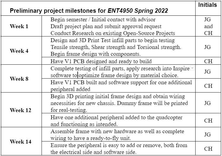
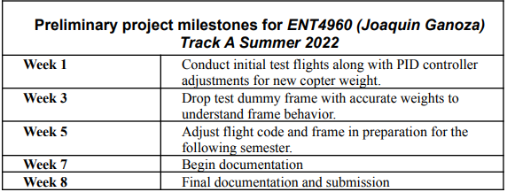
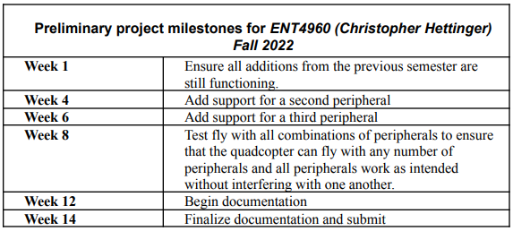
V. Project Planning and Timeline
The project’s timeline can be found in the table below, illustrating how the project is going to be conducted across the next year. This timeline was designed around the assumption that all hardware for flight capabilities would arrive on time which did not occur, so changes had to be made for the Summer and Fall semesters.
Project Start (Joaquin and Christopher): January 17th 2022 (Semester I)
Project Completion (Joaquin): June 30th 2022 / (Christopher): December 9th 2022 (Semester II)
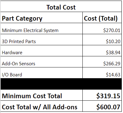
VI. Project Budget
The estimated cost of the Open Source Open Platform Quadcopter can be found below. The BOM is split into two costs; one for the minimum cost of the quadcopter for just flight with no add-on sensors and one that includes the cost of all add-on sensors and associated components. This BOM only includes component sections, while Appendix A has another copy of this BOM in addition to BOMs that break each component section into the components needed. These BOMs don’t include the entirety of money spent on the project since it excludes costs of test electronics/hardware and electronics/hardware that were replaced. The minimum hardware stayed mostly the same beside the replacement of the Arduino Uno R3 for the MATEKSYS F405-miniTE as the new flight controller as well as any add-on sensors and I/O board components.
VII. Concept Design with Inspire
A. Frame Optimization
When it came to the frame, the original design was built without weight optimization in mind. This next iteration focused on reducing the existing drone weighing in at 1kg to a more acceptable weight of 500-750g. Originally, the goal was set to follow FAA standard of Sub-250g recreational drone, all while still following regular flight procedures but simply allowing for an enthusiast to build and fly a drone under the 250g weight limit without the need for registration. With the current hardware that is being reutilized the team realized that achieving a sub-250g overall weight would have to be done with a different combination of motors, esc’s and battery since those components alone weigh in at about 500g. The approach for the new prototype frame began with a study of infill density in extrusion printed 3D material, focusing on material properties of PETG.
B. Infill Density Study
The infill density study was designed around ASTM D638-14, which is formally known as Plastic Material Tensile Test. These tests allow for understanding of how the material properties vary as infill density within a structure varies, in this case being wall thickness in a generic square-pattern infill. Figure and Table 1 below illustrates the Tensile Testing conducted and the results for the tests.


Figure 1: Tensile Test in Progress
Table 1: Infill Density Properties of PETG
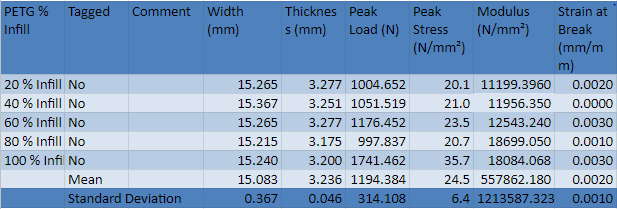
The initial infill density study illustrates a significant difference in how infill density affects properties of the material, in this case being the modulus and peak stress capabilities of the material.
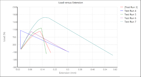
Figure 2: Load vs Extension on PETG
C. Conducting Optimization on Existing Design
Following this testing, initial design of the proptype frame began through the use of Altair’s Inspire program. While not necessarily being open source, the parts designed through Altair will be exported as .step files for modification if a user decides to change any parameters. The driving reason to utilize Inspire is for its material optimization capabilities through loadcase parameters. This is a different form of modeling that aims for the user to provide the software with general shape and design parameters of their choice and the software takes that information into account for minimizing material. Since an original frame has been designed prior, the arms of the airframe were utilized in this process.
To start the optimization process, a factor of safety for airframe components had to be determined. Following ASME standard, an aircraft component should have a minimum FOS of 2.5 so that is what was utilized within the optimization. Followed by the FOS, design space must be pre-determined in order for the software to know what volume of the component is allowed to be reduced. In this case the design space parameters were determined to be the mounting points of the arms to the mainframe and the mounting points for the motors, illustrated in Figure 3 below.
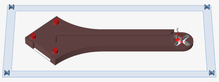
Figure 3: Design Space Areas (Red)
Following the establishment of design parameters, correct material properties were assigned to the component for the optimization software to use in its material reduction calculations. This is where the prior infill density study will come into play when an optimal infill density is selected to use for the component and it will allow for the software to conduct a more accurate optimization. The goal in the coming semesters is to take this application and test the optimized arms to compare FEA conducted within Inspire to real world testing in the Tensile and 3-point bending test. After the parameters are set up, optimization can begin on the component.
Figure 4 below illustrates the optimization structures Inspire generates with the provided loadcase, FOS and material properties of PETG. A key part of the optimization is indicating which manufacturing process is going to be utilized for the component so the software makes it actually machinable. The initial component is just a structure generation that the software creates, where post processing must be conducted to create a smooth and final-print ready component.
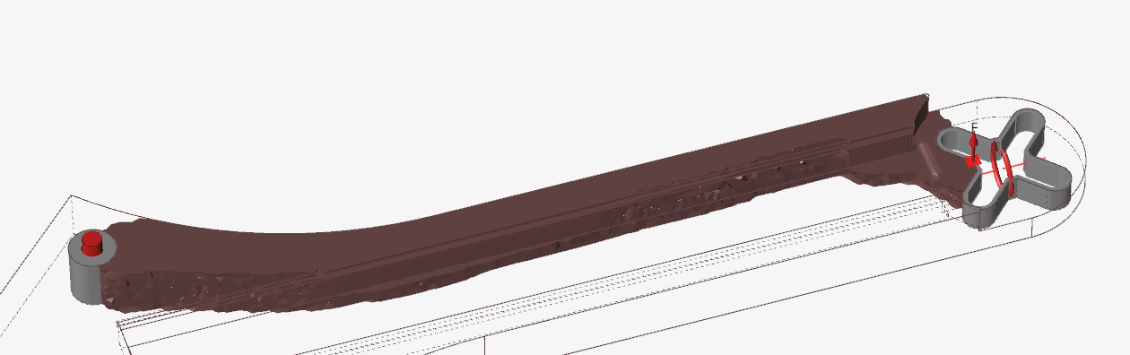
Figure 4: Structure Optimization
Figure 5 below illustrates the initial prototype arm through the optimization characterized by Inspire with post processing structure added. This optimization utilized a loadcase containing motor thrust and torque at maximum operating conditions to stimulate the most stressful test case for such. In the coming months optimization on this component will continue with the intention of calculating worst-case loadcases for a freefall from operating height to a lateral collision with an immovable object.
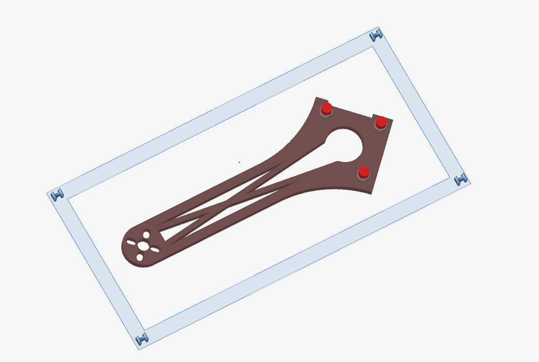
Figure 5: Initial Prototype Arm
This testing was mainly conducted to understand how the AI software interpreted the provided loadcases and utilized them to remove material to reach the indicated FOS. Compared to the original FEA testing conducted by the previous mechanical lead, this component is built to the same integrity standards and can be utilized on the existing frame while reducing the overall mass by 15g or 30% that of the original.
VIII. New Component Design
A. Center Chassis
When it came to designing the new chassis, focus was firstly placed on the center chassis. Developing the center chassis as one whole unit allows for ease of assembly and access to all wiring components contained within the unit. One of the other goals set for this new center chassis was the ease of adding peripherals externally as it is intended to be an open platform and adaptable unit. Another important component of the center chassis is an isolated compartment for the battery being utilized in the drone. This allowed for the elimination of utilizing a battery strap to hold the battery in place and gives the

Figure 6: Center Chassis

Figure 7: External Wiring into center chassis
This new chassis design, compared to the original, eliminated the need to take apart the entire drone to replace a single arm or introduce wiring from the ESC’s into the internal components. Along with becoming an easier to assemble component, the center chassis compared to the original shed about 150g. Another area of improvement of the new design was the ability to keep all the hardware and wiring out of the elements and contained within the center chassis. This was simple for the main components housed within the center chassis, but needed action on the wiring that came from the motors to the ESCs and lastly to the center to connect to the Flip Mega 3.5. This is further discussed in the following section: Arm Design.
B. Arm Design and FEA
When beginning the new design of the drone arms, a large challenge was faced in the form of developing a component that maintained the initial integrity while housing all wiring and electrical components inside. These integrity standards were set by the previous mechanical lead that illustrated the forces expected during operation along with FOS calculations. With the new arm design, it was sought to use such load parameters along with newly calculated forces such as torque produced by the motor and prop and a simulation of a worst case crash from a given altitude.
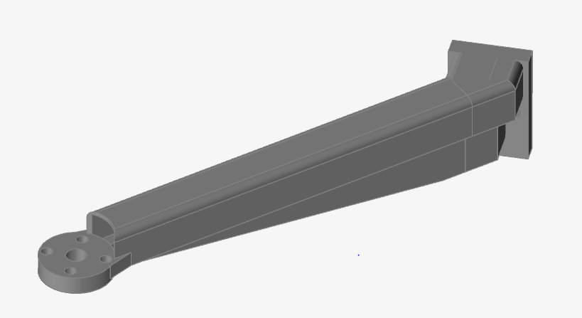

Figure 8: New Arm Design
Figure 8 above illustrates the new design for the arm component of the Open Source Open Platform Quadcopter. This design follows the same geometrical balance as the previous drone of a symmetrical x-copter but adapted to fit the longer center chassis designed prior. Maintaining the x-copter design allows for even distribution of the load across the whole chassis when assembled and provides internal channeling for the ESC and Motor wires to be housed within, fulfilling the need to contain the hardware inside the drone and away from the elements.
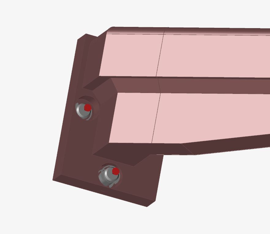
Figure 9: Joint Placement for laid Analysis
When it comes to the technical data utilized to develop the new arm, several loadcases were considered during various optimizations. Before applying loadcases, the structure needed joints assigned to depict how it would be mounted in the chassis, depicted by Figure 9 above. The first was the maximum thrust capable by the motor and propeller combination, in this case 15N of capable thrust per motor and propeller combination. The second was the torque produced by the motor and propeller on the arm relative to the mounting points on the chassis, in this case being 2.49 N-m. Finally, a worst case scenario loadcase was determined to simulate the aircraft falling out of the sky and reaching a close to relative terminal velocity, experiencing an impact force of over 100N. This impact force was utilized to identify and design around the intentional breaking points of the component to make replacing it a simple task and avoiding having the issue lie within the center chassis break under such conditions. Figure 10 below illustrates the arm under testing loads with the before and after shadow enabled:

Figure 10: FEA of Arm under Thrust and Torque Load
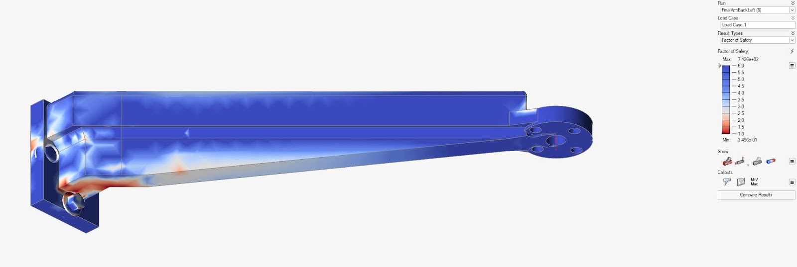
Figure 11: Factor of Safety Analysis
Figure 11 above depicts the factor of safety spread across the component relative to the thrust and torque loads. The optimization was given a factor of safety of 2.5 to achieve, illustrated on the figure above as the red areas whereas the blue and white areas indicate areas where the FOS is higher. The peak working stress obtained during the FEA testing on the read areas reached 20.562MPa, with a UTS of 53MPa indicating that the calculated FOS of this arm to be 2.57.
C. Manufacturing Components
To manufacture the components, a traditional 3D extrusion printer was selected as the tool to produce the center chassis, cover, and arms of the Open Source Open Platform Quadcopter. Previously utilized to manufacture the cinematography drone was the 3D printers located in the OSHE enterprise laboratory, the Lulzbot Taz 6. While this printer was capable of producing the previous components, it struggled to produce quality results of the arm as it carries a unique design with overhang angles that exceed the specifications of the Lulzbot Taz 6. Given that the newly designed arm is hollow to carry the wiring of the motor and Electronic speed controllers, support material could also not be utilized within the part as it would be impossible to remove after production. To attempt and work around these issues, various methods of print setups were utilized to attempt and obtain quality prints.
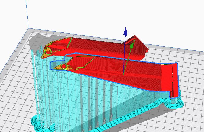
Figure 12: Angled Component for Printing
Figure 12 above depicts the angles necessary to print on the Lulzbot Taz 6. Not only is this printing style non optimal for material use, but also produces the components with layers parallel to the direction of the Thrust force being placed on the end of the arms. This inherently makes the component weaker and strays it further away from the FEA conducted on the solid part. In order to produce the components to the standards required for the design, use of a different printer had to be incorporated to produce quality components.
Figure 13: New Printing Layout
To accommodate for a new printing layout with aggressive overhang angles, a new printer was introduced to be utilized for manufacturing: The Ender 3 V2. This is also a traditional 3D printer similar to the Lulzbot Taz 6 but differs in important ways that allow for the quadcopter arm to be printed without utilizing support material internally. The Ender 3 V2 is capable of printing aggressive overhang angles along with having a larger bridging distance capability compared to the Lulzbot Taz 6. Bridging in this case is when the print nozzle is capable of printing across one side of the component to the other without having support material under it. This was key as understanding the bridging capabilities of the Ender 3 V2 was what led to the production of adequate components that also meet integrity standards. Figures 13 and 14 illustrate the new setup for printing the quadcopters arms where the bridging and linearity of the print is shown.
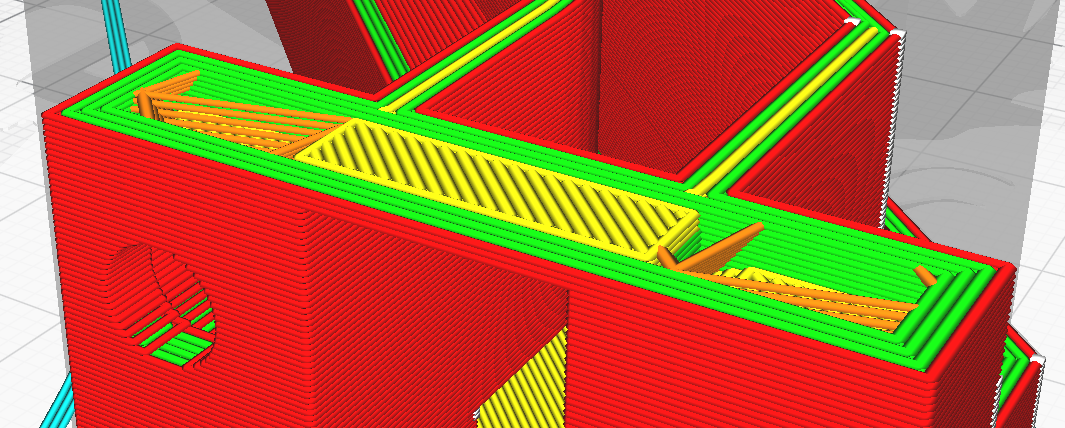
Figure 14: Bridging of Material
Now with the appropriate printing setup, the components are able to be produced in a quality manner. Switching to a more capable printer allowed for a more aggressive design and printing technique to be applied to the component, resulting in a normally unobtainable component using extrusion 3D printing without support material. Figures 15 through 17 below illustrate the comparison of the Lulbot Taz 6 print versus the Ender 3 V2 printing capabilities.
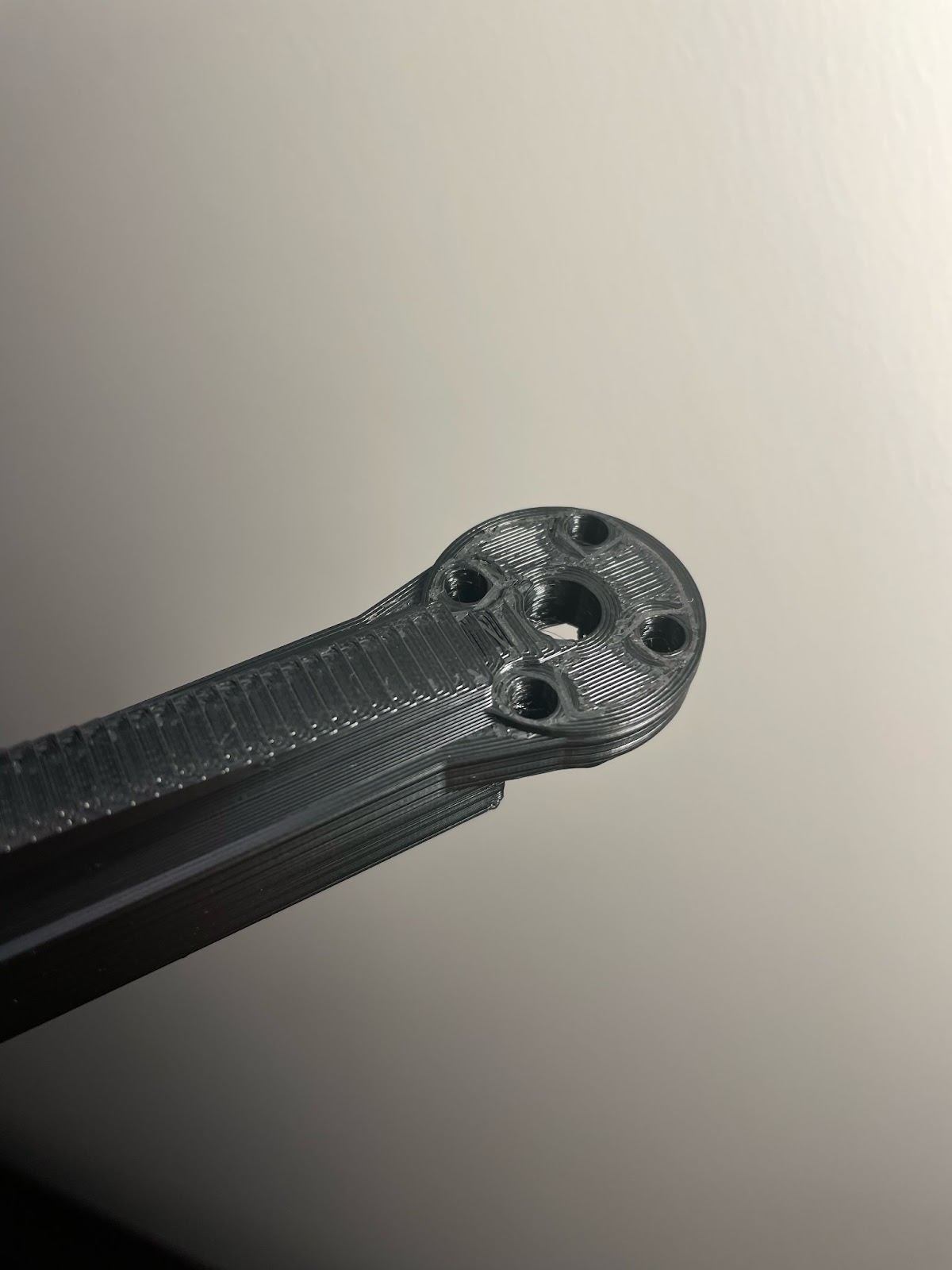
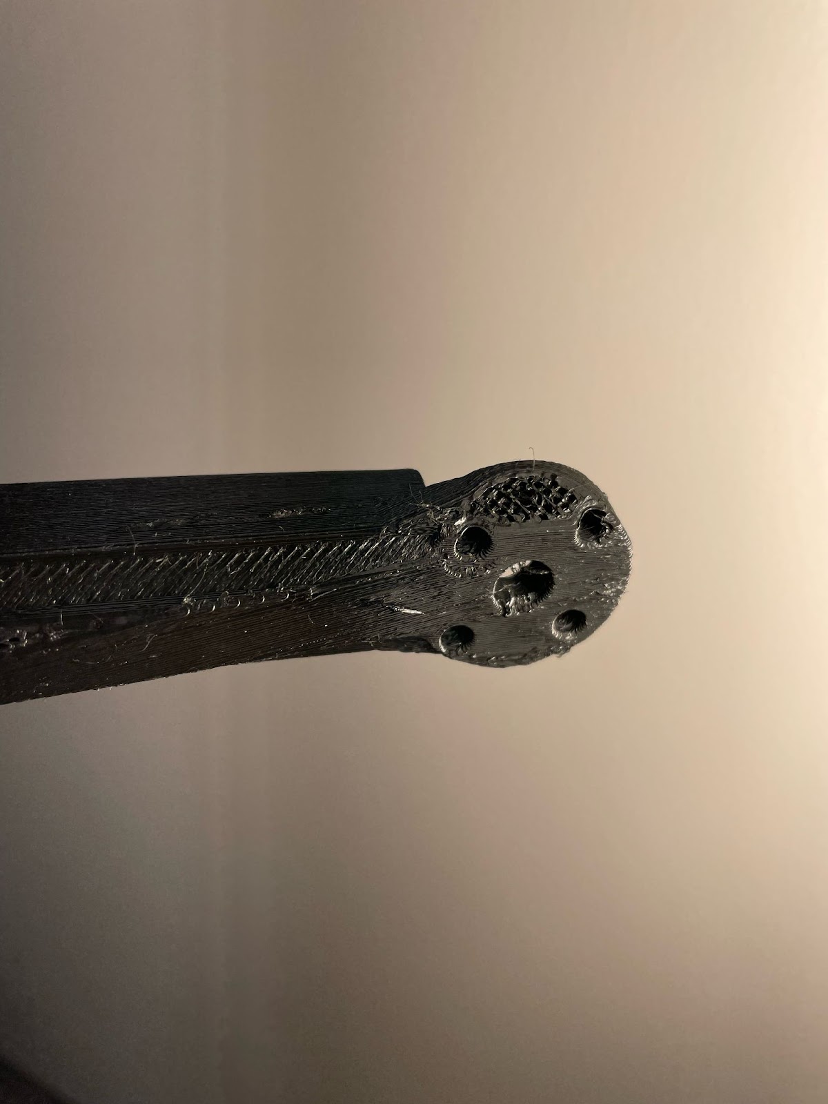
Figure 15: Ender 3 V2 Arm Figure 16: Lulzbot Taz 6 Arm
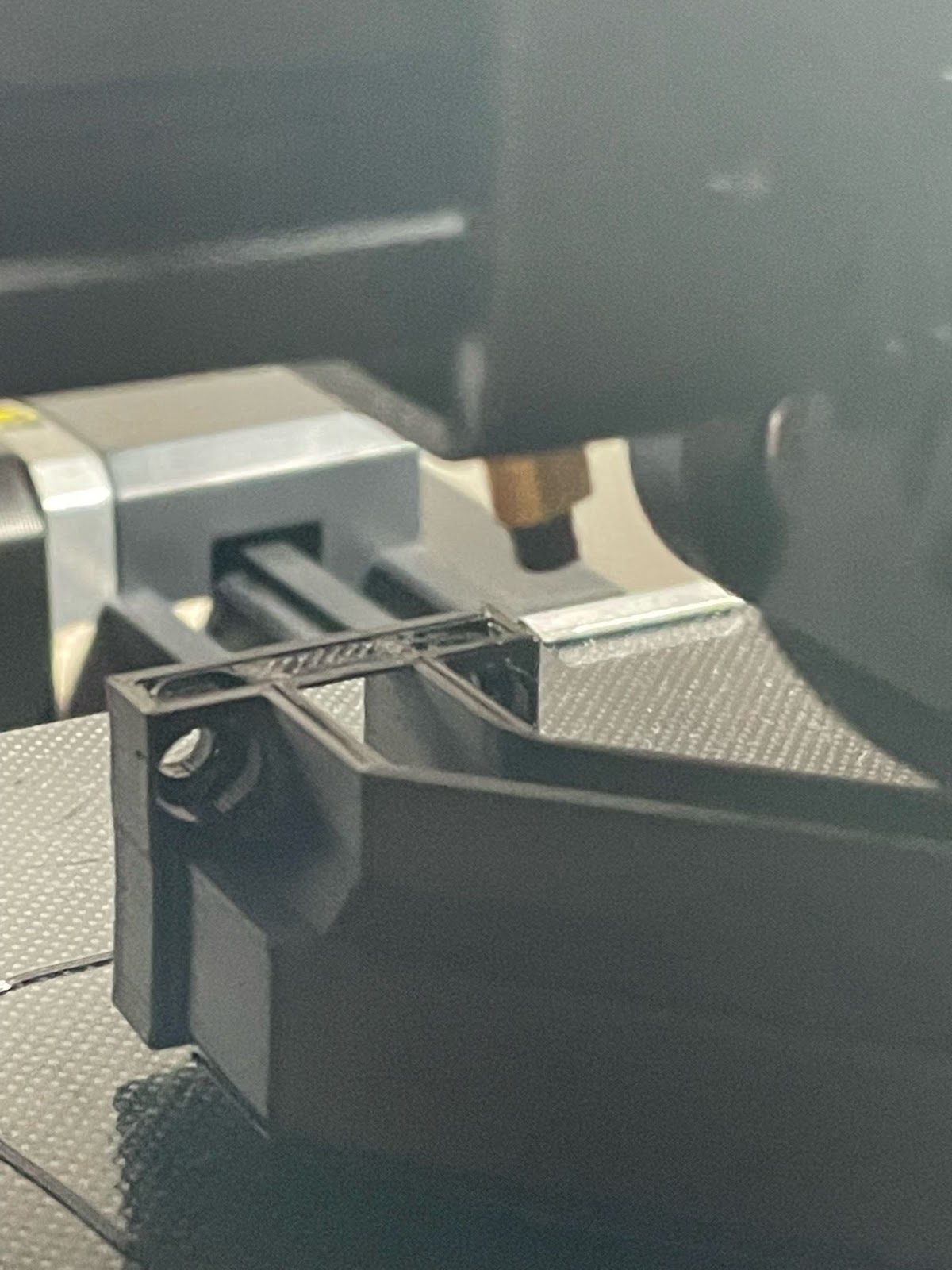
Figure 17: Ender 3 V2 bridging Capabilities
Overall, each of the new arms printed weighs in at 33 grams, 10 grams or 25% lighter than the previous design. This allows for an overall 3D printed mass reduction of 140 grams, or about 34% less than the previous total of 3D printed materials. While the goal of sub-250g was not attainable with the current drone specs and hardware, the work conducted here illustrates the potential to maximize the tools given to produce an aesthetic yet functional component that meets all the goals desired in the project.
IX. Electrical System Modifications and Sensor Additions
A. Overview
When it comes to the electrical side of the Open Source Open Platform Quadcopter, there were two primary design changes that took place from the original project which will be covered in more detail in later sections. First, the flight controller for the original project was an Arduino Uno R3 running an open source flight controller software called MultiWii. Originally, the Arduino Uno R3 was going to be replaced with the Flip Mega 3.5 flight controller from ReadyToFlyQuads.com and programmed using MultiWii as well. However, due to supply chain issues, the Flip Mega 3.5 was never received and a MATEKSYS F405-miniTE was ordered to replace it. This flight controller has a 32-bit processor and thus can use either BetaFlight, CleanFlight, Ardupilot, or iNAV for software. More detail is given in the “Flight Controllers, GPS, and Power Terminal” section below. Second, electrical hardware was added to allow for data collection sensors such as temperature/humidity sensors, air quality sensors, and LiDAR to be added to the quadcopter. More detail about this design change is given in the “Sensor Additions” section below.
B. Flight Controllers, GPS, and Power Terminal
1) Flip Mega 3.5 and MATEKSYS F405-miniTE
The original project used an Arduino Uno R3 as its flight controller and MultiWii as its software. Before making changes to the system, different open source software and flight controllers were researched and considered to fit the new project’s goals. INAV, BetaFlight, CleanFlight, Ardupilot and the original MultiWii were all considered, but ultimately MultiWii was chosen to be used for numerous reasons: 1) To minimize changes to the original design, 2) Keep costs low by using 8 bit microcontrollers instead of 32 bit microcontrollers, 3) Modifying the code and GUI is more accessible. Different flight controllers were also researched and considered, before settling on the Flip Mega 3.5 from readytoflyquads.com. The flight controller is shown in Figure 18 below. This flight controller includes all of the typical IMU sensors on the board and also comes with a GPS module. Both the flight controller and the GPS module are built on a 30.5×30.5mm platform that stack vertically between standoffs. This allows for more flexibility in the scale of the frame for mini drones and larger drones alike.

Figure 18: Flip Mega 3.5 Flight Controller
The Flip Mega 3.5 was the plan originally, but since the new flight controller was never received, the electrical team had to act quickly to replace the flight controller. With the introduction of many 32-bit flight controller software, it’s difficult to find 8-bit based flight controllers with built in IMU’s and other convenient features. ReadyToFlyQuads.com was the only retailer that could be found and since they had proven unreliable, a 32-bit flight controller with the same physical footprint and similar features was chosen. This is what led to the purchase of the MATEKSYS F405-miniTE. The F405-miniTE is built on a 20x20mm platform but comes with a 30.5×30.5mm adapter. This actually came in handy when the time came to mount other boards such as the OpenLog module and RunCam DVR. The new flight controller was flashed with INAV and the INAV configurator was used to program the flight controller. A detailed description on how to program the flight controller, along with images are given in Appendices D & G. A picture of the new flight controller and its features is shown in Figure 19.
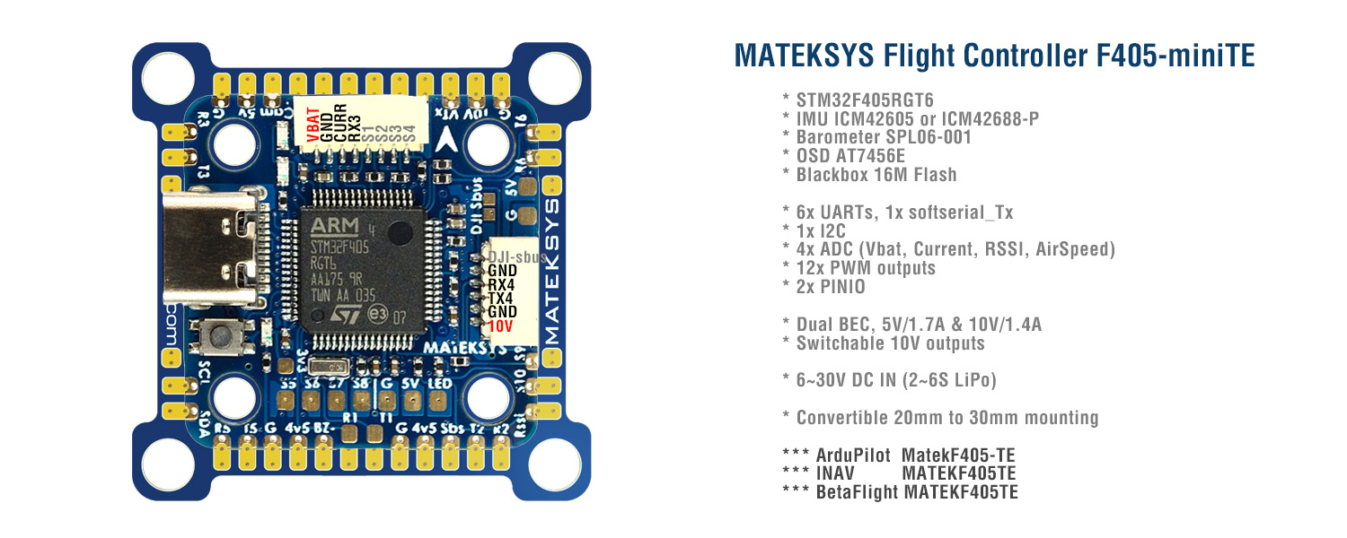
Figure 19: MATEKSYS F405-miniTE Flight Controller
2) MATEKSYS M8Q-5883 and Power Distribution
Along with the replacement of the flight controller, came the addition of a M8Q-5883 GPS/magnetometer module and a power distribution terminal. The GPS communicates with the flight controller using one of the UARTs and the magnetometer compass communicates using the I2C pads. This module was added to allow for mission tracking and to allow for return-to-home (RTH) and other failsafe features to be implemented. The GPS was installed and the programming was updated, but unfortunately GPS and RTH functionality couldn’t be tested due to time and weather constraints. The power distribution terminal was added to split the power from the battery to power the flight controller, each of the four ESCs and the Arduino Nano, which will be discussed in the next section. Images of the GPS and power distribution terminal are shown in Figures 20 and 21 below.

Figure 20: MATEKSYS M8Q-5883

Figure 21: Power Distribution Terminal
C. Sensor Additions
1) Arduino Nano
The original plan for adding data collection sensors was to use the Flip Mega 3.5’s I2C pins and connect various sensors to the flight controller using a custom I2C breakout I/O board. The MultiWii sketch would then be modified to add support for those sensors and to display readings on the MultiWii GUI. However, with the replacement of the Flip Mega 3.5 with the MATEKSYS F405-miniTE, it was realized that using one of the 32-bit open source flight controllers software to handle 3rd party sensors would be either extremely difficult or impossible for a single person to achieve within the time constraints. Instead, it was decided to use an Arduino Nano to handle sensor data instead of the flight controller. To achieve this, a sketch was written to initialize connections to and poll data from a SHT30 temperature/humidity sensor, a SGP30 air quality sensor, and a DFRobots LIDAR07 LiDAR sensor every second. The sketch is designed to allow users to comment out sensors that they aren’t using and comment in sensors that they are using. This design also allows for future project contributors to add support for different models of sensors without having to completely redesign the sketch. Additionally, there is commentable “#define” statements for seeing data on the serial monitor as well as recording data to the black box. This will be detailed in the “OpenLog” section. The Nano is mounted and connected with sensors/power using a screw terminal shield. Images of the sensors that support was added for are in Figures 22-24 below.
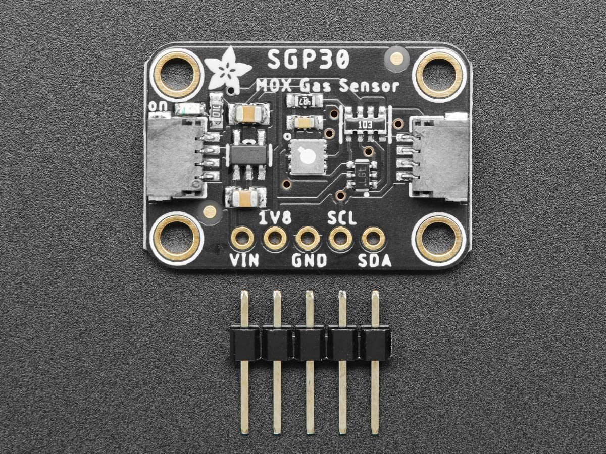
Figure 22: SGP30 Sensor
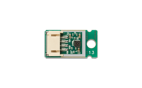
Figure 23: SHT30 Sensor
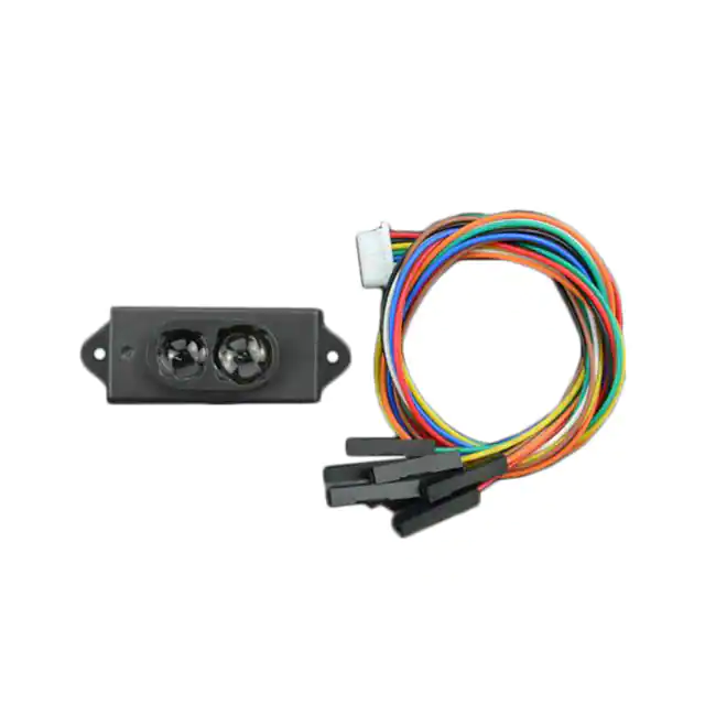
Figure 24: LIDAR07 Sensor
2) I/O Board
Additionally, a custom I/O PCB was designed and built on the same 30.5×30.5mm platform as the flight controller to allow for easy addition and removal of various peripheral components. Components included but aren’t limited to: humidity sensors, air quality sensors, and LiDAR. The first iteration of the board was built around an I2C multiplexer with inputs/outputs as JST connectors for plug-and-play performance. However, it was realized during testing that the I2C multiplexer outputs/inputs are GPIO which isn’t compatible with the sensors chosen. The PCB was redesigned without the multiplexer (since I2C can be daisy chained), but time constraints prevented the second iteration from being printed and soldered. All sensors were instead connected and tested by wiring them in parallel with the Arduino Nano screw terminal shield. The second iteration maintains similar input and outputs though. It has one 6-pin JST input which connects to the Arduino Nano’s 5V pin, 3.3V pin, GND pin, SCL pin, SDA pin, and one of the digital pins. The digital pin connection is meant to handle interrupts for the LiDAR. Additionally, there are three 4-pin JST outputs, one of which is powered by 3.3V and two which are powered by 5V. There are two 5-pin JST outputs, one of each for 5V and 3.3V. Finally, there is one 8-pin JST output which is specifically for the LiDAR which is powered with 5V. The reason that some outputs are powered by 3.3V and some by 5V is due to different sensor brands using different input voltages. Most Adafruit I2C devices, such as the SGP30, use 5V. However, most Sparkfun I2C devices, such as the OpenLog black box use 3.3V. Finally, although there are only three 4-pin JST outputs, the two 5-pin outputs can be used by 4-pin input devices. The first iteration’s PCB and its KiCAD preview are shown in Figures 25 & 26 below along with the schematic and board layout in Figures 27 & 28. Below them in Figures 29-31 are the second iteration’s PCB preview, board layout and schematic.
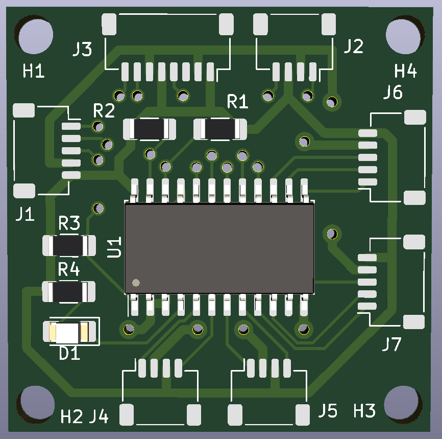
Figure 25: I/O PCB KiCAD
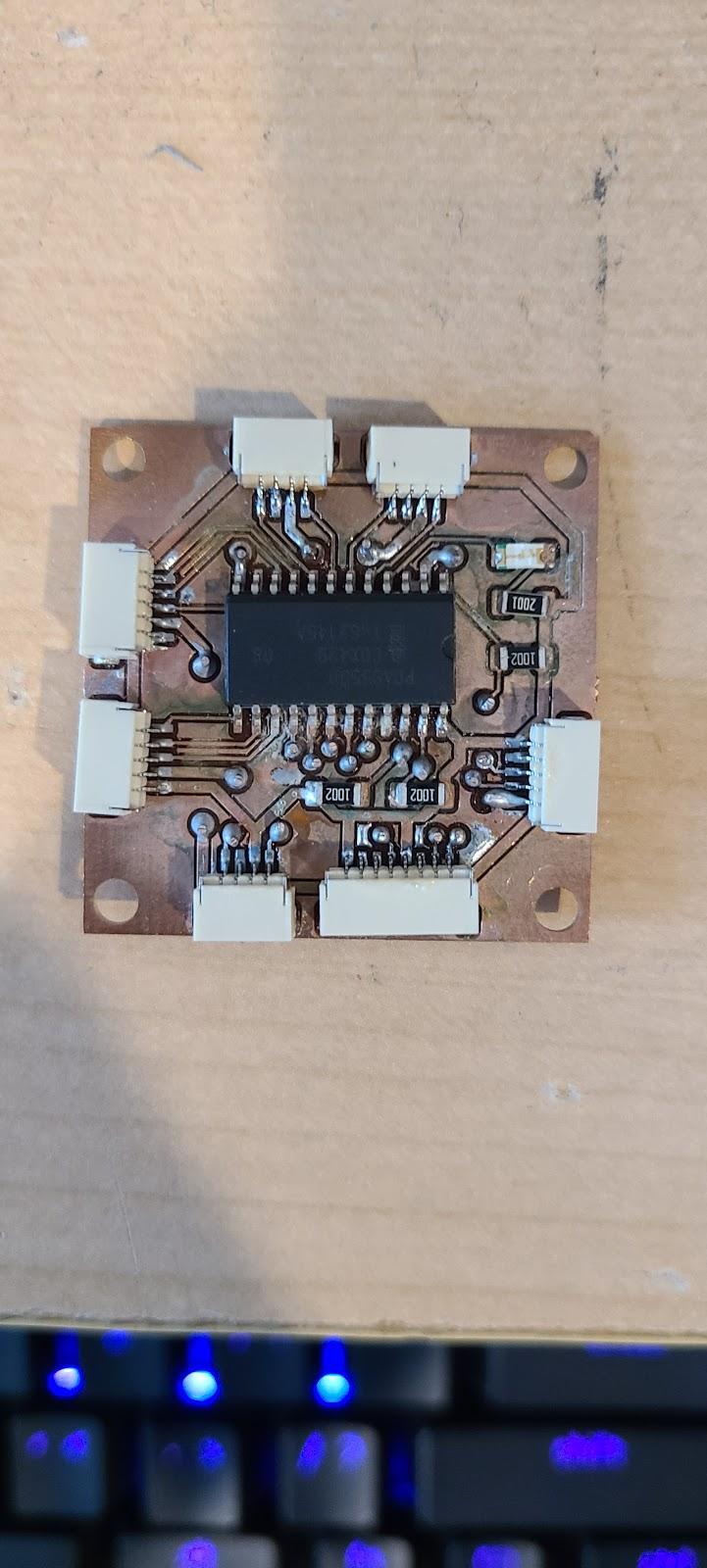
Figure 26: I/O PCB
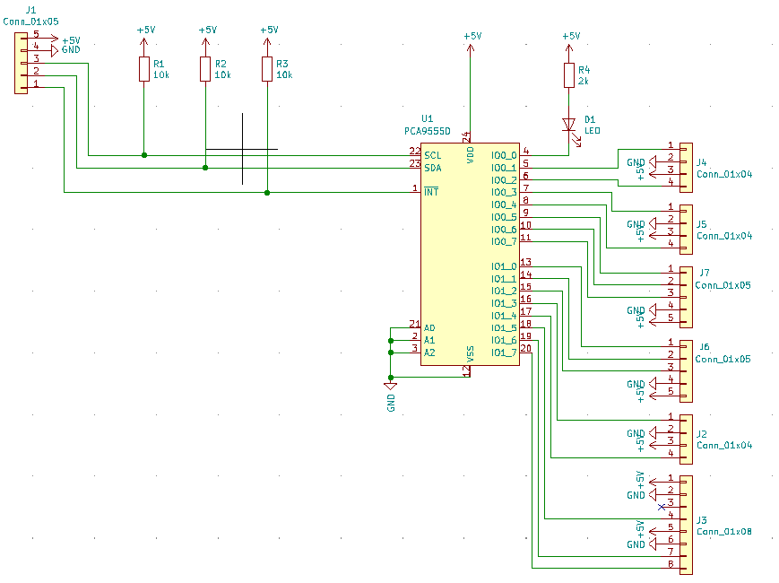
Figure 27: I/O PCB Schematic
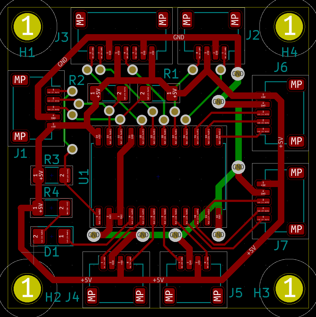
Figure 28: I/O PCB Board Layout
The new electrical system will allow users to add the peripheral components necessary for their specific application, be it cinematography (the original project), plotting atmospheric/pollution data at different GPS coordinates and altitudes, scanning the ground for desired data using LiDAR, or many other potential applications.

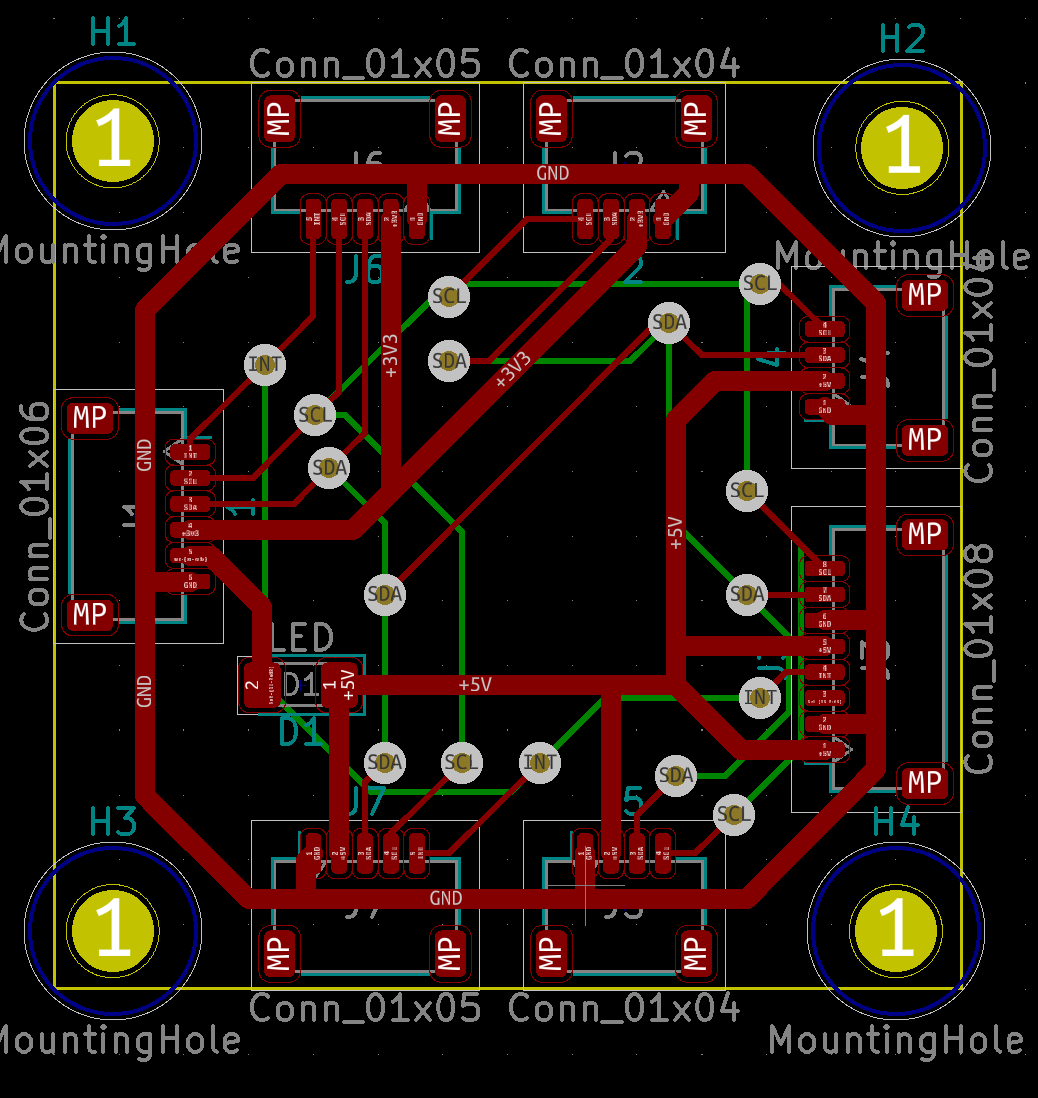
Figure 29: I/O Board V2 Preview Figure 30: I/O Board V2 Layout
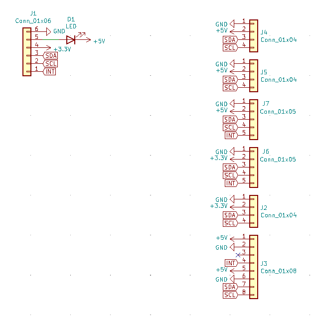
Figure 31: I/O Board V2 Schematic
3) OpenLog
In addition to the sensor support being added to the Arduino Nano sketch, support for SparkFun’s Qwiic OpenLog black box module was also added. The Qwiic OpenLog module has a 4-pin JST connector input for I2C, power, and ground, which makes it perfect for use with the I/O board. The OpenLog board also has a microSD card slot for logging data to any microSD card formatted in FAT16 or FAT32. The Arduino sketch mentioned in the “Arduino Nano” section also contains a commentable “#define OpenLog_I2C” statement for the OpenLog module. When users uncomment this statement, the OpenLog module will take the sensor data from all connected and defined sensors and log them to a “.csv” file every second. Data columns for sensors that aren’t connected/defined will be filled with “NaN” for easy identification. The original plan was to also add support for acquiring telemetry data from the flight controller over one of the spare UARTs and the Nano’s serial pins via the MAVLINK protocol. However, after extensive troubleshooting, this functionality couldn’t be achieved. Columns were added to the OpenLog code for use with this data along with functions and “#define” statements to support MAVLINK functionality. If future contributors can get this functionality added, it would greatly benefit the project. Also a “#define serial_monitor” statement was added so some initialization text for the sensors and OpenLog will be displayed to the serial monitor followed by the data that is being uploaded to the OpenLog “.csv” file. A picture of what the OpenLog module looks like is in Figure 32 below.
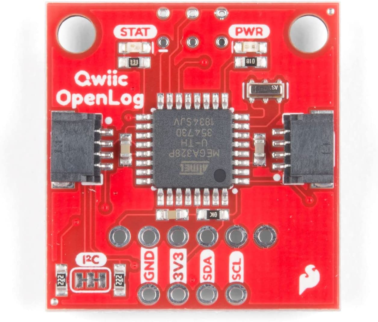
Figure 32: Qwiic OpenLog Module
X. Conclusions and Future Work
Overall, the mechanical goals set by the Open Source Open Platform Quadcopter team were able to be achieved through the use of Altair’s Inspire and various manufacturing techniques. The team was able to achieve a design that allowed for the retention of prior integrity standards, but also introduced new features such as fully enclosed wiring within the components and a lightweight and modular design. This was achievable by utilizing the optimization feature in Inspire where AI is able to reduce a generic component with set design spaces and output the necessary areas of the component that must be retained for such loadcases being applied.
One area that was not able to be fully investigated was a comprehensive Tensile and 3-Point Bending test, so further research on such material testing can be done. More importantly the 3-Point bend test following ASTM D790 standard will allow for the future mechanical team to regress both data sets (Tensile and Compressive tests) to understand if there is an optimal point of infill density that can be utilized within components. The testing materials and designs have already been completed, so testing with the Mechanical Engineering department can be set up to finish such. Along with these tests, a tensile test of the new arm design compared to the original arm design can also be conducted to validate FEA calculations. Again, the files for such will be accessible to the future Open Source Open Platform Quadcopter team so testing can be arranged at the same time as the Tensile and Compressive tests.
When it comes to the overall mechanical standing of the new drone, the chassis design is complete and printed. However, mounting holes for heat set inserts didn’t exist for the specific electrical hardware added in the fall semester. Holes were drilled by the electrical team to accommodate mounting of the Arduino Nano, flight controller, OpenLog module, RunCam DVR, RunCam, and LiDAR. Additionally, an open source design file for a RunCam mount was printed and mounted to the cover for attaching the RunCam. Also, the channels in the arms are slightly too small for inserting the ESCs which led them to be mounted adhoc in the center console. Future, mechanical team members should use this report and work with electrical team members to make minor modifications to the CAD design files to print holes for mounting in the center console and top cover. They should also slightly widen the arms to allow for insertion of the ESCs.
Regarding the electrical goals of this project, nearly everything has been achieved, at least in theory. Some goals are yet to be physically implemented, but the quadcopter has the electrical hardware and software to fly in all axes, and be controlled by a teleoperator on the ground. Support for data collection sensors and data logging were also added for three different sensors. Unfortunately, no good way for transmitting data without producing interference between the transmitter and receiver were found, therefore data can only be accessed post flight. GPS was added for RTH functionality and coordinate tracking. The I/O board final design was achieved, but wasn’t printed, soldered and tested.
For future electrical team members, addition of support for acquisition of telemetry data from the flight controller using MAVLINK or another telemetry protocol should be added to the Arduino sketch. Testing of the GPS and addition of RTH functionality should also be done when the weather allows it. Printing, soldering and testing of the I/O board V2 should be done before adding it to the flight controller stack. Collaboration with the mechanical team should be done to add mounting for existing and future sensors. Finally, once everything is tested, support for additional sensors can be added to the Arduino sketch. This along with the addition of MAVLINK may require upgrading from an Arduino Nano to a more powerful microcontroller with more memory.
Pictures of the quadcopter in its current state are shown in Figure 33-38 below.
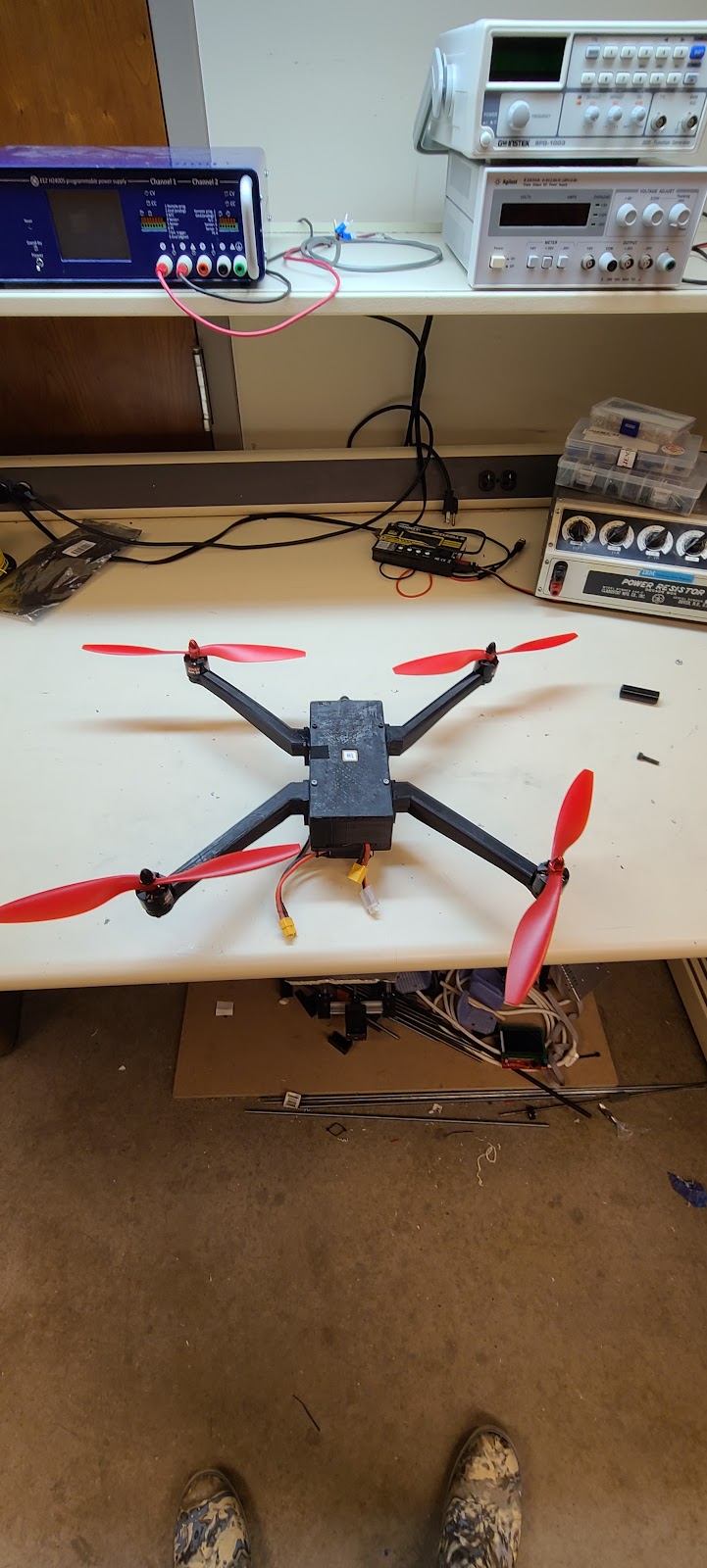
Figure 33: Quadcopter fully assembled with top cover on.

Figure 34: Quadcopter fully assembled with top cover off.

Figure 35: Close up of center console.

Figure 36: Close up of RunCam mount.
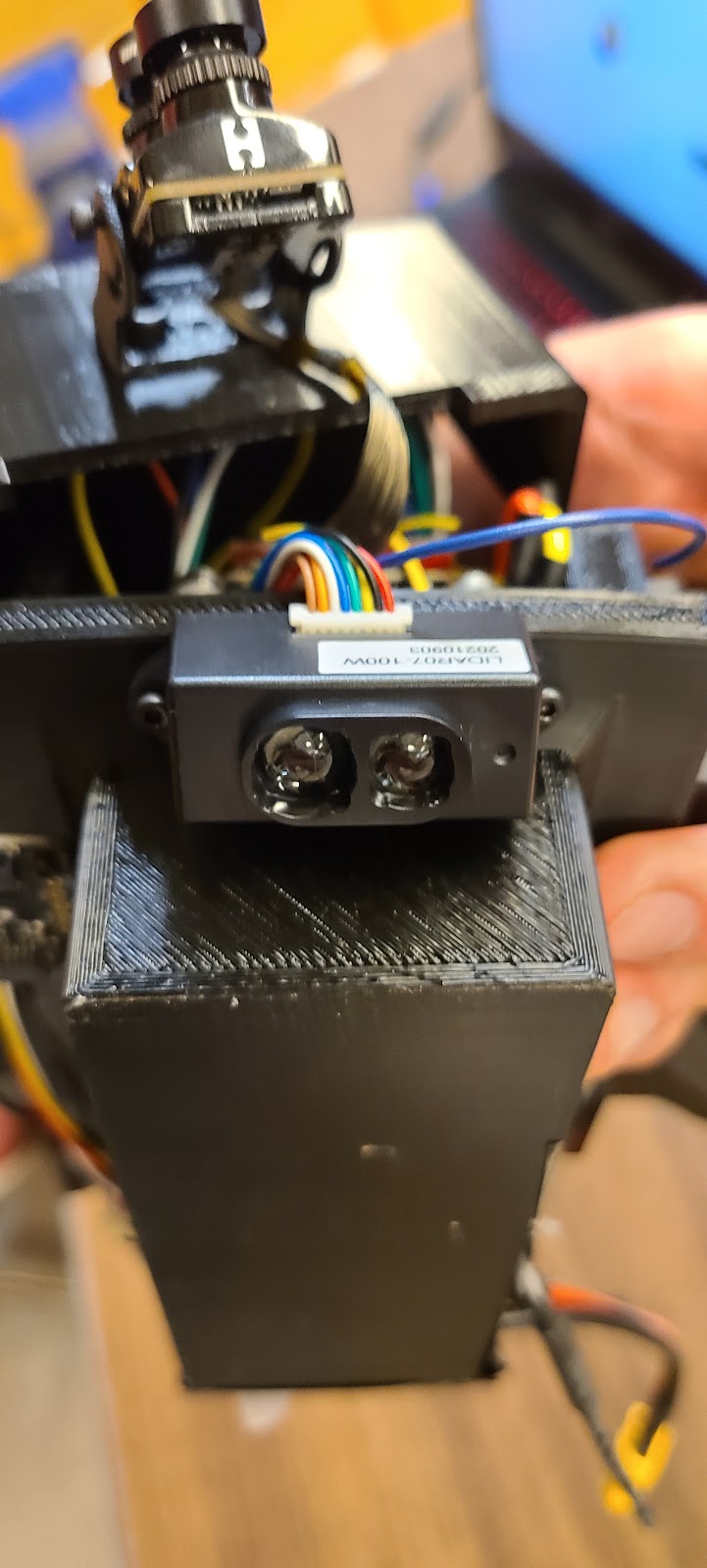
Figure 37: Close up of mounted LIDAR.
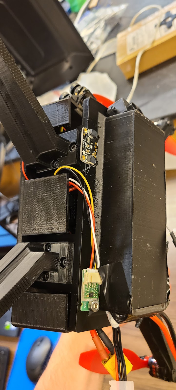
Figure 38: Close up of mounted air quality and temperature/humidity sensors.
XI. References and Research Findings
1. Bhandari, A., Ahmad, F., Kumar, P., & Patil, P. P. (2019). (tech.). Design and Vibration Characteristics Analysis of Quadcopter Body Frame. International Journal of Applied Engineering Research. Retrieved March 2021, from https://www.ripublication.com/ijaerspl2019/ijaerv14n9spl_13.pdf.
2. Javir, A. V., Pawar, K., Dhudum, S., Patale, N., & Patil, S. (2015). (tech.). Design, Analysis and Fabrication of Quadcopter. Journal of Advance Research in Mechanical and Civil Engineerin. Retrieved March 2021, from https://www.google.com/url?sa=t&rct=j&q=&esrc=s&source=web&cd=&ved=2ahUKEwjexdH8xM30AhXLG80KHVsXD64QFnoECAQQAQ&url=https%3A%2F%2Fnnpub.org%2Findex.php%2FMCE%2Farticle%2Fdownload%2F342%2F304&usg=AOvVaw06khR3MMLkmDOntZsxSDwj.
3. Kuantama, E., Craciun, D., & Tarca, R. (2016). (tech.). QUADCOPTER BODY FRAME MODEL AND ANALYSIS. University of Oradea. Retrieved March 2021, from http://imt.uoradea.ro/auo.fmte/files-2016-v1/Endrowednes%20Kuantama%20-%20Final%20Quadcopter%20Bodyframe%20Model%20and%20Analysis.pdf.
4. Parandha, S. M., & Li, Z. (2018). (tech.). Design and Analysis of 3D Printed Quadrotor Frame. International Advanced Research Journal in Science, Engineering and Technology. Retrieved March 2021, from https://iarjset.com/upload/2018/april-18/IARJSET%2011.pdf.
5. Santiago, J. M., & Kasley, K. L. (2017). (tech.). Design & Development of a 3D-Printed Quadcopter Using A System Engineering Approach in an Electrical Engineering Masters Capstone Course (pp. 1–22). American Society for Engineering Education.
6. Simplify3D Software. (2019, May 30). Properties table. All-In-One 3D Printing Software. Retrieved March 2021, from https://www.simplify3d.com/support/materials-guide/properties-table/.
7. Yemle, S., Durgude, Y., Kondhalkar, G., & Pol, K. (2019). (tech.). Design & Analysis of Multi-Frame for Octo & Quad Copter Drones. International Research Journal of Engineering and Technology (IRJET). Retrieved March 2021, from https://www.irjet.net/archives/V6/i6/IRJET-V6I6596.pdf.
8. Recreational Flyers & Modeler Community-Based Organizations. (2021, September 2). Retrieved December 10, 2021, from https://www.faa.gov/uas/recreational_fliers/.
9. Dielectric Manufacturing. (2021, November 19). Material properties of thermoplastic PETG. Dielectric Manufacturing. Retrieved December 10, 2021, from https://dielectricmfg.com/knowledge-base/petg/.
10. Journal of Advanced Materials Science and Engineering (2021, August 1). Experimental Analysis on 3d Printed Onyx Specimens with Honeycomb Infill Structure. Retrieved May 15, 2021.
11. Revista de Metalurgia 57 (3) (2021, July 1) Mechanical characterization of polylactic acid polymer 3D printed materials: the effects of infill geometry. Retrieved May 15, 2021.
XII. Appendix
Appendix A: Assembly BOM
| Minimum Electrical Parts for Flight | ||||||
| Part Name | Manufacturer | Seller | Quantity | Part Number | Cost (Each) | Cost (Total) |
| Flight Controller F405-miniTE | MATEKSYS | GetFPV | 1 | 17698 | $59.99 | $59.99 |
| ESC | Turnigy MultiStar | HobbyKing | 4 | 9351000087-0 | $10.97 | $43.88 |
| Motors (CW) | Emax | UnmannedTechShop | 2 | MT2213-935KV-CW | $15.80 | $31.60 |
| Motors (CCW) | Emax | UnmannedTechShop | 2 | MT2213-935KV-CCW | $15.80 | $31.60 |
| Propellers (8 pack) | RAYCorp | Amazon | 1 | B01CJMJ886 | $12.97 | $12.97 |
| Battery | Goldbat | Amazon | 1 | B07LGZ3TVM | $25.99 | $25.99 |
| Receiver and Transceiver Combo | Flysky | Amazon | 1 | B0744DPPL8 | $49.99 | $49.99 |
| Power Distribution Block | Jienk | Amazon | 1 | B0B55RGG6J | $13.99 | $13.99 |
| Total | $270.01 |
| Add-On Sensors | ||||||
| Part Name | Manufacturer | Seller | Quantity | Part Number | Cost (Each) | Cost (Total) |
| Arduino Nano | Arduino | Amazon | 1 | B0097AU5OU | $26.91 | $26.91 |
| GPS M8Q-5883 | MATEKSYS | Amazon | 1 | B081X1VX2M | $42.99 | $42.99 |
| LiDAR Sensor | DFRobot | Digikey | 1 | 1738-SEN0413-ND | $19.90 | $19.90 |
| Temp/Humidity Sensor | Sensirion AG | Digikey | 1 | 1649-1111-ND | $13.39 | $13.39 |
| SGP30 MOX Sensor | Adafruit | Amazon | 1 | B07L5YN11R | $21.98 | $21.98 |
| Camera w/ DVR | RunCam | RaceDayQuads | 1 | $89.99 | $89.99 | |
| OpenLog | SparkFun | Amazon | 1 | B07P7RX4W7 | $18.50 | $18.50 |
| MicroSD Card w/ SD Adapter | SanDisk | Amazon | 2 | B0B7NXBM6P | $11.92 | $23.84 |
| Arduino Nano Screw Terminal | Amazon | 1 | B073JGV87F | $8.79 | $8.79 | |
| Total | $266.29 |
| 3D Printed Parts | |||||
| Part Name | Part File | Quantity | Weight (g) | Cost (Each) | Cost (Total) |
| Center Chassis | CenterConsole.stl | 1 | 250.00 | $5.00 | $5.00 |
| CW Arm | FinalArmFrontLeft.stl | 2 | 40.00 | $0.80 | $1.60 |
| CCW Arm | FinalArmFrontRight.stl | 2 | 40.00 | $0.80 | $1.60 |
| Top Cover | TopCover.stl | 1 | 90.00 | $1.80 | $1.80 |
| Runcam Mount | RunCam_Mount_V1.stl | 1 | 10.00 | $0.20 | $0.20 |
| Cost of Petg 2.85mm ($/g) | 0.02 | Total | $10.20 |
| Hardware | |||||
| Part Name | Manufacturer | Quantity | Part Number | Cost (Each) | Cost (Total) |
| M2 Heat Insert | McMaster-Carr | 2 | 94459A120 | $0.24 | $0.48 |
| M2 Nut | McMaster-Carr | 2 | 90592A075 | $0.04 | $0.08 |
| M2 Spacer | McMaster-Carr | 4 | 93657A208 | $1.43 | $5.72 |
| M2 x 4 | McMaster-Carr | 4 | 91290A011 | $0.17 | $0.66 |
| M2 x 12 | McMaster-Carr | 4 | 91290A019 | $0.16 | $0.63 |
| M2 x 20 | McMaster-Carr | 2 | 91290A049 | $0.15 | $0.30 |
| M3 Heat Insert | McMaster-Carr | 22 | 94459A130 | $0.25 | $5.50 |
| M3 Standoff | McMaster-Carr | 6 | 93655A097 | $4.26 | $25.56 |
| M3 x 8 | McMaster-Carr | 16 | 91290A049 | $0.09 | $1.48 |
| M3 x 10 | McMaster-Carr | 4 | 91290A115 | $0.10 | $0.38 |
| M3 x 12 | McMaster-Carr | 18 | 91290A117 | $0.11 | $1.95 |
| M4 Nut | McMaster-Carr | 1 | 90592A090 | $0.03 | $0.03 |
| M4 x 12 | McMaster-Carr | 1 | 91290A148 | $0.12 | $0.12 |
| Total | $38.94 |
| I/O Board | |||||
| Part Name | Seller | Quantity | Part Number | Cost (Each) | Cost (Total) |
| Green LED | Digikey | 1 | 732-4990-1-ND | $0.22 | $0.22 |
| 8 Position JST Socket (5 pcs) | HobbyKing | 1 | 258-000187-0 | $0.72 | $0.72 |
| 5 Position JST Socket (5 pcs) | HobbyKing | 1 | 258-000185-0 | $0.47 | $0.47 |
| 4 Postition JST Socket (5 pcs) | HobbyKing | 1 | 258-000184-0 | $1.44 | $1.44 |
| 6 Position JST Socket (5 pcs) | HobbyKing | 1 | 258-000186-0 | $0.54 | $0.54 |
| 8 Position JST Cable | Digikey | 1 | 455-3016-ND | $2.12 | $2.12 |
| 5 Position JST Cable | Digikey | 2 | 455-3710-ND | $1.57 | $3.14 |
| 4 Postition JST Cable | Digikey | 3 | 455-3002-ND | $1.42 | $4.26 |
| 6 Position JST Cable | Digikey | 1 | 455-3003-ND | $1.72 | $1.72 |
| Total | $14.63 |
| Total Cost | |
| Part Category | Cost (Total) |
| Minimum Electrical System | $270.01 |
| 3D Printed Parts | $10.20 |
| Hardware | $38.94 |
| Add-On Sensors | $266.29 |
| I/O Board | $14.63 |
| Minimum Cost Total | $319.15 |
| Cost Total w/ All Add-ons | $600.07 |
Appendix B: Electrical/Mechanical Hardware Assembly Procedure
This assembly procedure describes the required steps to assemble the mechanical/electrical portion of the quadcopter.
- The table below lists all the required hardware and tools necessary to completely assemble the frame and components of the quadcopter.
| Hardware and Tooling | ||
| Component | Description | Quantity |
| Heat Set Insert | M2 Heat Insert | 2 |
| Fastener | M2 Nut | 2 |
| Spacer | M2 Spacer | 4 |
| Fastener | M2 x 4 | 4 |
| Fastener | M2 x 12 | 4 |
| Fastener | M2 x 20 | 2 |
| Heat Set Insert | M3 Heat Insert | 22 |
| Standoff | M3 Standoff | 6 |
| Fastener | M3 x 8 | 16 |
| Fastener | M3 x 10 | 4 |
| Fastener | M3 x 12 | 18 |
| Fastener | M4 Nut | 1 |
| Fastener | M4 x 12 | 1 |
| Tooling | Description | Quantity |
| Allen Key | M2 | 1 |
| Allen Key | M3 | 1 |
| Soldering Iron | Typical Soldering Iron | 1 |
| Needle Nose Pliers | Small | 1 |
- Print all printable components using 2.85mm PETG with a bed temperature of 75°C and an extruder temperature of 240°C. Use a brim and no support for all parts. Use 100% infill for the arms and RunCam mount and 50% infill on the center console and top cover.
- Utilize the soldering iron to insert the M3 heat inserts into the 16 countersunk holes in the center chassis. Place the soldering iron inside the heat set insert and apply a small amount of pressure downwards making sure that the heat set insert gets installed straight. You can also utilize a bolt threaded onto the heat insert to help guide it into place for the tough to reach areas.
- Plug in the motor wires to the ESC and utilizing a guide wire fish the wiring through the arm until it is protruding from the other end.
- Bolt on the motors to the end of the arm utilizing the 4 M3 x 8 bolts. Do not over tighten as the bolts can easily pull through the material.
- After the wiring is fished through, guide the wires through the access hole on the center chassis and bolt on each arm utilizing 3 M3 x 12 bolts in each connection.
- Using the pictures in Section X to drill holes for the heat inserts for the flight controller and Arduino Nano shield standoffs.
- Using the pictures in Section X drill holes for mounting the LIDAR, temperature/humidity sensor, and air quality sensor. The LIDAR and air quality sensor use M2 x 12 screws while the temperature/humidity sensor uses an M4 x 12 screw. The LIDAR and temperature/humidity sensor were bolted through the center console, while the air quality sensor was mounted using M2 heat inserts.
- Use the holes drilled and heat inserts inserted to mount the sensors.
- Using the pictures in Section X as a guide, drill holes in the front of the top cover to mount the RunCam mount using M3 x 10 screws. Then mount the RunCam mount using M3 x 10 screws and nuts.
- Install M3 standoffs for the flight controller and Arduino Nano shield.
- Wire/solder the electrical system together using the wiring diagram in Appendix E as a guide.
- Dremel a hole for the antenna of the GPS to fit through in the top cover and fasten the GPS module to it.
- Using M2 x 20 screws, M2 spacers and M2 nuts mount the OpenLog module and RunCam DVR to the flight controller. Insert microSD cards into the DVR and OpenLog module.
- Using M3 x 12 screws, mount the flight controller stack to its standoffs.
- Using M3 x 12 screws, mount the Arduino Nano shield with the Arduino Nano to their standoffs.
- Fasten the power distribution terminal to the center console.
- Use the Arduino Nano shield to secure the receiver.
- Bolt the top cover to the center console using M3 x 10 screws and feed the sensor/RunCam wires out the gaps at the bottom.
- Mount the RunCam to its mount using M2 x 4 screws.
- Insert the battery into its slot and fasten it.
Appendix C: Programming/Software Procedure
The programming procedure describes the required steps to program the flight controller and Arduino Nano.
- Download INAV configurator 5.1 from the Github link listed in Appendix G.
- Connect the flight controller to your computer using a USB Type C cable.
- Go to the MATEKSYS F405-miniTE link in Appendix G and click on the download Firmwares button and download the INAV 5.1.0 configuration file.
- Launch the INAV configurator and go to the flash firmware tab and upload the configuration file and flash it to the flight controller.
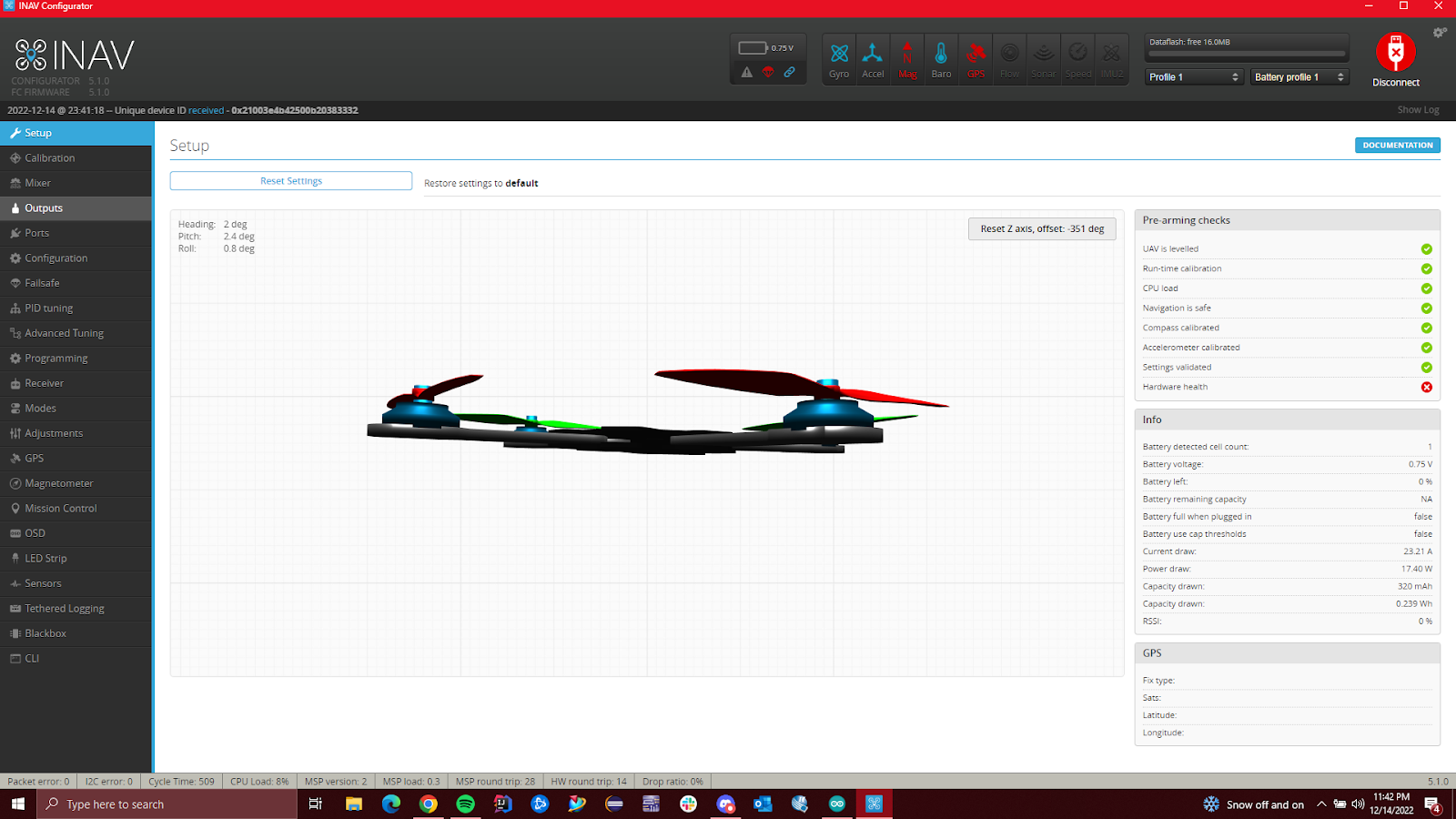
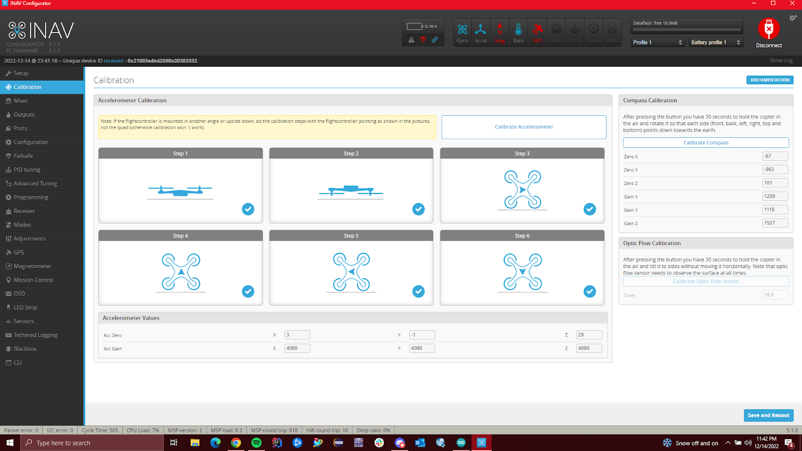
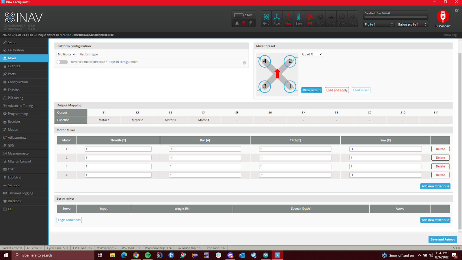
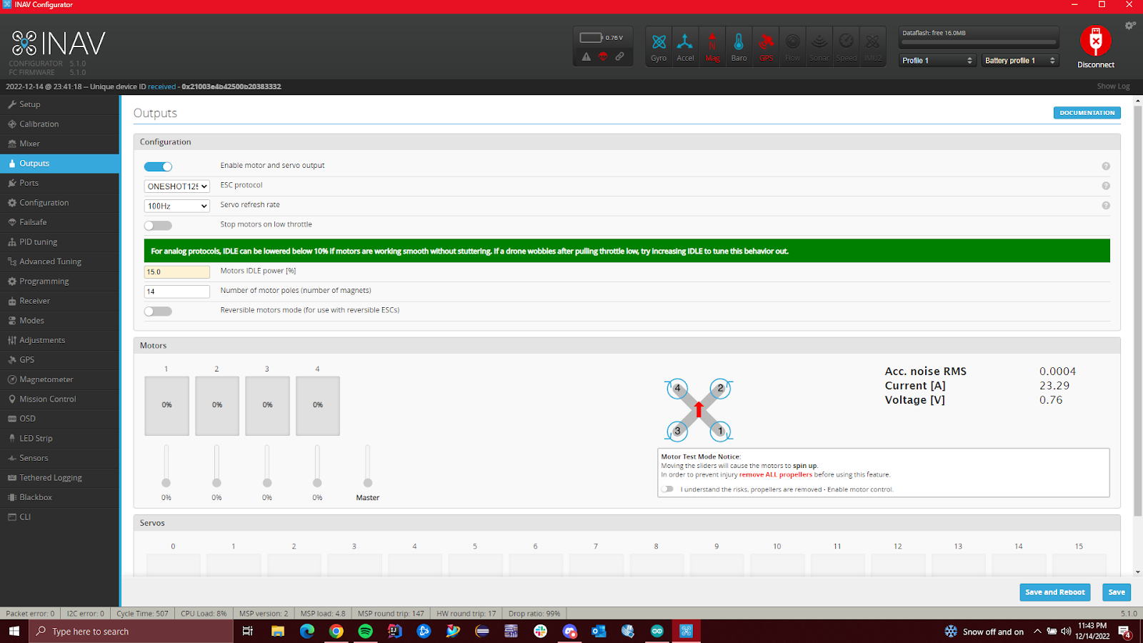
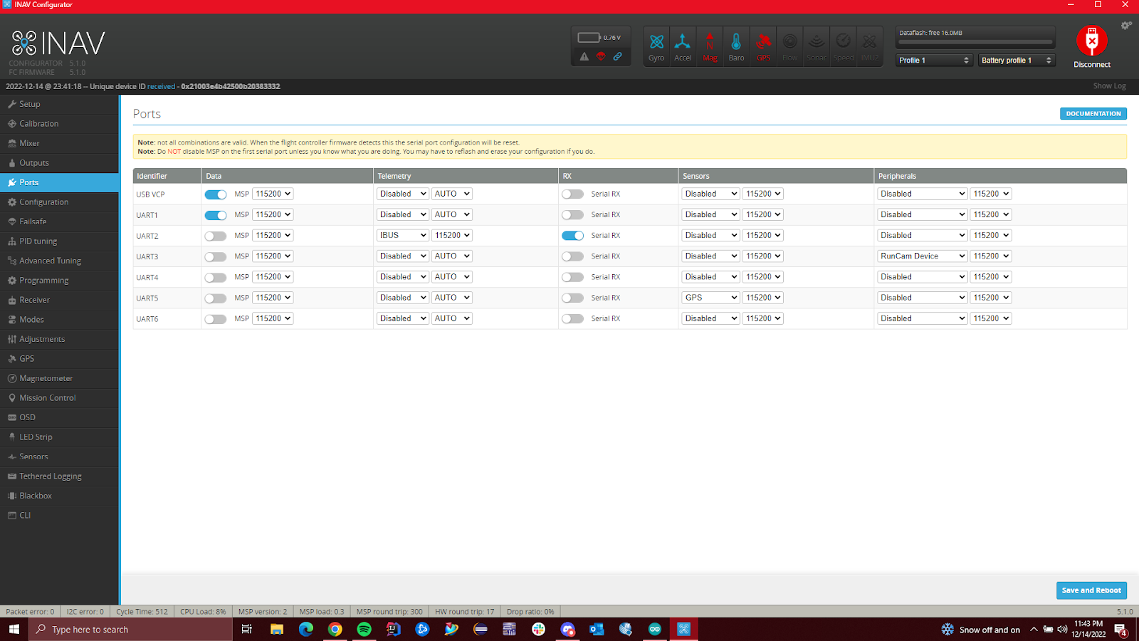
- Connect INAV to the flight controller and set up the tabs according to the images in Appendix F.
- Download the Arduino sketch in the OSF link in Appendix G.
- Download the required libraries from the links in Appendix G.
- Launch the sketch in the Arduino IDE and set up the board and comm channel under tools.
- Uncomment the “#define” statements for the sensors that you’re using.
- If you wish to test and troubleshoot the code and sensors, uncomment the “#define serial_monitor” statement and ensure that the serial monitor outputs data correctly before testing again with the OpenLog and microSD card.
Appendix D: PETG Material Properties
| Material Properties of Thermoplastic PETG – Exceptionally Durable | ||||||
| Property | Metric | units | English | units | ||
| General | ||||||
| Density | 1.26e3 – 1.28e3 | kg/m^3 | 0.0455 – 0.0462 | lb/in^3 | ||
| Mechanical | ||||||
| Yield Strength | 4.79e7 – 5.29e7 | Pa | 6.95 – 7.67 | ksi | ||
| Tensile Strength | 6e7 – 6.6e7 | Pa | 8.7 – 9.57 | ksi | ||
| Elongation | 1.02 – 1.18 | % strain | 102 – 118 | % strain | ||
| Hardness (Vickers) | 1.41e8 – 1.56e8 | Pa | 14.4 – 15.9 | HV | ||
| Impact Strength (un-notched) | 1.9e5 – 2e5 | J/m^2 | 90.4 – 95.2 | ft.lbf/in^2 | ||
| Fracture Toughness | 2.11e6 – 2.54e6 | Pa/m^0.5 | 1.92 – 2.31 | ksi/in^0.5 | ||
| Young’s Modulus | 2.01e9 – 2.11e9 | Pa | 0.292 – 0.306 | 10^6 psi | ||
| Thermal | ||||||
| Max Service Temperature | 51 – 64 | °C | 124 – 147 | °F | ||
| Melting Temperature | 81 – 91 | °C | 178 – 196 | °F | ||
| Insulator or Conductor | Insulator | Insulator | ||||
| Specific Heat Capability | 1.47e3 – 1.53e3 | J/kg °C | 0.352 – 0.366 | BTU/lb. °F | ||
| Thermal Expansion Coefficient | 1.2e-4 – 1.23e-4 | strain/°C | 66.8 – 68.1 | µstrain/°F | ||
| Eco | ||||||
| CO2 Footprint | 3.22 – 3.56 | kg/kg | 3.22 – 3.56 | lb/lb | ||
| Recyclable | Yes | Yes | ||||
| Dielectric Manufacturing, Richfield, Wisconsin USA dielectricmfg.com |
Appendix E: Wiring Diagram

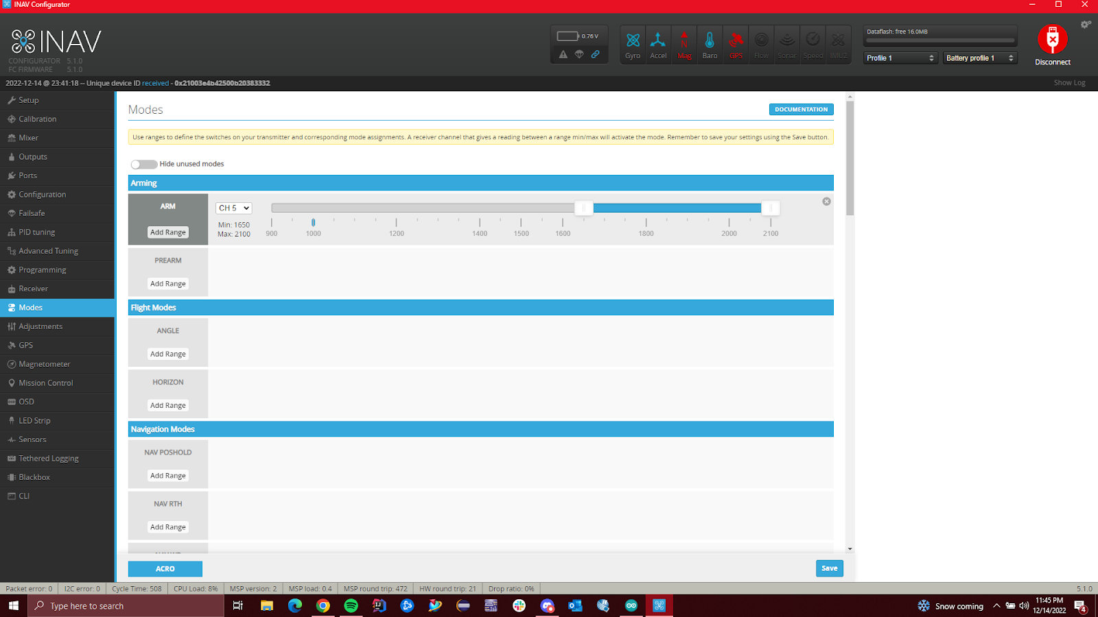
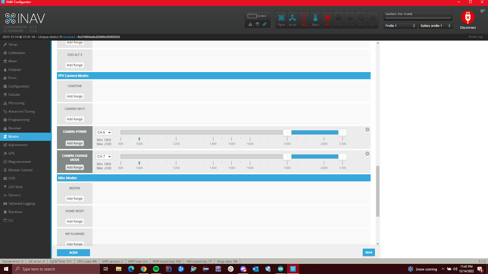
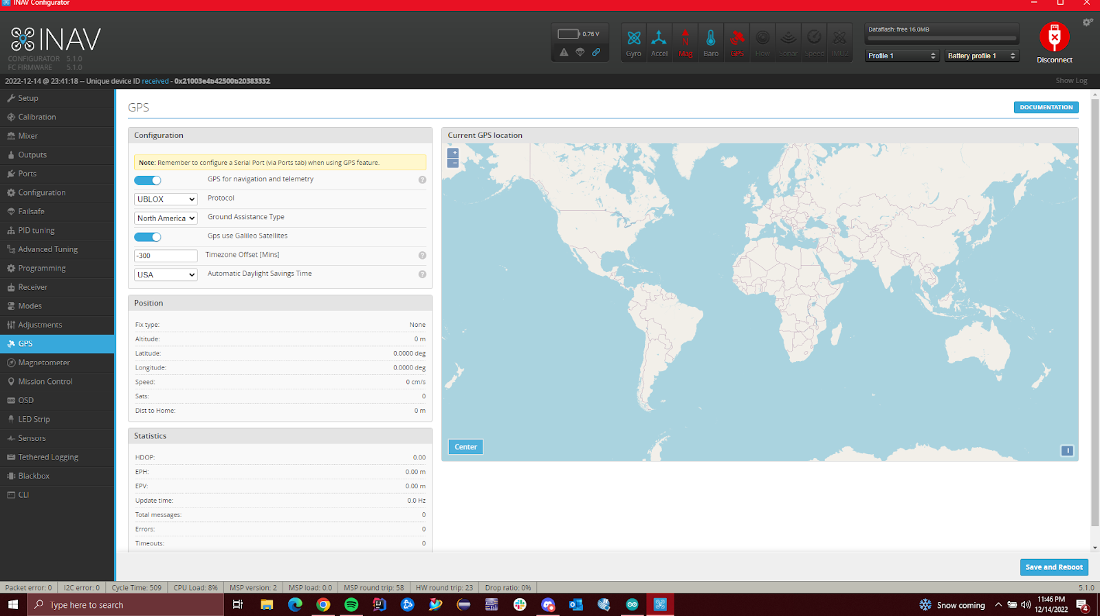
Appendix F: INAV Configurator Settings


Appendix G: Links
Links to everything from open source software, design files, articles used for software development, data sheets, OSF repositories, and more are listed below.