
The Open Source Hardware Enterprise’s Chocolate bar Fabricator Report made by:
Seth Carpenter, Liam Kane, Dylan Bryant, and Alex Olsen
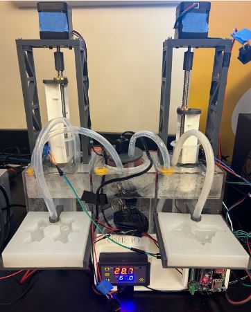
Figure 1: Main Product Image
Description
The Chocolate Bar Fabrication Assembly, or ChocoFab, is a powered chocolate bar processor that takes pure chocolate substances, melts it through a heated tank, and extrudes a predetermined amount of chocolate automatically into custom made silicone molds. The purpose of this project is to allow for open-source custom chocolate bar production for personal and small project use.
The CocoFab Chocolate Assembly Line was created to make ingesting chocolate even more fun; By melting the chocolate using our hot water tank and extruding the melted chocolate into custom molds with unique dropins, we create a more uniquely Michigan Tech piece of candy.
Methodology
Going over the Bill of materials will reveal how few items are really needed for this project outside of a 3D printer. After the 3D printed materials are heat sensors and the controller, as well as the acrylic tank that holds the full project. The power supply for the project only cost around $19 while the acrylic tank cost over $50, easily making it the most expensive part of the bill of materials. There are also electrical components such as Arduinos to control the chocolate excursion, and stepper motors to extrude the chocolate. Most of the tools used in this project are software tools used for CAD or a multitude of slicers to change those CAD models into Gcode for the 3D printers. We also did some light soldering for our circuits to hook up the arduino to the stepper motors so soldering tools are greatly recommended but not strictly necessary. We also made extensive use of our enterprise’s 3D printer and filament for our 3D printed parts of the project.
Electronic Design Process
The electronics design started with an initial idea of needing stepper motors to control plunger depth. A preliminary design was then created, with the plan being to use an Elegoo Mega to control two A9488 stepper drivers which then control the steppers. The prototype for one stepper controller was created on a breadboard (using an Arduino Uno, as it was readily available) to test functionality of the circuit. This prototype is shown below:
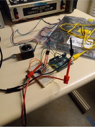
Figure 2: Prototype Electronics
After verifying circuit functionality, efforts were made to move the circuit to a stepper shield that could be plugged directly into the Elegoo. However, there was a shortage of digital input pins on the shield that meant critical buttons and limit switches could not be plugged in. The design was then changed to the breadboard circuit but soldered onto the protoboard to create a more permanent circuit. The original idea of using an Elegoo for the controller was replaced with an Arduino Nano due to the Nano’s compact design. Below is an image of the inside of the unfinished circuit:
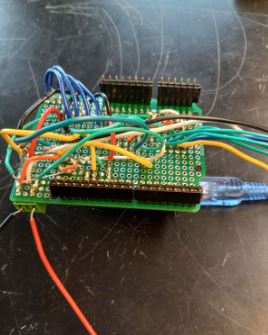
Figure 3: Inside View of the Unfinished Circuit
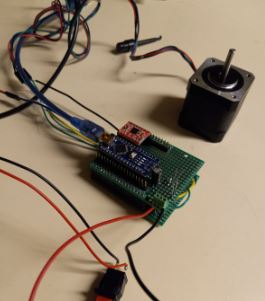
Figure 4: Outside View of the Unfinished Circuit
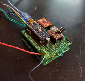
Figure 5: Finished Electronics
Resource, Reference, And Tools Table:
| Link | Description | Use |
| https://www.milwaukeetool.com/Products/Power-Tools/Drilling | Milwaukee Drill | Drilling out holes in the tank to make access points for a multitude of hot water and chocolate tubes. |
| https://ultimaker.com/software/ultimaker-cura/ | Slicer used for non-lulzbot printers | 3D printer slicer used for printing with lab and personal printers. |
| https://lulzbot.com/support/cura | Cura slicer for lulzbots | 3D printer slicer used for printing with lab printers via USB or SD card. |
| https://www.autodesk.com/products/inventor | Autodesk Inventor Student 2023 | CAD software used to make both molds, lead screw assembly, mx in device, pump components, and other structural components. |
| https://www.onshape.com/en/ | Onshape | CAD software used to make new parts to cast silicone molds. |
| https://www.freecad.org/downloads.php | FreeCAD | CAD software used to develop the electronics housing. |
| https://www.lakechamplainchocolates.com/making-chocolate/ | Article from Lake Champlain Chocolates on how to make chocolate from cacao beans | Good information if future plans lead to the creation of chocolate from raw cacao beans. |
| https://www.ecolechocolat.com/en/how-chocolate-is-made.html | Article from Ecole Chocolate on how chocolate is made from the bean to the bar. | Good resource if future plans lead to the creation of chocolate from raw cocoa beans. |
| https://www.whitakerschocolates.com/blog/what-are-the-food-additives-in-chocolate/ | Article from Whitakers Chocolates, elaborating about most of the common food additives, and their use in chocolate. | Good resource if future plans lead to the creation of chocolate using a custom recipe with different additives. |
Bill of Materials
| Component | Part/Identification Number | Price xQuantity |
| Husky Mold V3 | link | $0.10 x1 PLA Estimate |
| OSHE Mold V3 | link | $0.10 x1 PLA Estimate |
| StepperFrame_V1 | link | $0.10 x4 PLA Estimate |
| StepperFrameTop_V1 | link | $0.08 x2 PLA Estimate |
| PlungerMountTop | link | $0.02 x2 PLA Estimate |
| SyringeHolder | link | $0.04 x2 PLA Estimate |
| CenterTankLid_V2 | link | $0.04 x1 PLA Estimate |
| PumpSplitter_V3 | link | $0.02 x1 PETG Estimate |
| HoseAttach | link | $0.02 x4 PETG Estimate |
| MoldHolder_V2 | link | $0.10 x2 PLA Estimate |
| EndAttach | link | $0.04 x2 PLA Estimate |
| Stepper_to_Leadscrew | link | $0.02 x2 PLA Estimate |
| Electronics_housing-Body | link | $0.50 x1 PLA Estimate |
| MixInTankAdapter | link | $0.05 x1 PLA Estimate |
| MixInTank | link | $0.10 x1 PLA Estimate |
| MixInTankB | link | $0.04 x1 PLA Estimate |
| MixInTankFlip | link | $0.02 x1 PLA Estimate |
| Double Sided Tape | link | $6.49 x1 |
| Acrylic Tank | link | $54.99 x1 |
| Plastic Syringe | link | $7.99 x1 |
| 1 Meter Tube | link | $8.99 x1 |
| 12 Volt Heater | link | $13.51 x1 |
| 12 Volt Power Supply | link (Used lab excess power supply, this is an available option) | $18.99 x1 |
| 14 Gauge Wire | link (Used lab supply, this is an available option) | $18.47 x1 |
| 24v temperature controller | link | $4.04 x1 |
| 5A Fuse switch | link | $7.99 x1 |
| Stepper Motor 2A 48mm Body 4-Lead W/ 1m Cable and Connectors | link | $13.99 x2 |
| Arduino V3 | link | $15.99 x1 |
| Silicone Tubing Food Grade | link | $8.99 x1 |
| 32 Oz Silicone Mold Kit, Food-Grade Silicone for Mold Making | link | $22.88 x1 |
| Clay | link | $12.99 x1 |
| Petroleum jelly | link | $3.97 x1 |
| The amazing remelt | link | 0.00 x1 |
| uxcell 150mm Steel Screw Rod | link | $11.89 x1 |
| Quickun Pure Silicone Tubing | link | $7.59 x1 |
| A9488 stepper driver | (Obtained from lab) | $0.00 x 2 |
| Arduino Nano | (Obtained from lab) | $0.00 x1 |
| Screw terminal | $0.00 x1 | |
| 100uF capacitor | $0.00 x2 | |
| 10k resistor | $0.00 x2 | |
| Perf board | $0.00 x2 | |
| Push button | $0.00 x2 | |
| Limit switch | $0.00 x2 | |
| Type-B USB | $0.00 x1 | |
| 12PCS SG90 Micro Servo Motor | link | $16.99 x1 |
Assembly Instructions:
Tank and Mold Holder Assembly
- Download all 3d printed parts from the OSF repository in the Spring2024 file and print all of the parts in whatever material you would like besides “HoseAttach.stl” and “PumpSplitter_V2.stl” which should be printed in PETG to prevent leaks.
- Unscrew the rods from all three chambers then drill out the holes with a ⅜ drill bit to make room for the new tubes. Make an additional fourth hole in the center right as well. Discard the small orange tube and the rods.
- Attach one end of the tube to the end of the syringe and run the other from the inside of the tank to the outside through the hole we drilled larger previously.
- Take the SyringHolder and slide it over the syringe body. Next, cut the top 15mm off of the plunger and glue PlungerMountTop on top.
- Slide the lead screw into the hole, and screw two screws into the part from the bottom into the lead screw nut as shown.
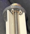
Figure 6: Lead Screw Visual Aid
- Next attach Stepper_to_Leadscrew to the top of the lead screw using hot glue to assure it does not spin in the hole.
- Next screw StepperFrameTop_V1 onto two StepperFrame_V1’s to form the structure for both of our steppers. Next screw a stepper motor into the top, and glue both legs of the frame onto opposing sides of the circular cutout in the tank, centering it to the best of your ability.
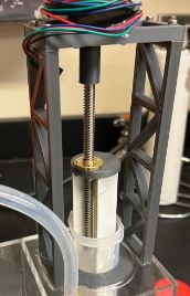
Figure 7: Assembled Frame
- Push the other side of the Stepper_to_Leadscrew part onto the stepper so that your final assembly matches the one above.
- Repeat steps 3-8 for the other side of the tank.
- Glue 1 EndAttach to each of the MoldHolder_V2 parts facing outwards from the back so the tube will be held over the mold. Then glue this assembly to both the right and left tanks about 4 inches up from the bottom.
- Slot the heater into the 3d printed center tank lid and put it facing downwards into the tank.
- Drill four ½ inch holes in the back of the tank, 1 on each side, and 2 in the center tank.
- Using bathtub sealer or other caulk, distribute caulk on the fitting and press the 4 tube connectors into the holes from the inside of the tank. Then cut two sections of tube and hose clamp the tubes to the connectors so that tank one is linked to tank two, and tank two is linked to tank three.
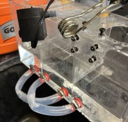
Figure 8: Inter-tank Tubing
- Put the tube splitter into the pump and attach one tube to each side of the splitter. Run one tube through each of the drilled holes on the top center tank. Run one tube back into each side tank on the left and right to circulate the hot water and place the pump in the bottom of the center tank.
Optional Mix In Add On
- Get 1 MixInTankAdapter, 1 MixInTank, 1 MixInTankB, and 1 MixInTankFlip per mix in containers you want. Place the flap on the inside of the container, then screw the servo into place on the lower portion, making sure the flap fits over the output shaft. Glue the MixInTankB to the bottom center of MixInTank (this part was split in two for ease of 3d printing).
- Glue the assembly onto either the top of the tank or onto the side of the StepperFrameTop_V1 then run a tube to whichever mold you want to add the mix-ins too.
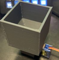
Figure 9: Mix-in Tank
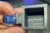
Figure 10: Mix-In tank with attached Motor
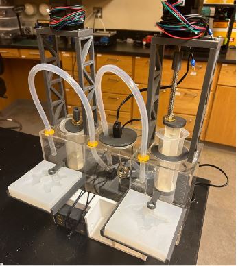
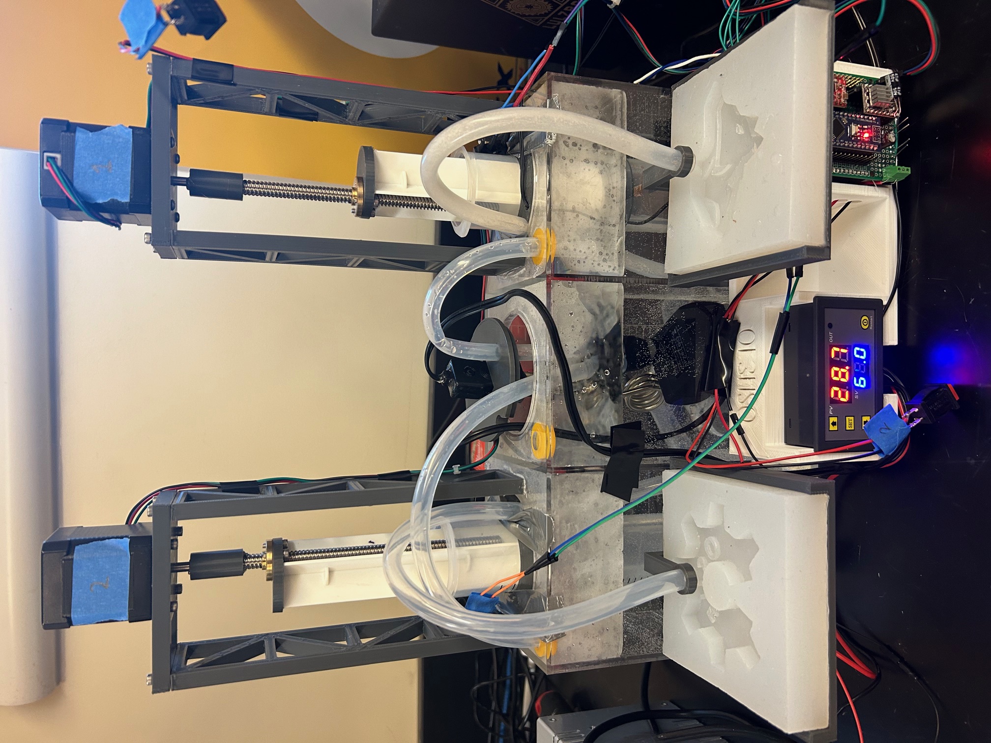
Figure 11: Assembled Fabricator
Heater and Controller Assembly
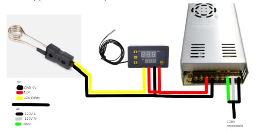
Figure 12: Heater and Controller
- Cut the cigarette lighter plug off the 12 volt car water heater and strip ¼ inch of the plastic of the positive and ground wires.
- Open heating element. Fill the heating element with JB weld epoxy. Close the element while epoxy is setting. This makes the heater waterproof.
- Connect one wire from the heater to ground, the other to the relay on the temperature controller. (Either wire works, this is a non-directional part.)
- Connect the 12v to both Vcc and the other relay connection on the temperature controller with 14 gauge wire. Connect the temperature controller to ground with 14 gauge wire.
Arduino and stepper assembly
- Gather 2 perf boards, one Arduino Nano, two A9488 stepper motor drivers, two 100uF capacitors, two buttons, two limit switches, male and female headers, one pair of screw terminals, two 10k resistors and 22 gauge wire. Also have a soldering iron ready.
- Upload the code onto the Arduino using a type-B USB cable.
- Cut the male and female headers to match the number of pins on the Arduino and A9488. This will make it easy to remove and replace them in the event that one burns out or makes it easy to recycle them into another project. Plug them into the top of the first perf board.
- Turn the perf board upside down and solder the header pins so they are secure. Then, construct the following circuit by soldering 22 gauge wire to make the connections. Note that this shows the BACKSIDE of the perf board, so we are looking at the bottom of the Arduino and A9488. In this image, the USB on the Arduino and the potentiometer screw on the A9488 is facing up. The red dots represent the pin footprint of the A9488, the blue dots represent the pin footprint of the Arduino. The green wires going off-screen connect to the stepper motor connections, the teal and blue wires going off screen connect to the limit switch, and the teal and yellow wires going off screen connect to the button.
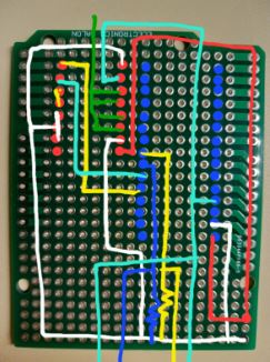
Figure 13: Backside of the Perf Board
Figure 14: Top of the Perf Board
Note that the red and black wires coming out of the screw terminal are 12V and ground, respectively, and should be connected to the 12V voltage supply.
- A perf board is then attached below the first one using headers as a spacer. This assembly can now be inserted into the electrical casing.
Silicone Mold Assembly
- Print the 3D models of the two different Chocolate molds, which can be found in our repository. Both of these molds are 20.5 mm in total height and make chocolates that are 8 mm in height. The part-to-end thickness, or the thinnest thickness of the silicon molds, is 12.5 mm, or about 1/2 an inch, so the molds are strong enough to automate the extraction of the chocolates from the molds.
- Use clay to fill in all the gaps and imperfections from your 3D print. A thin flathead screwdriver is recommended for this.
- Test the molds’ integrity by casting them with Amazing Remelt Material. In addition to testing the mold’s integrity, the Amazing Remelt Material will fill any gaps or holes missed beforehand with Clay. If your Amazing Remelt Test went well, it’s time to make your silicone molds.
- Use a paintbrush, paper towel, or similar tool to spread Vaseline/Petroleum jelly over the entire mold. This will make it easier to extract the silicone mold later.
- The Husky mold needs 187.33 mL to make its silicone mold, and the OSHE mold needs 181.65 mL. Measure 1/2 of the volume of the silicone Part A solution and 1/2 of the volume of the silicone Part B solution (these should be 1:1). Mix these together, then pour them into the 3D-printed mold for the mold. Stop at the fill line.
- (Optional) Put each newly poured mold into a vacuum chamber to remove excess bubbles before the silicone mold cures.
- Let the newly poured mold cure at room temperature for 3-4 hours. The silicone mold should fully cure at this point.
- Use a wedge tool to peel the newly created silicone molds out of their 3D-printed shells. You now have chocolate molds for the OSHE Logo and the MTU Husky Logo!
The general operation of the project is quite simple. First you load chocolate into both the right and left syringe and turn the heater on. After the chocolate has melted insert the mold you would like to use below the tube. Next, push the button once to fill the husky mold with chocolate or twice to fill the OSHE logo. Once the chocolate has cooled it is ready to be removed from the mold and consumed!
Acknowledgements
We would like to acknowledge Beau Ujlaky from Tools Toys Technology (@toolstoystechnology on IG) for helping with the 3D printing and silicone mold casting process. He provided consultation on the 3D printing process and helped manage issues that arose during our prints, and provided his experience in silicone mold casting to help our team make custom food safe silicone molds. His company Tools Toys Technology plans to bring the future of toys and tools into today using STEM, but also has aspects in 3D printing, and many other fields.
The Team
Past Members
Links to More About our Project