
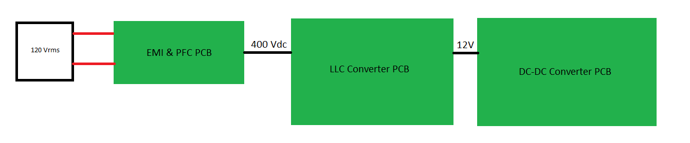
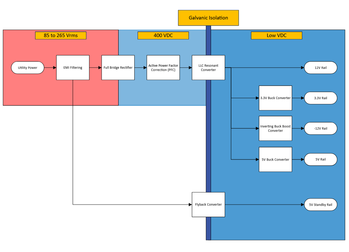
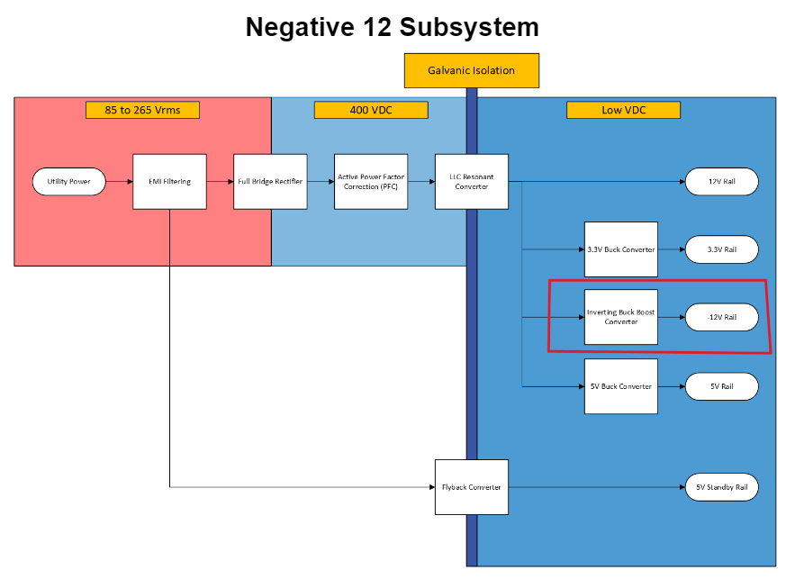
9/23/23 – This week we finalized our system architecture shown in the flowchart below:

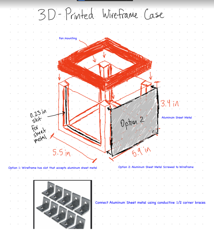
This upcoming week we will be focusing our efforts on case design and a comprehensive AC-DC conversion simulation in QSpice. Below are the 2 case designs we are looking to prototype this upcoming week.
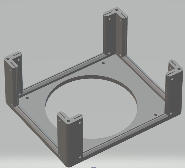
10/28/2023 – 3D-printed case has been finished. Ran into problems during print. The current model has too long of a print time and needs to be printed over night (not allowed). Plan for next week is to make case for ‘modular’ to print.

11/4/2023 – Looking into LLC Converter evaluation boards and seeing what are best option is. We are still debating on whether to go with the cheaper, half-bridge UCC25640EVM-020 module or the all-in-one and more expensive PFCLLCSREVM034 Board.
Spring 2024
1/27/2024
Project Sketch
To-do list
- Review and Change Project Spec
- Design Expo Signup
- -12V Topology research
- Have a first draft for 3D printing
Concerns
- No concerns so far
2/3/2024
To-do list
Last Week
Review Change Project Spec– Completed- Design Expo Signup – 75% Done, on-hold until layout for project showcase
- –
12V Topology research– Completed 3D Print First Draft– Completed
This Week
- Merge McMasterCarr CAD models into 3D Print Draft
- Find Inverting Buck Boost IC and put into a schematic
2/10/2024 – To-do List
- Merge McMasterCarr CAD models into 3D Print Draft – Not complete, did not have time with Winter Carnival
- Find Inverting Buck Boost IC and put into a schematic – Found White paper with IC recommendations but have not ported an IC into a schematic
2/16/2024 To Do List
Merge McMasterCarr CAD models into 3D Print Draft – CompletedFind Inverting Buck Boost IC and put into a schematic – Completed
Next Week
- -12V Schematic Finalization aka Footprint selection & Calculation double-checking
- Slides for CDR
- Revise 3D print & reprint case design + order hardware needed
2/24/2024 To-Do List

Find Inverting Buck Boost IC and put into a schematic – CompletedMerge McMasterCarr CAD models into 3D Print Draft – Completed-12V Schematic Finalization aka Footprint selection & Calculation double-checkingSlides for CDR- Revise 3D print & reprint case design + order hardware needed
- Start routing for -12 V PCB
3/9/2024 To-Do List
- Was able to revise 3D print, holding off on ordering hardware because we are not using the case
- Holding off on PCB routing until our group can do a Schematic review with Chris from Plexus
- Currently working on a schematic review document that should be ready by next week
3/17/2024 Updates
- This week we have concentrated on making a schematic review document for Plexus to review. We are still continuing to work on it and are finishing it up at the beginning of the next week.
- For the -12V subsystem, a document has been made that shows the schematic, engineering intent, and where the -12V subsystem resides in the overall system architecture.

- For next week, we’ll be aiming to wrap up the schematic review document and start on some basic layout for the -12V board.
3/22/2024 Updates
- We wrapped up the schematic review document which can be seen here. It shows our overall system architecture, schematic design, and engineering intent behind our design.
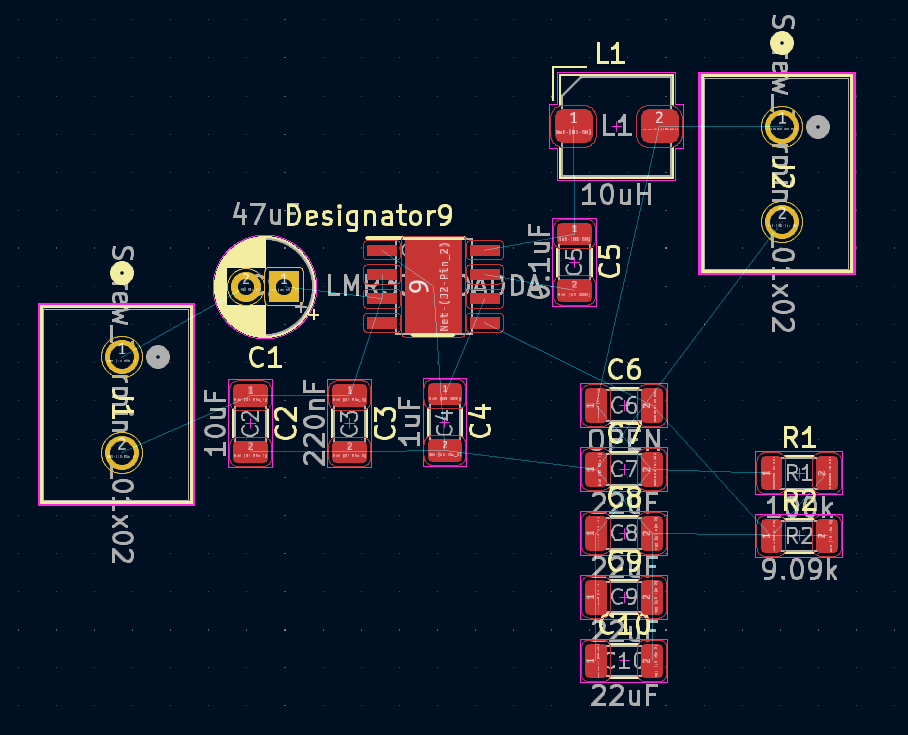
- This week I have been starting the -12V board layout. Still pretty early in its progress, just starting to group components.
3/30/2024 Updates
- This week we went over our schematic review with Chris from Plexus. He gave us some good insight into our schematic design
- Regarding the PCB design, we ended up going with a 4 layer board to simplify some of the routing issues we were having. This also means redoing a lot of the layout that we were working on. Currently, I have completed the preliminary layout and am on the routing stage.
4/6/2024 Updates
- This week, the team finished the PFC, LLC, 5VStandby, & -12V PCB Layouts and Chris was able to review our layouts. We got the green light to order the boards and our parts which was accomplished yesterday. Worst case, we are looking at a shipping arrival date of the Monday before Design Expo.
- The DC-DC PCB Layout still needs work. We plan to merge the -12V PCB with the DC-DC board to reduce PCB fabrication costs. This work is being completed over the weekend to make sure we can order the PCB by this upcoming Monday.
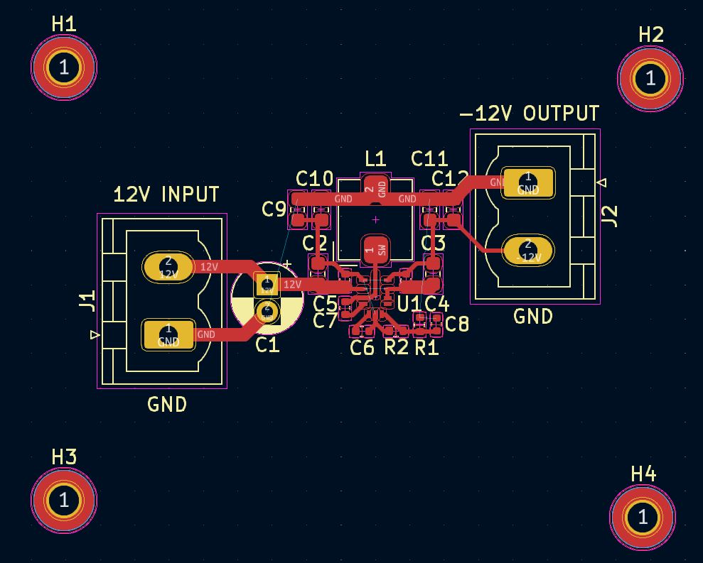
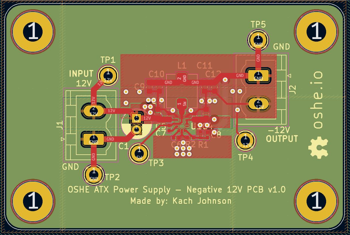
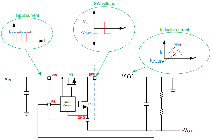
- Below is the -12V PCB Layout which I completed. It is a 4-layer board that uses an Inverting Buck Boost topology with a synchronous buck converter. The IC is a VQFN footprint and uses the GND plane as a heatsink. The footprint and packages are harder to assemble but should aid us in the effort to meet the future ATX footprint requirements.
4/13/2024 Updates
- We are still waiting for our PCBs to arrive. Currently, the worst-case shipping time will be this upcoming Friday. In the meantime, the team has been preparing for the design expo, creating instructional material regarding each of our subsections, and completing sections of our final report.
- For the design expo video, Mitch Krueger recorded us giving a spiel of what the ATX project is. He also captured B-roll footage of us doing our PCB layout.
- For the report, I added sections on why the topology was selected and other general information to know about the design. I found a figure from TI explaining the signal waveforms of the input and output rails from the subsystem. I found it useful and will be using it in our report.
4/21/2024 Updates
- We received some good feedback from Design Expo. The judges liked our pitch but found the use cases for the project to be lacking. When I first picked up the project, I was hoping to make a cheaper version, but with the PCB fab costs, I found that goal out of reach.
- With Ben Abel’s economic evaluation, he found that the parts and PCB fabrication costs amount to around $177 per unit without including the 5V and 3.3V rails and other various hardware needed. That is unreasonably more expensive than what you would find commercially and our design won’t be able to get a UL cert (costs > $20K).
- The main cost from the PCB fab perspective is the copper weights, for most of our designs, 2oz outer weights and 1oz inner weights are required. This adds about 48 dollars to each order of our boards.
- Moving forward, I think the team will have to pivot to an educational-based objective.
- This week, the main focus has been the design expo and exam week. Other than us doing more work on the project’s final report, there are no other updates.