
Restruder 9/17/2023 – 9/23/2023 Updates
One of the issues from last semester that I wanted to improve is the diameter sensor for the Restruder. While looking at the previous diameter sensor, we noticed that the sensor was not performing up to the standard we wanted, and I was tasked with finding an alternative for this sensor.
Prevoius Diameter Sensor
https://www.thingiverse.com/thing:454584
Through doing research, I was able to find an open-source design that used a different type of sensor for our task. The sensor I found was a linear Hall effect sensor with a magnet to measure the diameter of the filament. This was done by attaching the magnet to a lever that was pushed away from the linear Hall effect sensor, and the information could then be used by an Arduino to get fairly accurate measurements. This design focused on low cost and compactness, which are important for the Restruder project.
Current Filament Diameter Sensor
https://www.printables.com/model/57154-infiDANK
I am currently getting the parts of this sensor and assembling the sensor. I am planning to have the sensor assembled by the end of next week. For the next week I am starting to design a containment system for the whole project.
Restruder 9/24/2023 -10/1/2023 Updates
This week I mainly focus on the assembly on the filament diameter sensor. I also got some goals for website development for this website. Which is a new experience for me and I am excited to start. Finally the design for a containment system for the whole project is being taken up by Alex Nigrine.
Printing of the Filament Diameter Sensor
The printing of the filament diameter sensor took longer than I expected. My first prints were using ABS filament in which the process of filing down the filament was difficult and I ended up cracking the print to the point that it was unusable. I decided to switch to PLA filament but I had major difficulty in which either while printing the thickness of the filament coming out was not correct and making them fragile or the print did not stick to the plate. I ended up getting the parts printed correct toward the end of the week.
ABS Print of the Block
In this print some of the holes in the project were filled with filament which was too difficult to remove.
ABS Print of Lever
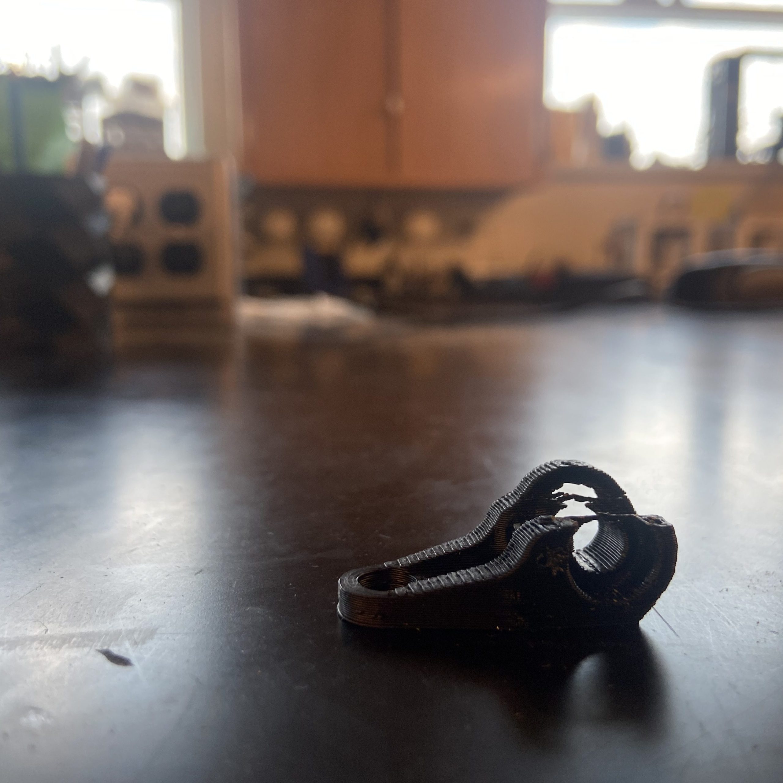
In this print while filing it it ended up snapping the piece in which the part is not unusable.
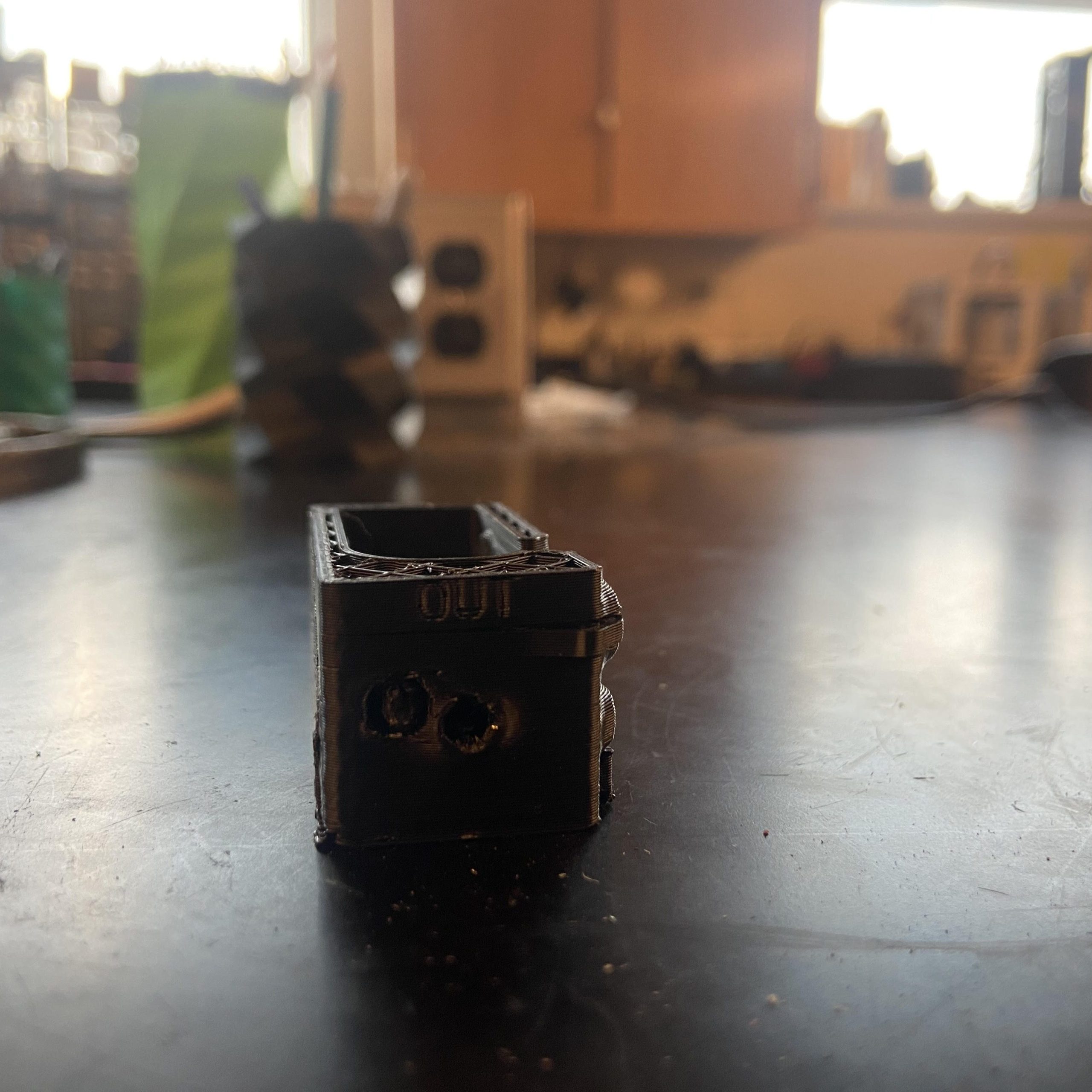
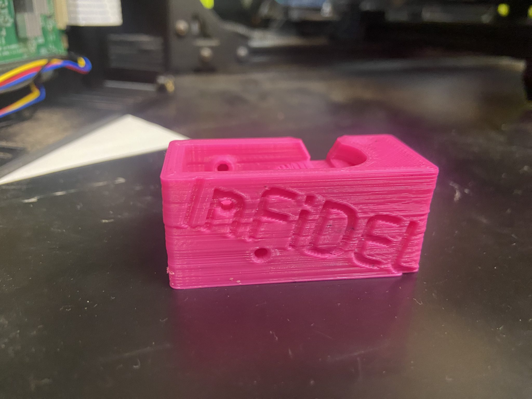
Final PLA Print of Block
The Assembly Process
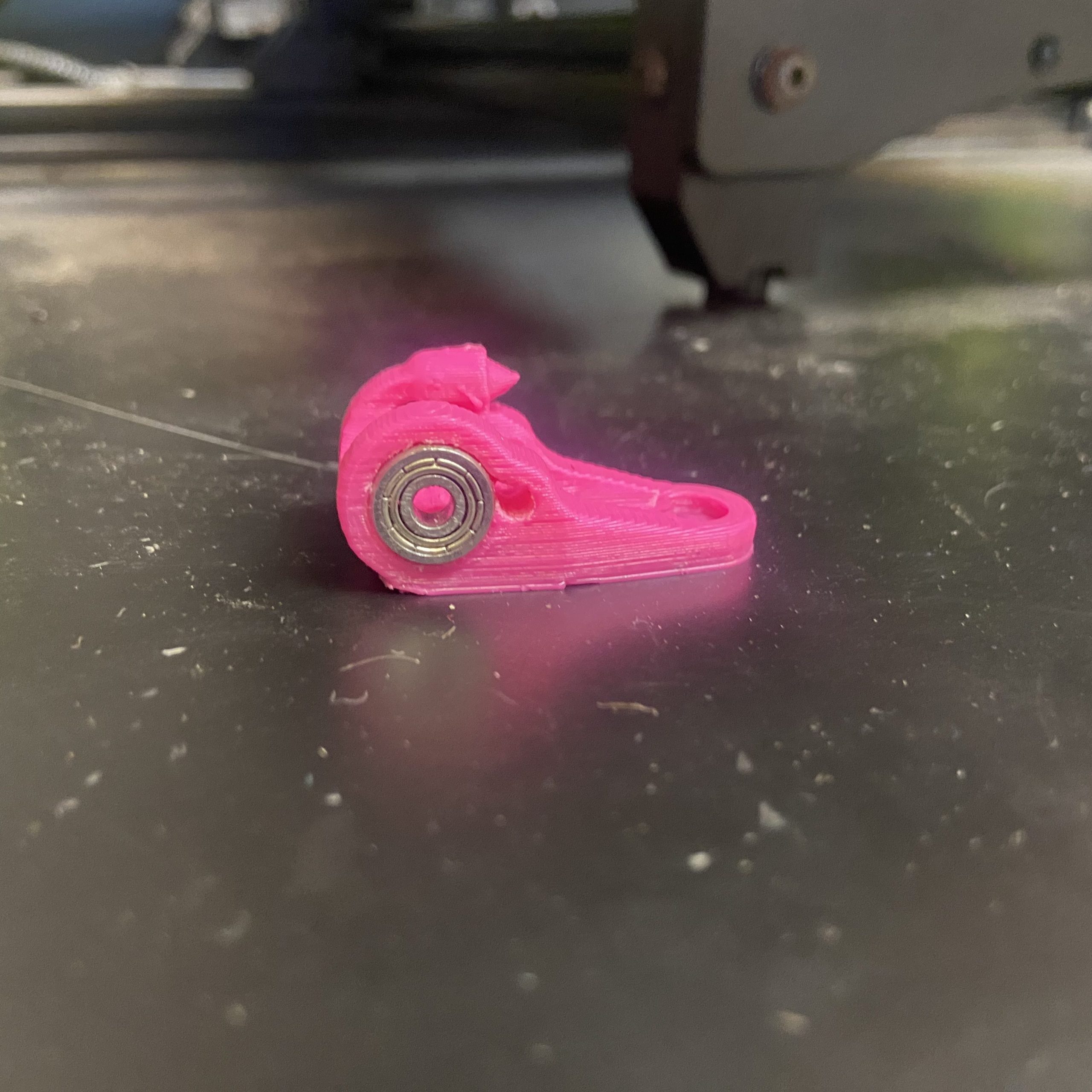
This week I ended up getting some part of the assembly process. In which I put the bearing and pins in the lever of the filament sensor.
Lever with bearings
Goals for Next Week
I plan to finish the sensor this week to use with the whole project. Also in some spare time I have started some website development ideas.
Restruder 10/2/2023 – 10/8/2023 Updates
This week I continued assembly of the filament sensor and getting the final pieces together for the final assembly. I wrote a basic arduino code that reads the linear hall effect sensor and shows it as analog data.
For future use of the arduino code I would need to put an averaging function in and find and calculate the analog data into a diameter length.
Goals for Next Week
I would like to fully assemble the filament sensor and start working on the arduino code to have it more useful for the project.
Restruder 10/9/2023 – 10/15/2023 Updates
This week I was able to get the filament diameter sensor fully assembled and was able to get some updates for the Arduino script for it.
Fully Assembled Filament Diameter Sensor
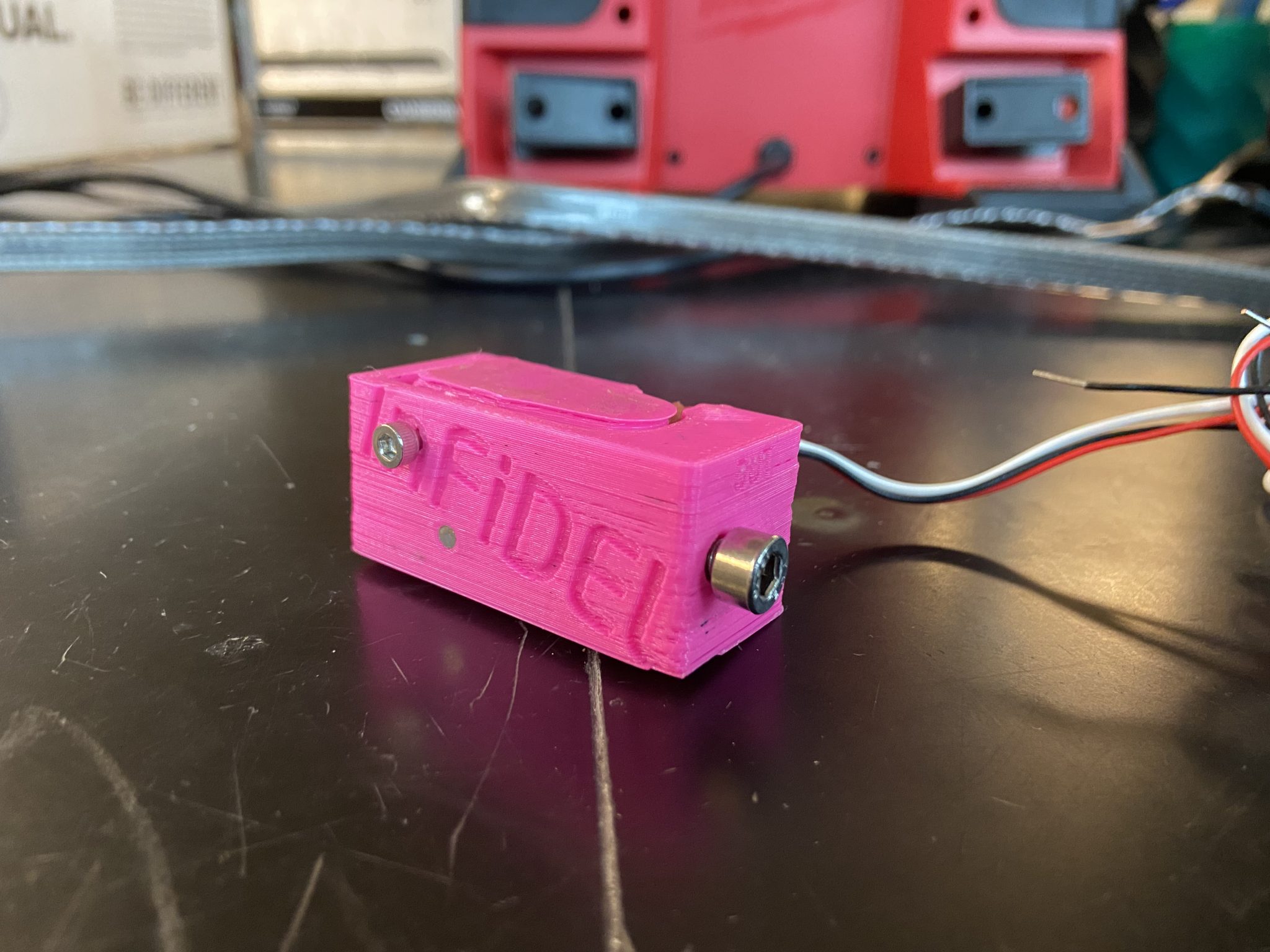
I made the decision to put a screw instead of a pin for attaching the lever to the body to make it removable in case the lever breaks. The linear hall effect sensor is glued to the body of the sensor.
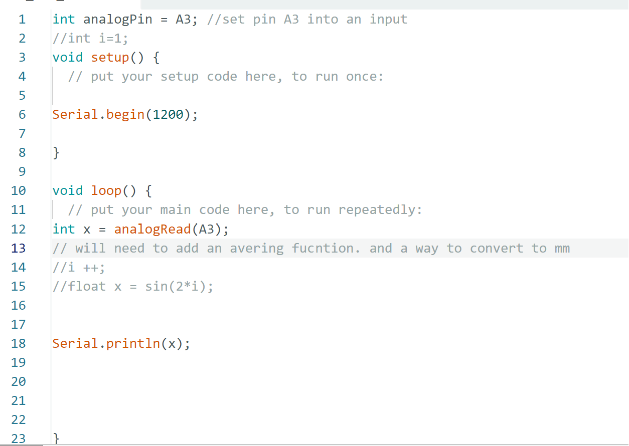
Code
With the Arduino code I updated the code using parts of the Infidel sensor code that could be found here. The code that I have now can take filament diameter reading but I would need to go and test if it is accurate enough.
Arduino Code
int analogPin = A3; //set pin A3 into an input
// set up final data
float dia;
// Declare the function before loop
float converter(float x) {
// This is where the math is done
//converts an ADC reading to diameter
//Inspired by Sprinter / Marlin thermistor reading
byte numtemps = 2;
const float table[numtemps][2] = {
//{ADC reading in, diameter out}
//CALIBRATION ONLY
//(unless you want to do the lookup on your host)
{ 0 , 0 },
{ 1023 , 1.023 }
};
byte i;
float out;
for (i = 1; i < numtemps; i++)
{
//check if we've found the appropriate row
if (table[i][0] > x)
{
float slope = (table[i][1] - table[i - 1][1]) / (table[i][0] - table[i - 1][0]);
float indiff = (x - table[i - 1][0]);
float outdiff = slope * indiff;
out = outdiff + table[i - 1][1];
return out;
}
}
// Return a default value if no suitable value is found
return 0.0; // or any default value you prefer
}
void setup() {
// put your setup code here, to run once:
// define speed of serial
Serial.begin(1200);
}
void loop() {
// put your main code here, to run repeatedly:
float x = analogRead(A3);
dia = converter(x);
if (dia > 0.70 && dia <0.75){
dia = 0;
} else {
dia = dia + 1.1;
}
Serial.println(dia);
// short delay
delay(1000);
}
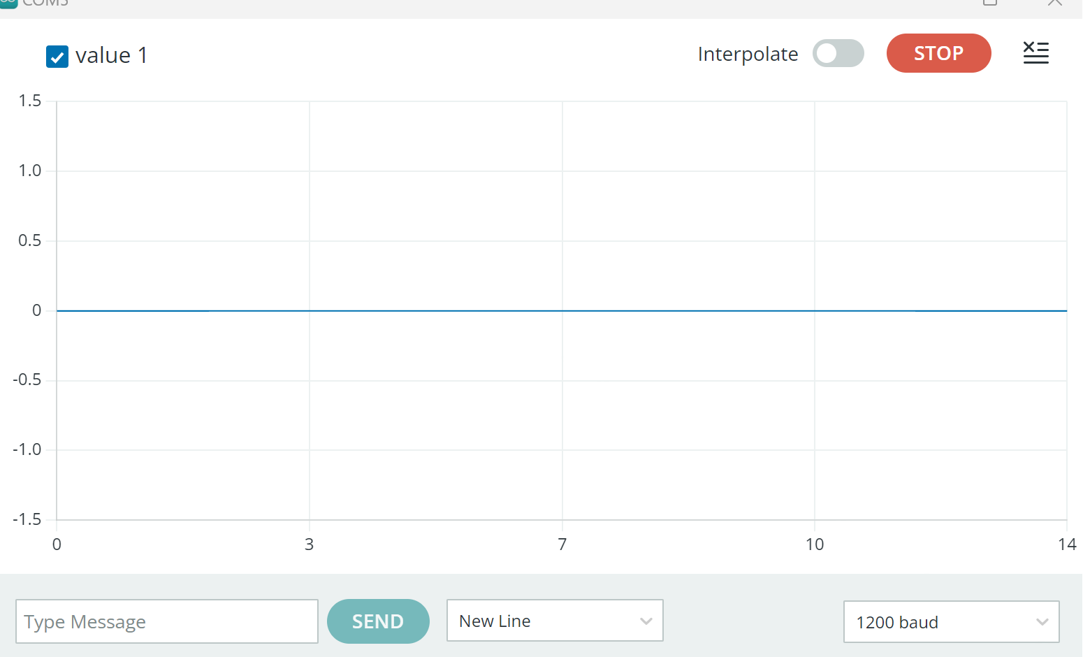
// measurement given out in mmSerial Plot When No Filament is in
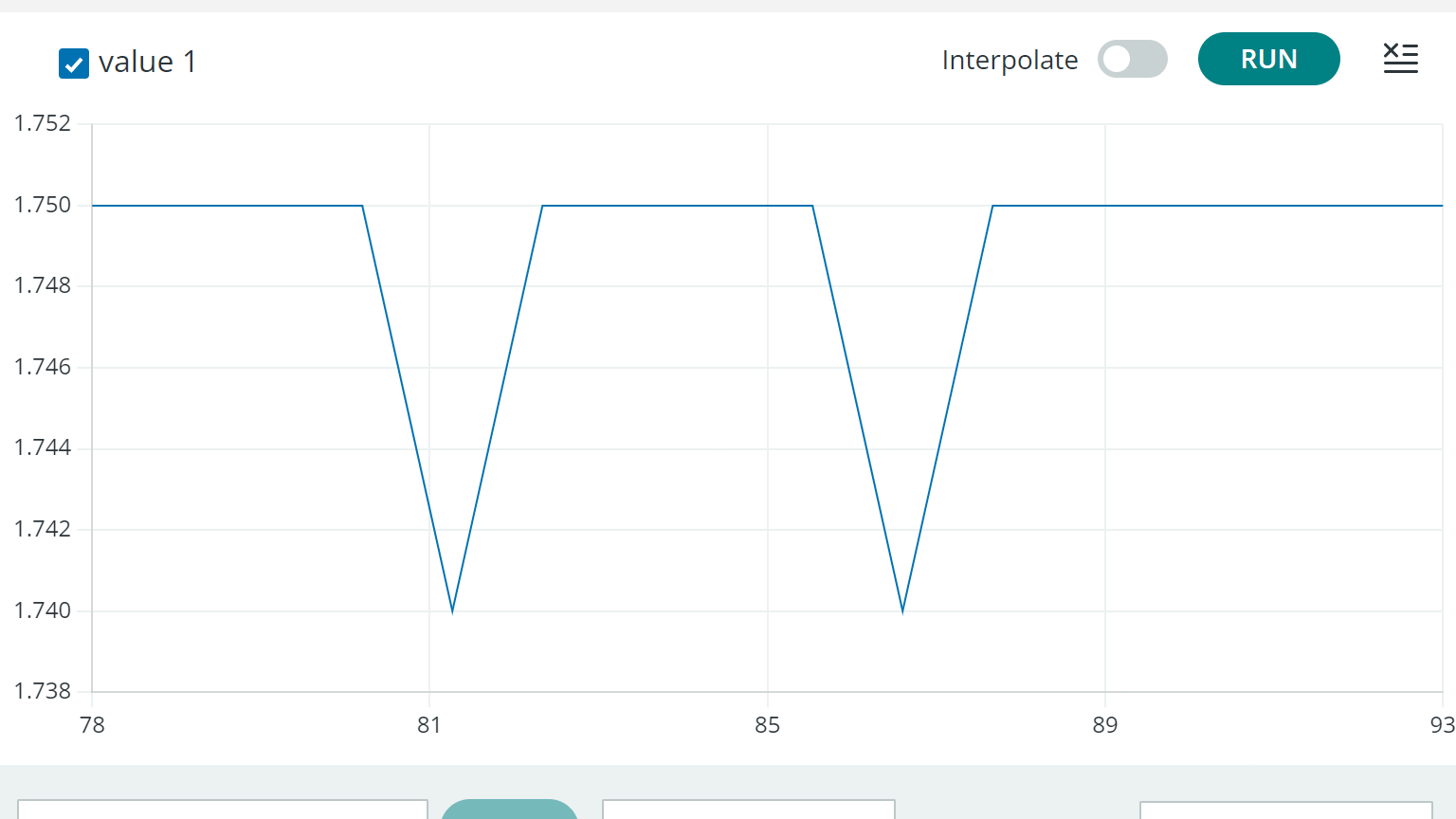
Serial Plot when 1.75mm
Restruder 10/15/2023 – 10/22/2023 Updates
This week I mainly was working on the Arduino script that is used to convert an Analog input to an reading in mm. I was mainly looking at in the converter function if the const float table in there could be changed to make it more accurate to the system and to be able to not use the if statements I put in. In the next week I will be still working on the code to be able to find a better response to the sensor.
My Current Code
int analogPin = A3; //set pin A3 into an input
// set up final data
float dia;

// Declare the function before loop
float converter(float x) {
  // This is where the math is done
  //converts an ADC reading to diameter
  //Inspired by Sprinter / Marlin thermistor reading
  byte numtemps = 2;
  const float table[numtemps][2] = {
    //{ADC reading in, diameter out}
    //CALIBRATION ONLY
    //(unless you want to do the lookup on your host)
    {682 , 1.50},
    {741  , 0}
  };
  byte i;
  float out;
  for (i = 1; i < numtemps; i++)
  {
    //check if we've found the appropriate row
    if (table[i][0] > x)
    {
      float slope = (table[i][1] - table[i - 1][1]) / (table[i][0] - table[i - 1][0]);
      float indiff = (x - table[i - 1][0]);
      float outdiff = slope * indiff;
      out = outdiff + table[i - 1][1];
      return out;
    }
  }
  // Return a default value if no suitable value is found
  return 0.0; // or any default value you prefer
}

void setup() {
  // put your setup code here, to run once:
  // define speed of serial
  Serial.begin(2400);
}

void loop() {
  // put your main code here, to run repeatedly:
  float x = analogRead(A3);
  dia = converter(x);
  //if (dia > 0.73 && dia <0.75){
    //dia = 0;
 // } //else {

   //if(dia > 0.60 && dia <0.73)
    //{
    //  dia = dia * 2.69231;
    //}
    //if(dia > 0.50 && dia <0.60)
   // {
     // dia = dia * 5.55556;
    //}
  //}
   Serial.println(dia);
   //Serial.println(x);
  // short delay
  delay(1000);
}
Restruder 10/22/2023 – 10/29/2023 Updates
This week I have been updating the code to get the filament sensor a better response to the input data. I was using drill bit heads for calibration and got the code functional to a certain extent.
const int analogPin = A3; // set pin A3 into an input
float dia;

float converter(float x) {
  byte numtemps = 5; // Update the number of rows in the table
  const float table[numtemps][2] = {
    //{ADC reading in, diameter out}
    //CALIBRATION ONLY
    //(unless you want to do the lookup on your host)
    {536, 3},
    {610, 1.984375},
    {644, 1.75},
    {683 , 1.5875},
    {743  , 0}
  };
  byte i;
  float out;
  for (i = 1; i < numtemps; i++) {
    if (table[i][0] > x) {
      float slope = (table[i][1] - table[i - 1][1]) / (table[i][0] - table[i - 1][0]);
      float indiff = (x - table[i - 1][0]);
      float outdiff = slope * indiff;
      out = outdiff + table[i - 1][1];
      return out;
    }
  }
  return 0.0; // or any default value you prefer
}

void setup() {
  Serial.begin(2400); // define speed of serial
}

void loop() {
  int numSamples = 10; // Number of samples to average
  float total = 0; // Initialize the sum of samples
  for (int i = 0; i < numSamples; i++) {
    total += analogRead(analogPin); // Add each sample to the total
    delay(10); // Delay between each sample reading
  }
  float averagedValue = total / numSamples; // Calculate the average

  dia = converter(averagedValue);
  //Serial.println(dia);
  Serial.println(averagedValue); // Print the averaged analog reading
  delay(100); // short delay
}
In the updated code there are a couple things that change. First I removed the if else statement and when to edit the float table in the converter function. These values that I change to is the analog value to the mm values to help with the calibration. This was done by using a couple of drill bits and taking the raw analog value. I also added an averaging function since I noticed there was some noise in the sensor and I wanted to reduce that to get more consistent values.
Goals for Next Week
For next week I want to test my code accuracy and I want to look into if the resolution of the sensor could be changed through code. I also want to work on some of the websites and make progress on that.
Restruder 10/29/2023 – 11/5/2023 Updates
This week I mainly looked into the accuracy of the filament diameter sensor code. This was done to see if the sensor was accurate enough to be able to and to see if I could improve the accuracy. I ended up changing the calibration of the code to improve the accuracy of the sensor. I ended up getting a consistent error of + or – 0.02 mm. Which is an improvement from before.
Current Calibration that I Gotten
float converter(float x) {
  byte numtemps = 6; // Update the number of rows in the table
  const float table[numtemps][2] = {
    //{ADC reading in, diameter out}
    //CALIBRATION ONLY
    //(unless you want to do the lookup on your host)
    {536, 3},
    {566, 2.31},
    {600, 1.98},
    {638, 1.72},
    {694 , 1.58},
    {743  , 0}
  };
Goals for next week
Next week I want to be able to help out with the integration of my code with the rest of the system code and be able to test some filament with the stepper moving at the appropriate rate.
Restruder 10/29/2023 – 11/5/2023 Updates
This week I mainly worked on the development of the OSHE website. I am also working with Alex Nigrine on the implementation of the 3d model on the mounting of Restruder.
Goals for next week
Next week I want to be able to help out with the integration of my code with the rest of the system code and to be able to help with the physical mounting system for Restruder.
Restruder 11/19/2023 – 12/3/2023 Updates
I was mainly focused on updating the stl file for the 3d model of the mounting of the Restruder. In which I added a spot for the filament diameter sensor to be attached to.
Model that I edited
Then I worked on printing the part which caused a lot of issues. When first editing the file the file got corrupted and created a shell instead of a solid part. which made printing have a couple of air gaps and snapping easily. This was not notice until a later point but when the issue got found, it have gotten fix.
The print with the sensor attached to it
Restruder 12/03/2023 – 12/10/2023 Updates
This week I focus on working on the final report to get our project ready to be completed by the semester. I also finished the website development. I am also working on the final touches for the final check of the project.
Restruder 1/21/2024 – 1/27/2024 Updates
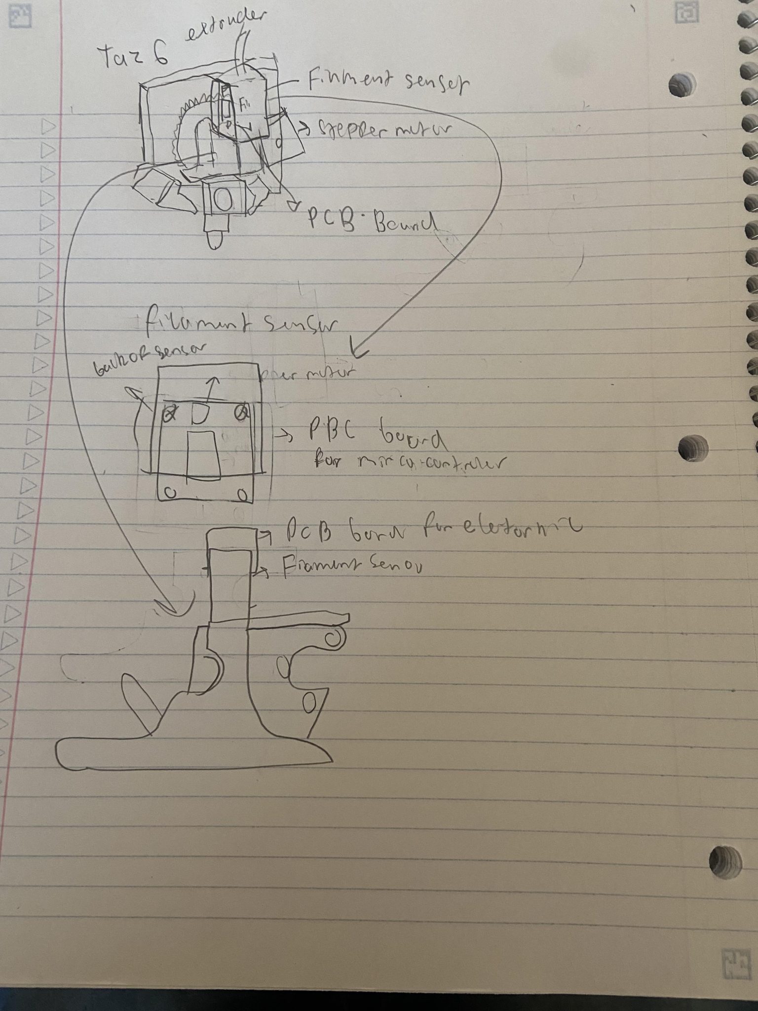
These past couple of weeks I have been focusing on getting caught back up to speed with Restruder, and getting a reviewing last semester goal and updated them for a better well defined scope of the project. After a long discussion we have decided to implement Restruder on a Taz 6 3d printer with a fully swappable extruder system. We wanted to make a fully swappable extruder system because when we were going to test our system to the 3d printer we did not want to go through and break one of the printers that everyone uses while attaching and detaching our system to it. The Restruder actual pieces will still however can be transferable from different printers. Our goal for this semester is to get a testable restruder system going for others to gather data on.
Final Design Idea Sketch
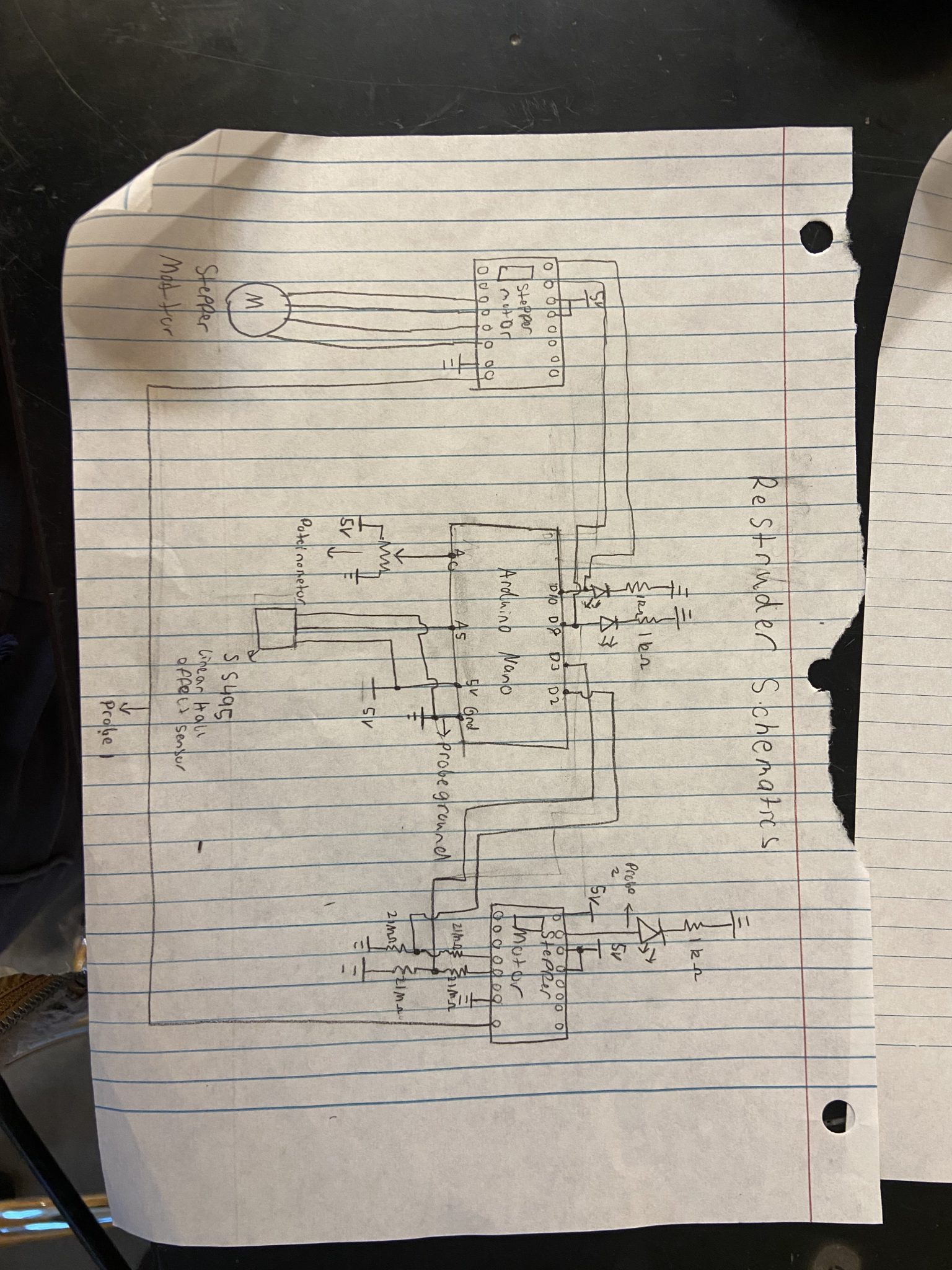
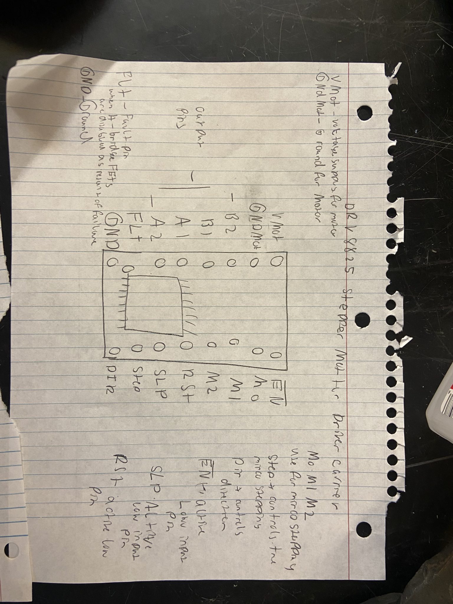
Current Circuit Schematics
Goals for the Upcoming Week
I am going to be mainly responsible for the mechanical design for the extruder and getting that up and running as soon as possible. The first thing I would have to do is to get the BOM of the Taz 6 extruder to see all the necessary parts. All of the documents of the Taz 6 3d printer could be found here. In the previous semester there was an extruder mostly built. We are planning to use that to cut costs and to save time. Then I would go through and see what is missing and start printing on any missing part and order part.
Concerns
I am a little worried for next week that the parts we are going to need are going to go above our budget. I am also concerned that going through the documentation is going to take longer than necessary and hold us up a little bit.
Restruder 1/28/2024 – 2/3/2024 Updates
This week I mainly was going through the documentation that could be found here. In which I moved the BOM for the Luzbot Taz 6 and was looking at the extruder system we had. Turns out the extruder system that we had from previous semesters was a KitTaz 3d printer. In which we were able to receive a Luzbot Taz 6 from a printer that was no longer being used in this enterprise.
My Goals in for the semseter (so far)
- Attach our extruder assembly from last year to the extruder of the Luzbot Taz 6
- See if there are any issues with the current design of the extruder assembly
- Design a way for a circuit board could be attached to the system
Goals for Next Week
Next week I will be focusing on attaching our part to the extruder assembly and see if there are any issues with it and make changes if so.
Restruder 2/4/2024 – 2/10/2024 Updates
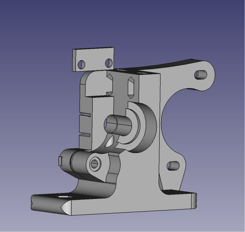
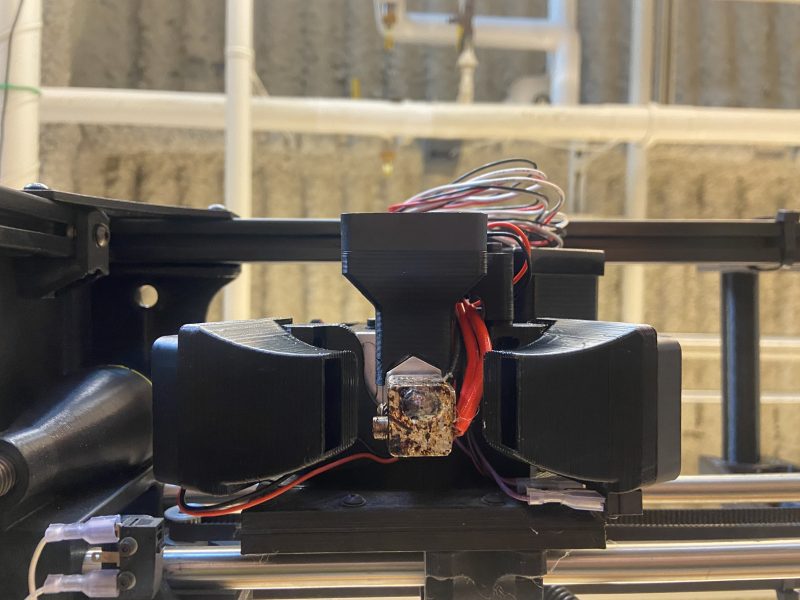
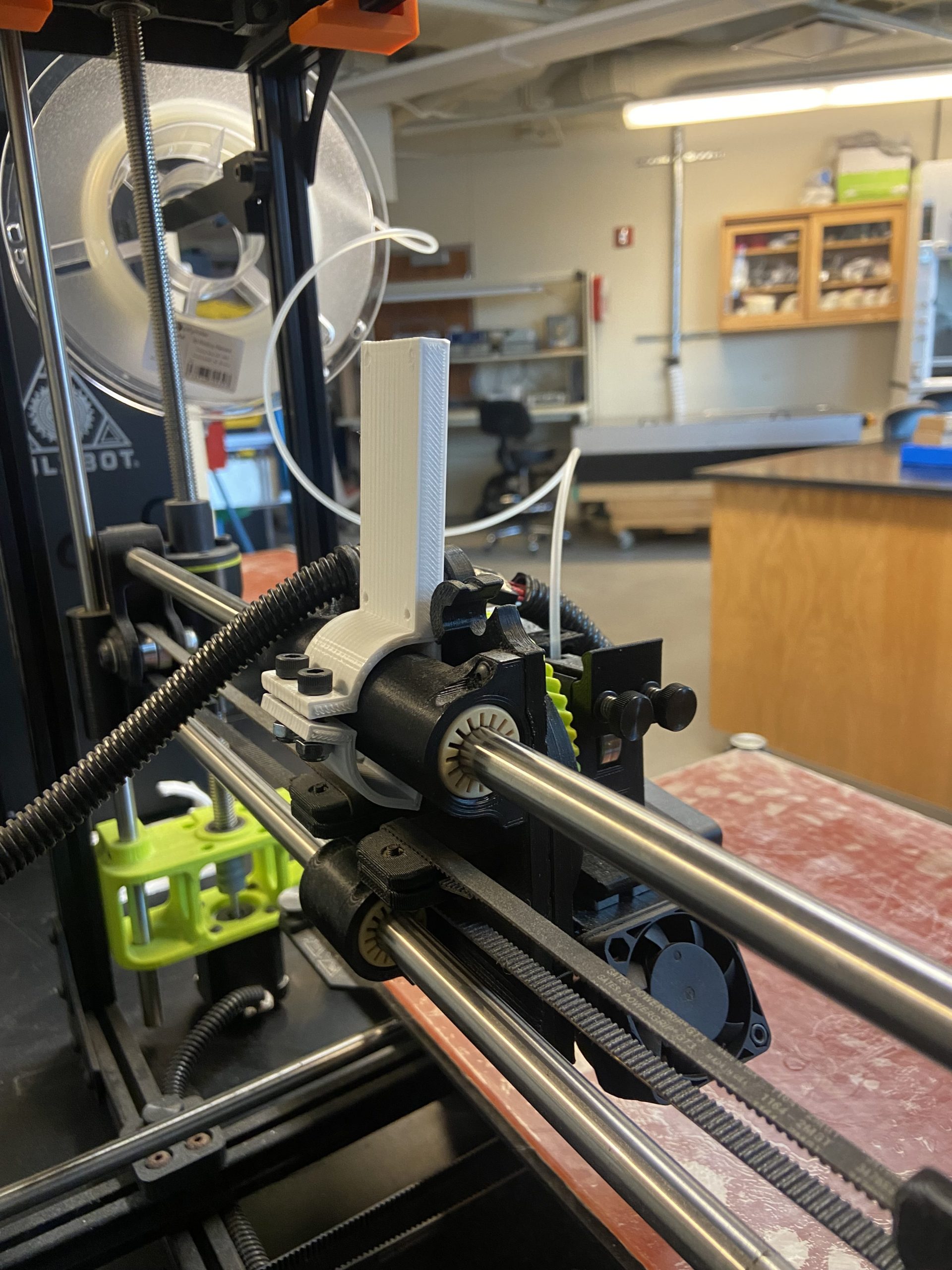
This week I went and disassembled the Luzbot Taz 6 extruder and tried to attach our design for the assembly. There was an issue in which the sensor was getting in the way of the extruder assembly. in which the sensor will have to be up higher so the bolts will not get into the way of the 3d printer extruder assembly.
New Extruder Design
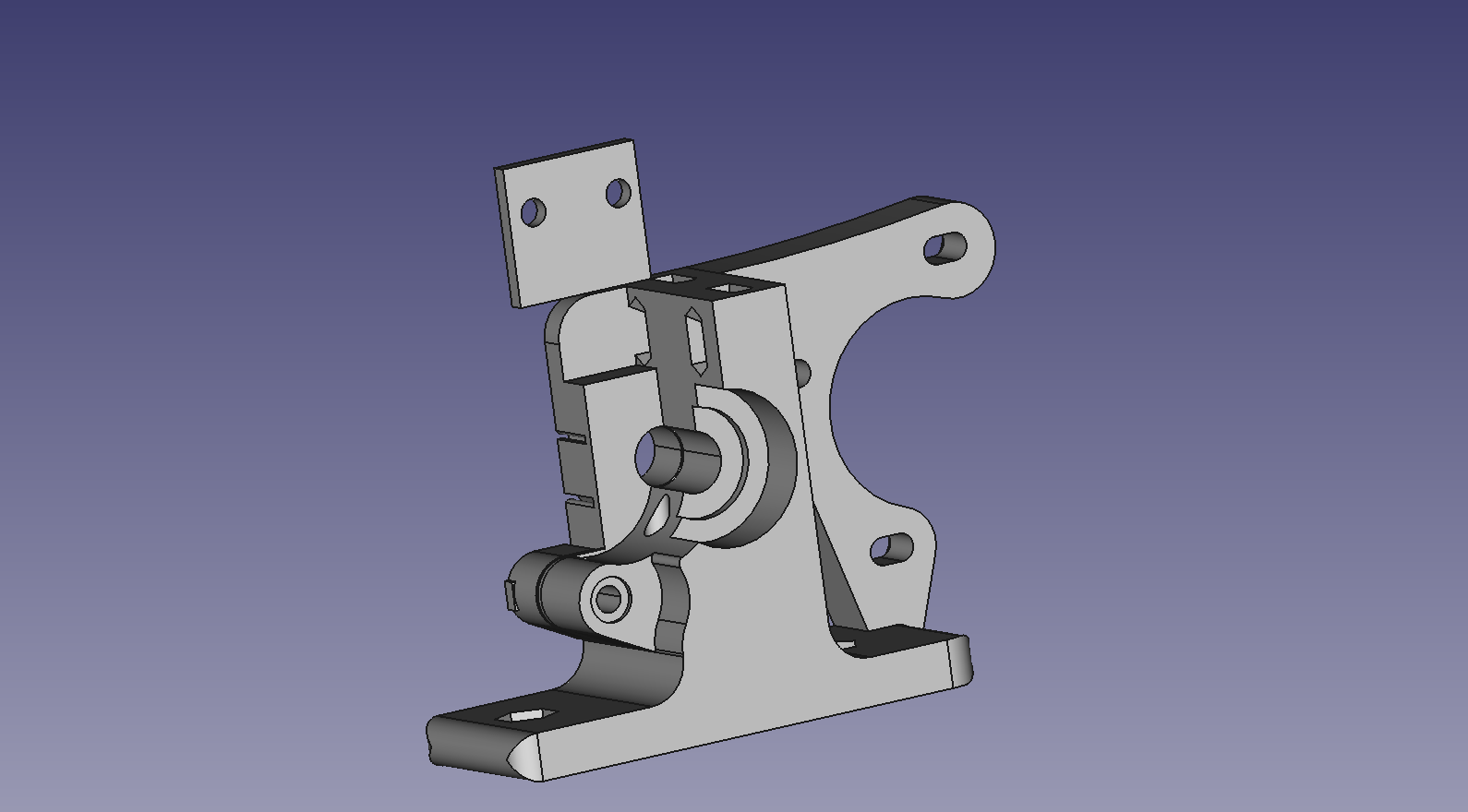
In which I have been trying to print this for the rest of the week. There have been a lot of struggles with printing this. I had had a lot of failed prints while trying to print this. There is an issue where the filament is curling and after changing settings it continues to fail the print. My Goals for the semester at this point.
Goals for the semester
- Attach our extruder assembly from last year to the extruder of the Luzbot Taz 6
- Print out of the current redesign of the sensor attachment
- Design a way for a circuit board could be attached to the system
Goals for next week
Next week I am going to print this piece out and attach it to the extruder assembly.
Concerns
I am a little concerned that I will not be able to print the part out and will continue to spend much more time than needed to print out this part.
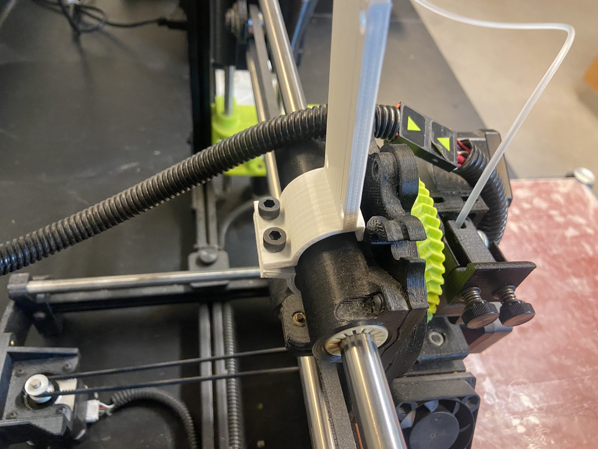
Restruder 2/11/2024 – 2/16/2024 Updates
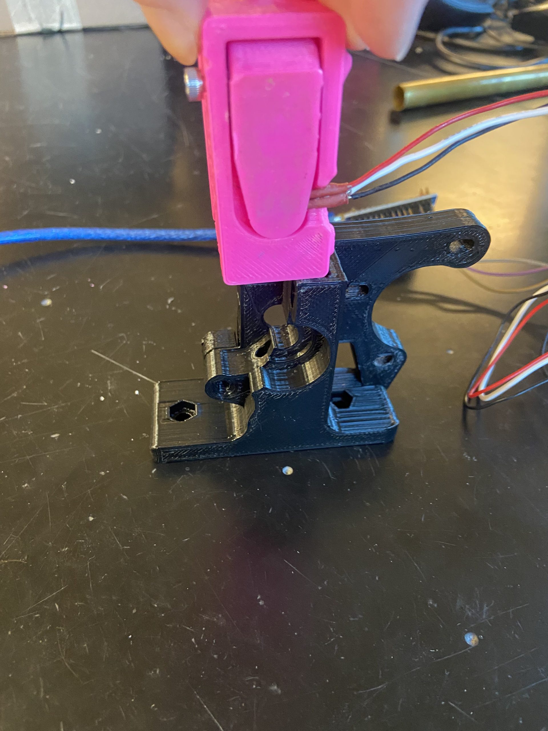
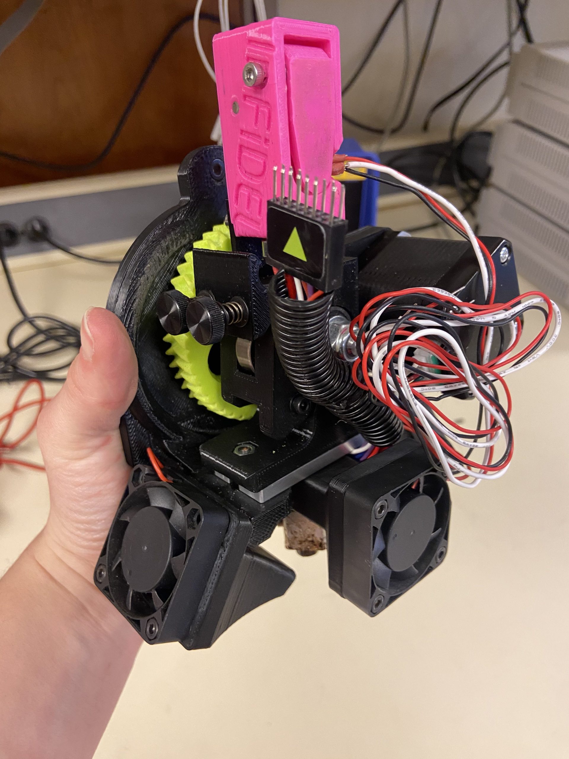
This week I printed out the new extruder design and focused on the reassemble of the extruder system. With the sensor being attached there the printed gear is having issues with moving with the sensor attachment bolts being on there. So I added a washer for a spacer so that the gear could move freely, otherwise I did not change the LuzBot Taz 6 extruder system design.
Reassembled Extruder system
Goals for the semester
- Attach our extruder assembly from last year to the extruder of the Luzbot Taz 6 (done)
- Print out of the current redesign of the sensor attachment (done)
- Design a way for a circuit board could be attached to the system
- Test the sensor system to see if there are any issues
Goals for next week
Next week I am going to be focusing on providing a test in which nothing is changed with the extruder except for the sensor being there and see if there are any issues with the sensor being attached to the system.
Concerns
I am concerned that the test would take up too much time and I will not be able to get it done in time.
Restruder 2/16/2024 – 2/24/2024 Updates
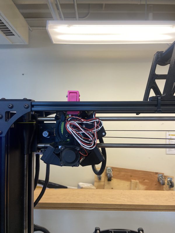
This week I have done some initial testing with the extruder assembly. In which I did three tests which are movement, filament insertion and removal, and a test print. The movement test that was conducted was to be able to move the 3d printer to the maximum x, y, and z values to see if the sensor is going to cause interference with the 3d printer. I also did a movement test in which filament is inserted into the 3d printer. The filament insertion and removal was to see if the extruder system could be able to insert and remove filament with no issues. I also did a test print to see if there were any issues with the extrusion rate.
Movement
With the extruder system attached to the 3d printer there were no issues with movement. However there are some concerns with the extruder system. With the sensor being attached there is now a new maximum height of the extruder system in which the sensor was going above the frame of the 3d printer. This would mean that with this system would have to have nothing on top of the printer so that the sensor can not interfere with the printer.
Also, the wiring would have to be managed and maintained since when the printer heads towards the maximum value of z the room in front of the extruder is very little.
Filament
This test went fine however a few considerations needed to happen. Since the sensor can only handle filament from 1.5 to 2.5 mm of diameter, the recommended diameter for the Lulzbot Taz 6 is 2.85mm this could not be inserted into the printer any more. Also when the filament is inserted, the extruder end up pumping out filament even though there are no commands to do so. This might cause problem in the future.
Test print
In this test I put a small rectangle for the 3d printer to print out in which I used 1.75mm diameter filament and changed the setting for the G-code to have it print 1.5mm diameter of filament. There were a lot of problems with printing. There was a lot of inconsistency with the extrusion rate. Which made many prints fail. Next week I am going to test with a different extruder to see if there is a problem in general or is it the extruder assembly.
Goals for next week
Next week I am going to be focusing on providing a test for printing with a different extruder assembly and fixing the issue with the printer or the extruder.
Concerns
I am concerned that the test would take up too much time and I will not be able to get it done in time. Also I am worried about the integration of the rest of the electrical components.
Restruder 3/3/2024 – 3/9/2024 Updates
This week unfortunately I have gotten really sick and was unable to do much this week. This week I was setting social media requirements and a submission form with Liam Kane for this semester. Next week I want to get our extruder system to print a part out with only minor issues. I will test print with a different extruder system to give my test some control. I will also be starting to design a way to have our electrical system. After our design critical review there was an idea of putting it on the back of the extruder using velcro.
Goals for the semester
- Attach our extruder assembly from last year to the extruder of the Luzbot Taz 6 (done)
- Print out of the current redesign of the sensor attachment (done)
- Design a way for a circuit board could be attached to the system
- Test the sensor system to see if there are any issues (in progress)
Restruder 3/10/2024 – 3/16/2024 Updates
This week I finished our initialization testing for our extruder system. I have printed out a couple of test prints and everything worked out fine. I did a control print from an already working printer and I did two test prints from our extruder system. In the picture below the control print is labeled C and the test prints are T1, and T2. There is some inconsistencies with the printing that are unknown. Between T1 and T2 there are some differences even though the printer settings are the same. This could be from the filament I was using and the print was affected by that.
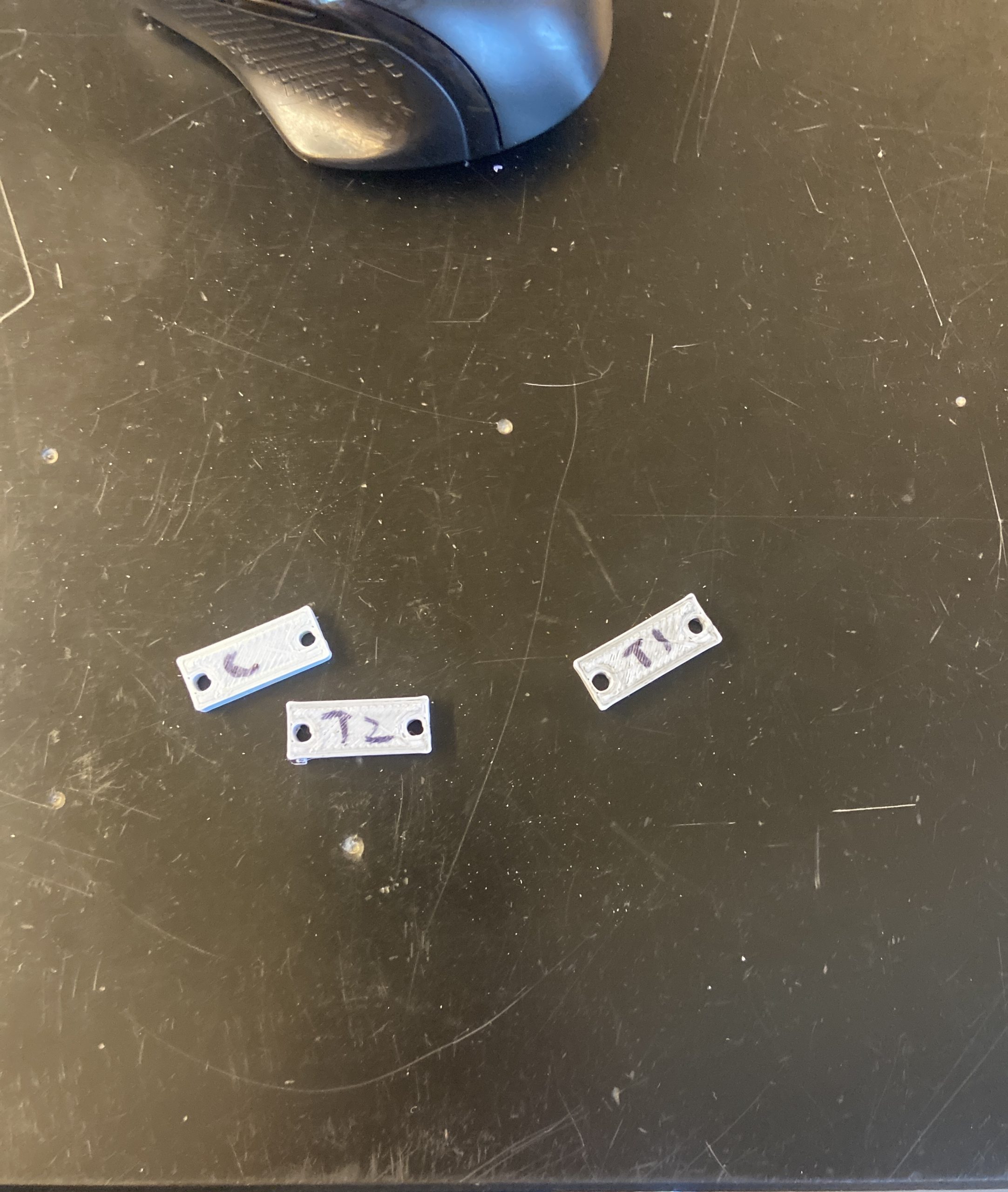
Test and control prints
The next thing I am working on is designing the part for the PCB board. I am designing a snappable part that would be attached to the back of the Lulz Taz bot 6. On the back there is a nice bracket that has no belts and gears that would get in the way of the part. The only thing that would have to be considered is the wiring management with our parts and our extruder system.
Back of Luz Bot Taz 6
My Goals for the semester
- Attach our extruder assembly from last year to the extruder of the Luzbot Taz 6 (done)
- Print out of the current redesign of the sensor attachment (done)
- Design a way for a circuit board could be attached to the system (in progress)
- Test the sensor system to see if there are any issues (done)
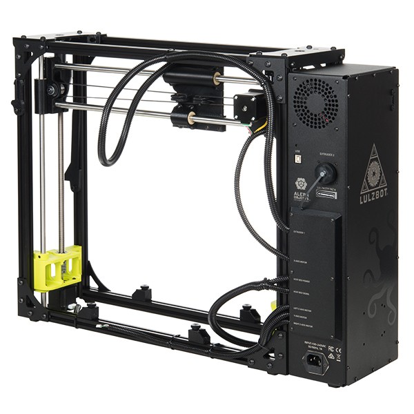
Restruder 3/17/2024 – 3/24/2024 Updates
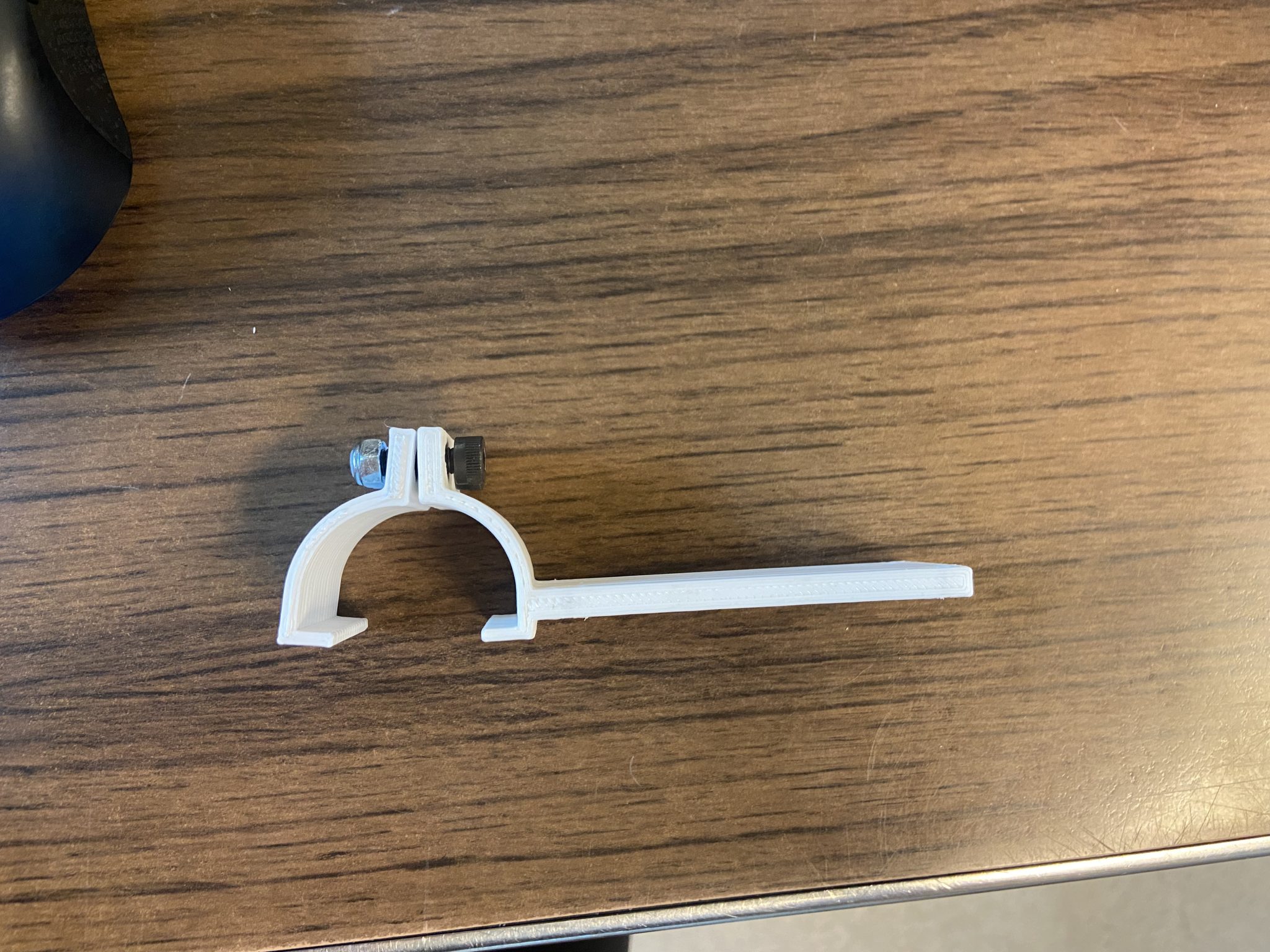
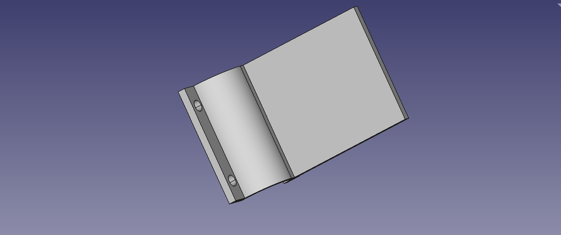
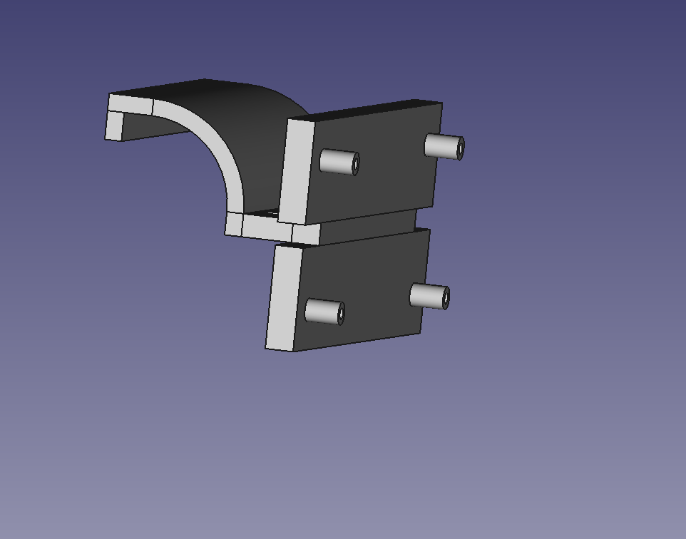
This week I mainly worked with designing the part that will attach the 3d printer. With this I am currently testing the design that I have will have enough force to hold the pieces together to the back of the 3d printer. A change of design was made between this week and last week. After a discussion, the snappable part was going to be hard to do since the 3d filament is not really flexible and hard to move around once printed properly.
Current design
In this design I have two parts in which they would clasp around the back of the 3d printer in which a bolt and net will provide an amount of tension to hold them together. The parts designs could be found on the osf site. Next week, I will be testing and updating the design.
My Goals for the semester
- Attach our extruder assembly from last year to the extruder of the Luzbot Taz 6 (done)
- Print out of the current redesign of the sensor attachment (done)
- Design a way for a circuit board could be attached to the system (in progress)
- Test the sensor system to see if there are any issues (done)
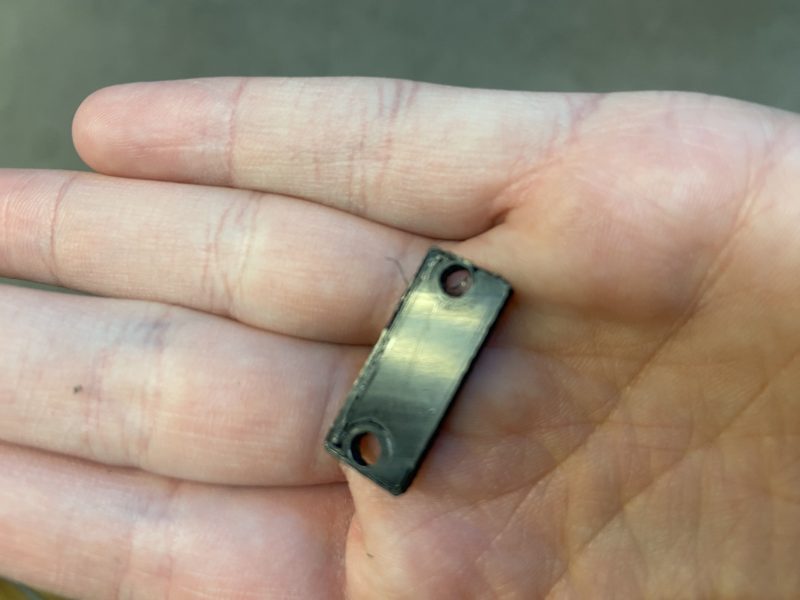
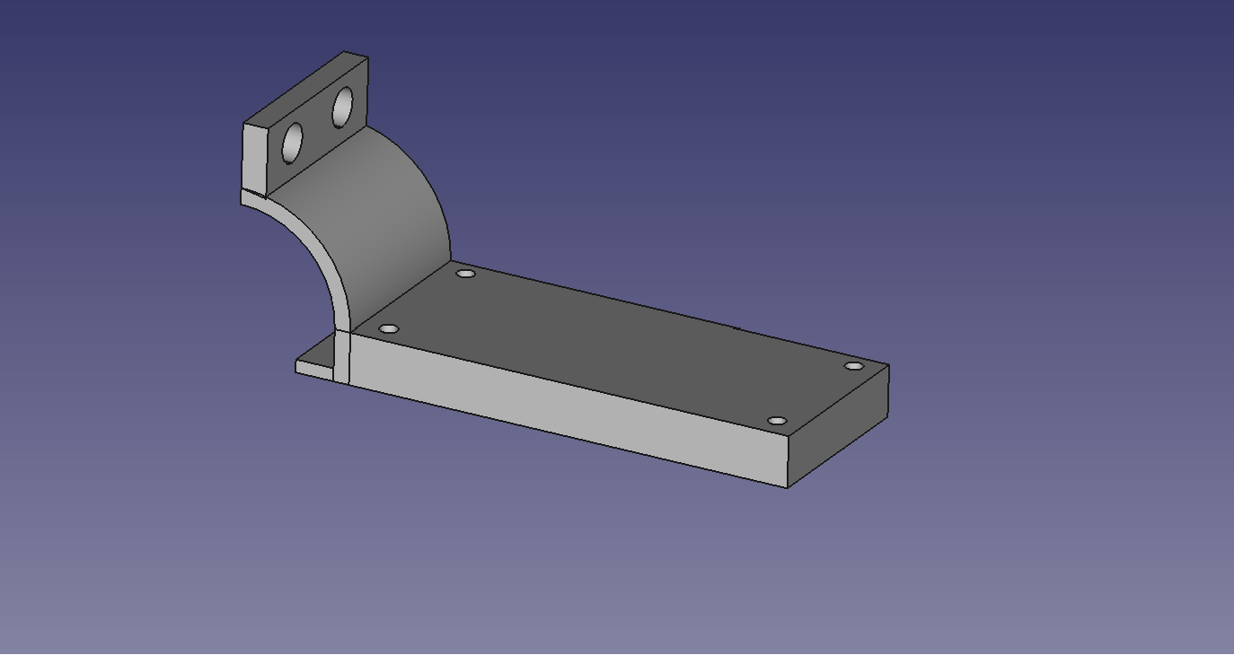
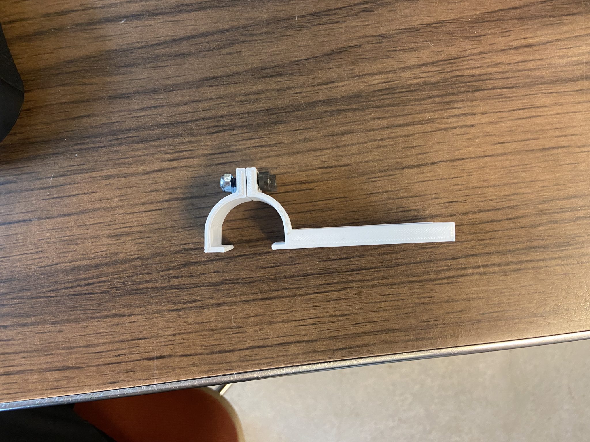
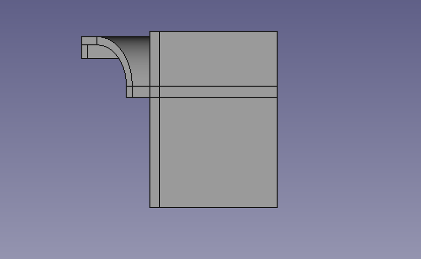
Restruder 3/24/2024 – 3/31/2024 Updates
This week I tested the design and made some adjustments to the design that will be put in the osf cite. In the original design the holes of the piece did not align with the circuit board. The board was printed off with 2.85 pla with the recommended settings for the printers. Also the amount of thickness of the board for the circuit board attachment could be reduced for more room for the bolts since there is not enough room for bolt and nuts between the printer and the design.
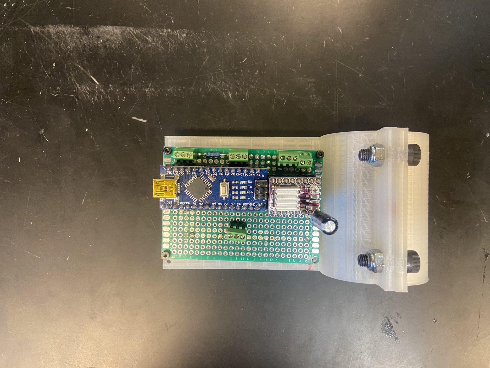
Original design
Original design on printer
When it is on the printer the bolt will need to be tightened for the part to stay still. However, in the future, the design might change since it is not easy to tighten the bolts at this moment. However once the bolts is tighten the design will stay in place. The newer design gives a slight distance between the part for the bolts to attached to. Also the holes of the part will be adjusted, however I made them to big so in the next upcoming week there will be more adjustments for the design. Putting holes to align a part is usually the hardest part of the design in my case.
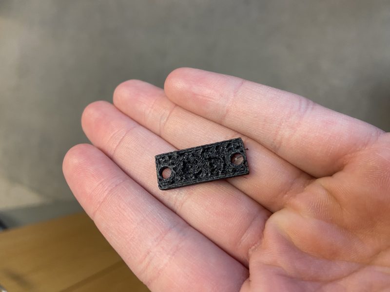
Current design of the part
Current design on 3d printer
There was an idea of making the part more easily attached in a marble spring attachment method. In which when the part is pinched it opens up and returns back to a close state when released. In which design will be worked on next week. Also I will be helping with finding the wiring scheme for the 3d printer in preparation of our circuit board being implemented with the design.
My Goals for the semester
- Attach our extruder assembly from last year to the extruder of the Luzbot Taz 6 (done)
- Print out of the current redesign of the sensor attachment (done)
- Design a way for a circuit board could be attached to the system (done)
- Test the sensor system to see if there are any issues (done)
- Find the wiring documentation for the 3d printer (in progress)
- Create a better design of the circuit board attachment (in progress)
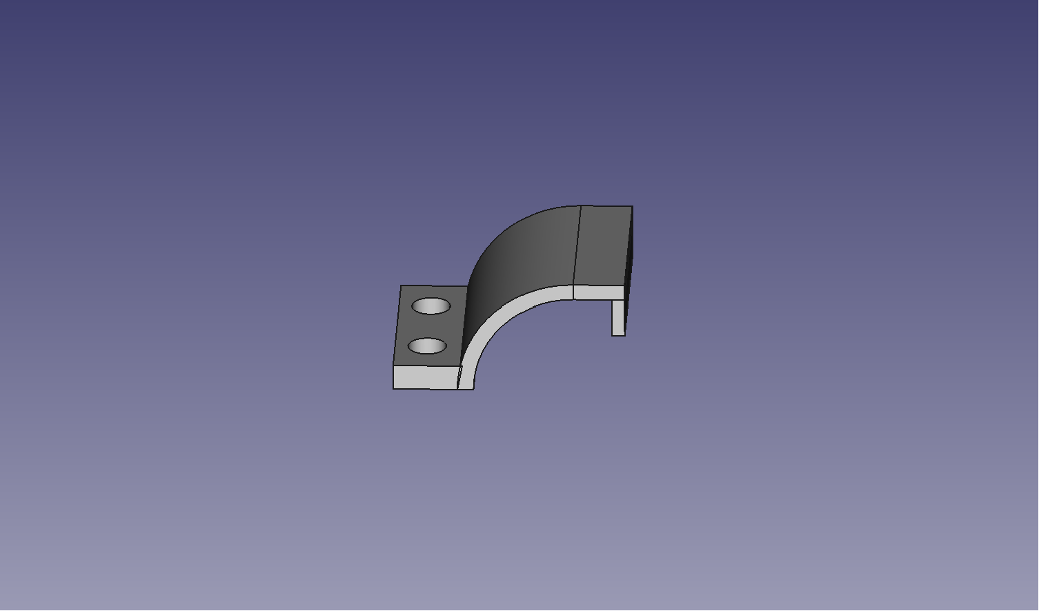
Restruder 3/31/2024 – 4/6/2024 Updates
This week I updated the design so it would fit the circuit board we are planning to use. I used 2.85mm PLA on the LuzBot Taz 6 to be able to print this part. In my design I kept the concept the same, however the pieces that the board with support would have to be longer.
Design of part
I choose to not put the holes for the circuit board since I always make the holes too far apart anyways. When printing this you can either add holes to the design for the circuit board you use or drill them out manually. I had to drill out and attach the circuit board to the piece.
cicuit board on piece
In this design the attachment turned in a snap on design which is really nice. This is only done when the bolts and nuts are tightened. The only downside is the circuit board does not attach very well and will have to be improved on later on. These files will be on our osf page. I also found some wiring documentation for the LuzBot Taz 6.
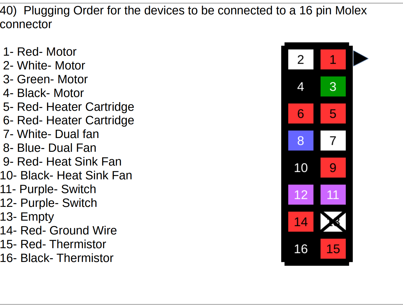
Circuit Documentation
Next week I will be helping with the implementation of the circuit board with the LuzBot Taz 6. This will include taking wires from the extruder system and powering our circuit system so our code could be tested.
My Goals for the semester
- Attach our extruder assembly from last year to the extruder of the Luzbot Taz 6 (done)
- Print out of the current redesign of the sensor attachment (done)
- Design a way for a circuit board could be attached to the system (done)
- Test the sensor system to see if there are any issues (done)
- Find the wiring documentation for the 3d printer (done)
- Create a better design of the circuit board attachment (in progress)
- Implement the circuit board with the system (in progress)
Restruder 4/6/2024 – 4/12/2024 Updates
This week I have done a couple of things. First I have redesigned the electronic holder to take up less space. This design is trying to not take up as much space on top of the 3d printer. While testing the design having the 3d printer head towards the upper bounds of z, the design got stuck and was difficult to remove. This new design is to take up minimal space so the 3d printer does not get stuck.
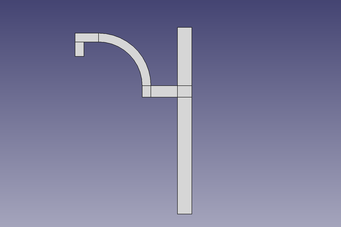
New design
In this I have printed this piece using 2.85mm pla and the stl file is on the osf cite under version 3.
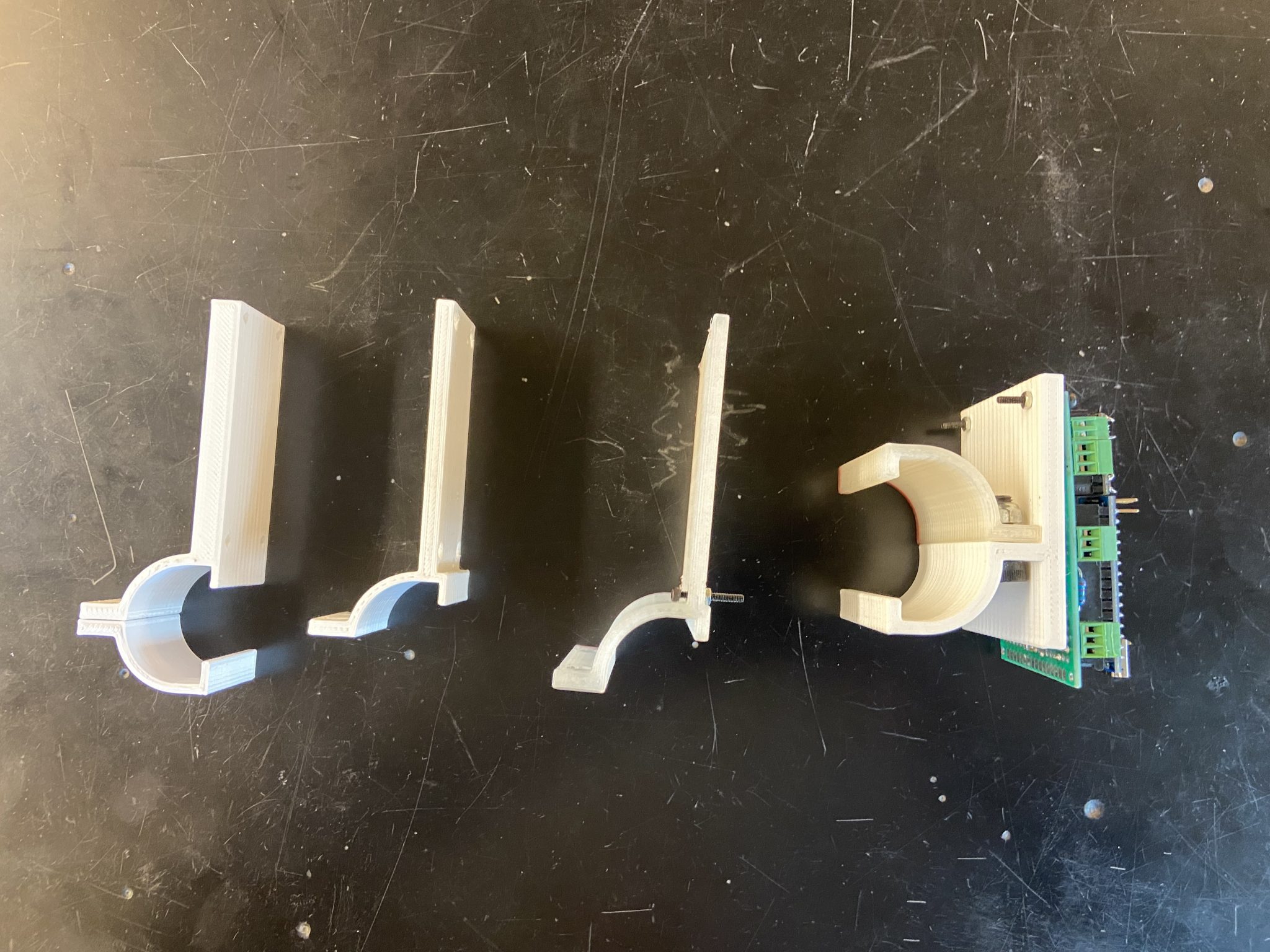
All designs starting form old to new
I am also setting up the integration of everything, getting it ready for testing that will happen in the near future. In this focusing on connecting all the wires and having wire management.
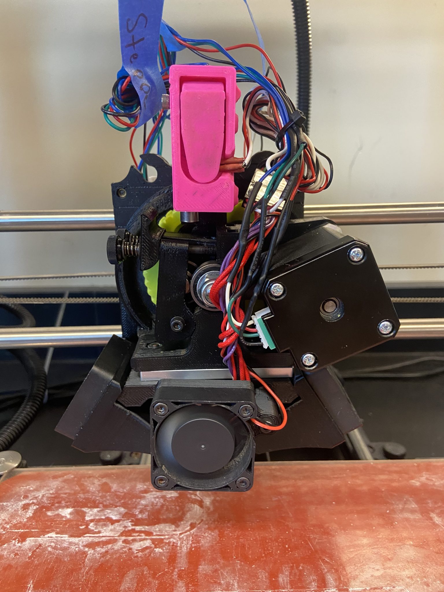

Extruder System
Next week I am finishing up the project with testing and writing the final report for this semester.
My Goals for the semester
- Attach our extruder assembly from last year to the extruder of the Luzbot Taz 6 (done)
- Print out of the current redesign of the sensor attachment (done)
- Design a way for a circuit board could be attached to the system (done)
- Test the sensor system to see if there are any issues (done)
- Find the wiring documentation for the 3d printer (done)
- Create a better design of the circuit board attachment (done)
- Implement the circuit board with the system (done)
Restruder 4/12/2024 – 4/19/2024 Updates
This week I mainly worked on the report and initial testings for the whole systems. In the case of the testing the motor was not moving and there were issues to be able to be found. The circuit board ended up needing to be redesigned to a more compact form. I was responsible for redesigning the circuit board holder for the 4th time.
new design
Our new circuit board is 3 cm by 7 cm and will have to be raised since there are now a lot of wires that can not be crushed. Currently this is being printed using 1.75 mm pla on the Ender 3. The stl is on our osf page. I also have been working heavily on the final report for the semester.
Concerns
I am a little concerned that our testing will have significant problems and will not have a lot of time to work on it. I am also worried that I will burn out at the last minute and have to focus on my upcoming exams.
Husky Clean Updates 8/26/2024 – 9/13/2024
Hello, this semester I am starting my final capstone project Husky Clean for the next two semesters. You might be wondering what Husky Clean is. Husky Clean is an autonomous heavy duty vacuum system that can handle messes in a lab/shop setting. Husky clean is planning to be able to clean general messes and objects like metal shavings and wood dust. However Husky Clean is not cleaning up hazardous material since that requires special cleaning instructions.
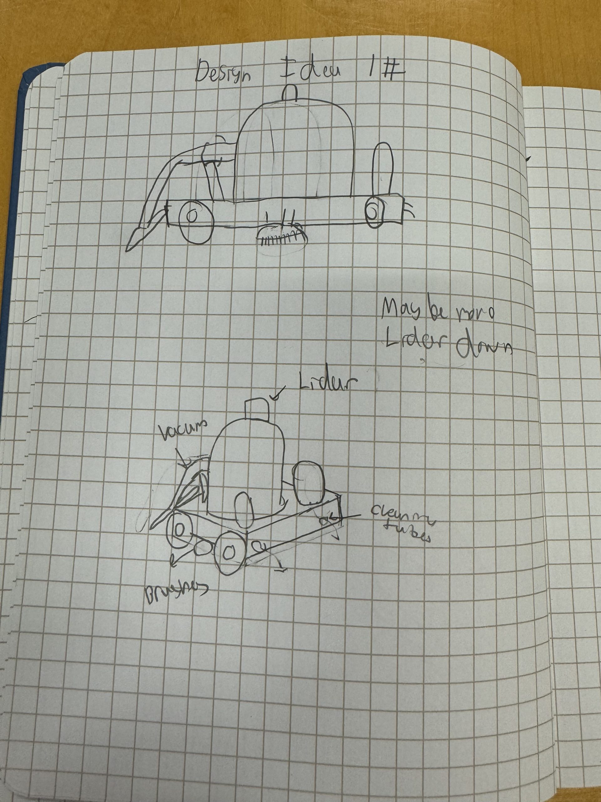
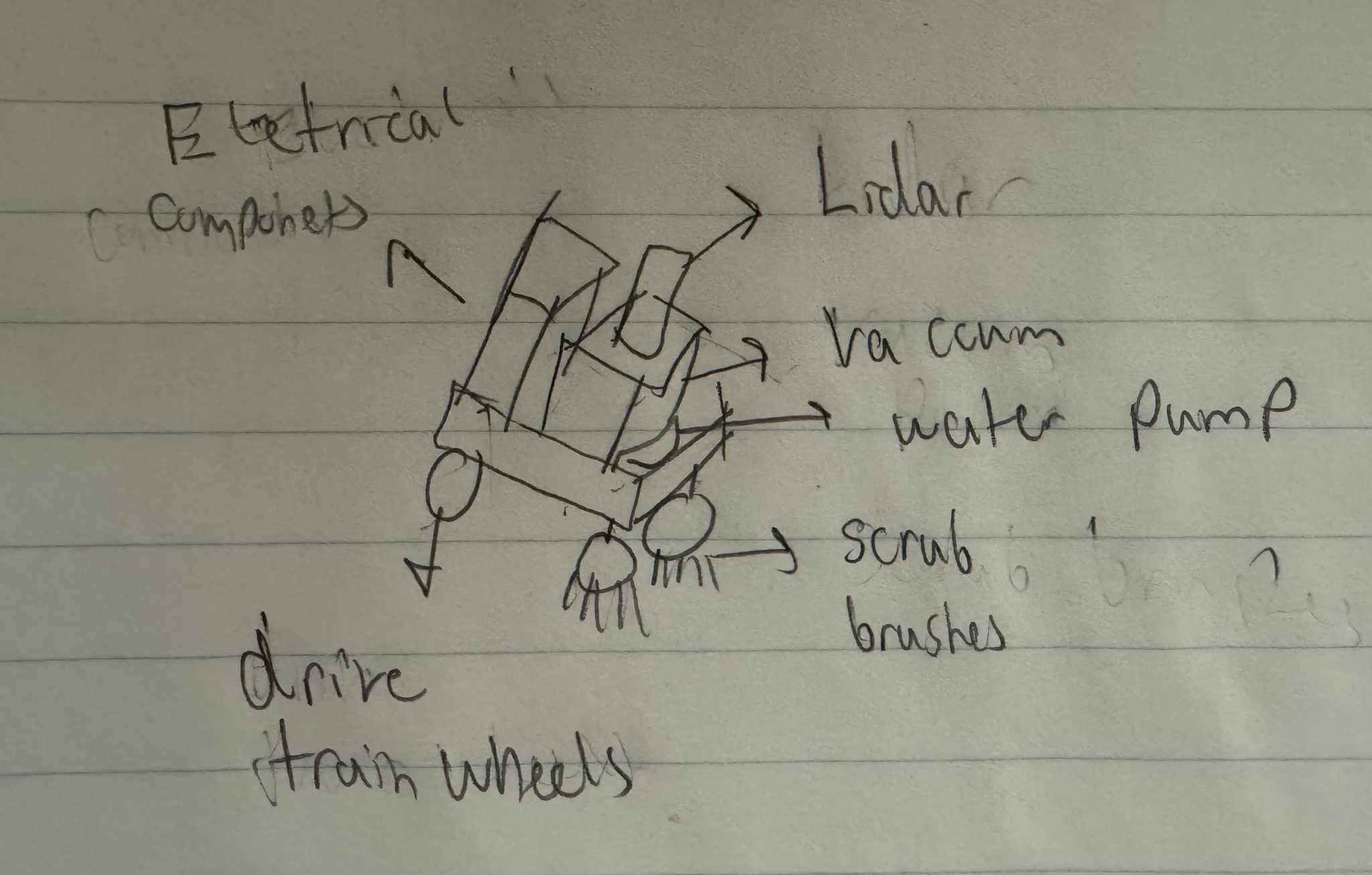
Design idea sketch
In which we plan by adapting a shop vacuum and incorporating other functions to the vacuum. There are a couple of subsystems to our design. Which are drivetrain, cleaning fluid dispenser, scrubbing brushes mechanism, and vision. Our goal is to have the robot be at a functional level so that we can start adding complex code. I will be mostly working on the scrubbing brushes mechanism subsystem and the code that follows the robot.
Scrubbing Brushes Mechanism Subsystem
For the scrub brush subsystem we had a couple of ideas on which brush we wanted to use for our subsystem. The three options we were debating is a circular brush, a coil brush, and a helical brush. In which we made a pugh chart comparing the three options to if we had no brush system as a base.
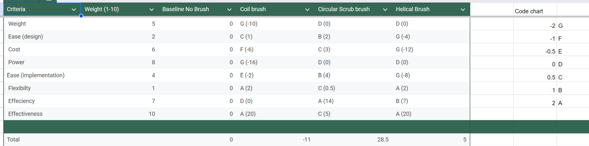
In which in our pugh chart the circular brushes were the most beneficial for our project. It would make sense since most of the industry follows using circular brushes. Now we are deciding on what size of brush we would want to use. We are currently planning on using two brushes nearby the robot center of mass.
Next Week Plans
- Decide size and order brushes
- Order a Raspberry pi 4b for the computer vision system
- Review the code that was used on a similar robot (GrowBot) from a previous semester
9/13/24-9/20/24 Huksy Clean Updates
This week I got the scrub brush order and the raspberry pi 4b order and patiently waited for them. I also went through the growbot old code to get a sense of what it does. I saw that it is using a remote and a radio transceiver to be able to control the robot through a remote. However I do not know much about how to interface with the code. Fortunately there is a lot of documentation that I can read so I am currently looking through that. It is kinda hard to design the placement of the motors and brushes when I do not know what the frame of the robot looks like. I am hopeful to start next week on that task.
Next Week Plans
- Start designing for brush motors
- Understand code
- Come up with a basic code structure for the Arduino
9/20/24 – 9/27/24 Husky Clean Updates
This week I worked on two major things. First the scrub brush has a prototype design and will be planning to print it out in the next couple of days. Second, I have a code draft for basic movements of the robot with a fixed speed. This is done through a FS-I6X RC receiver & FS-I6X 6-ch Controller. Which is only going to be temporary since we are planning to use a raspberry pi for our controller.
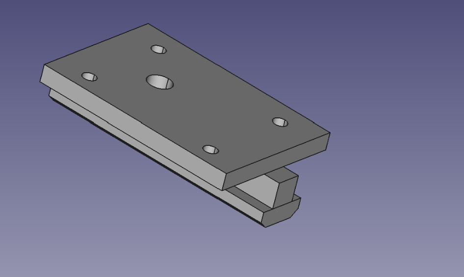
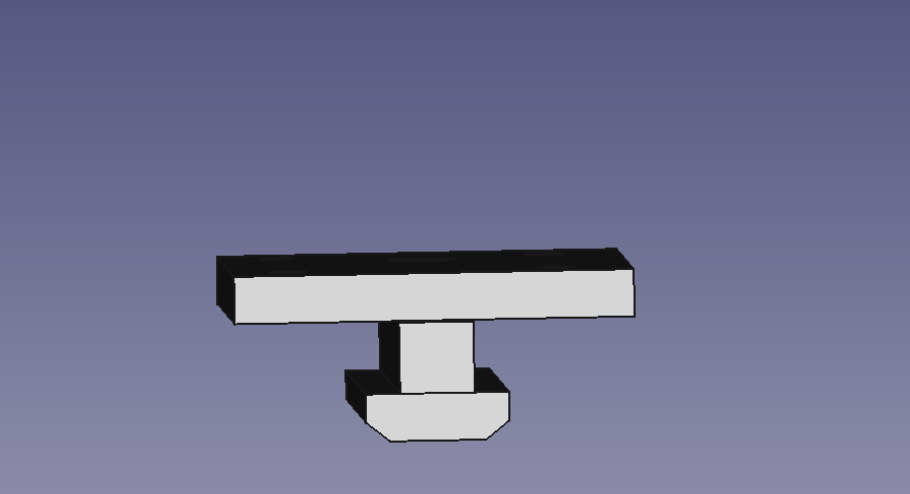
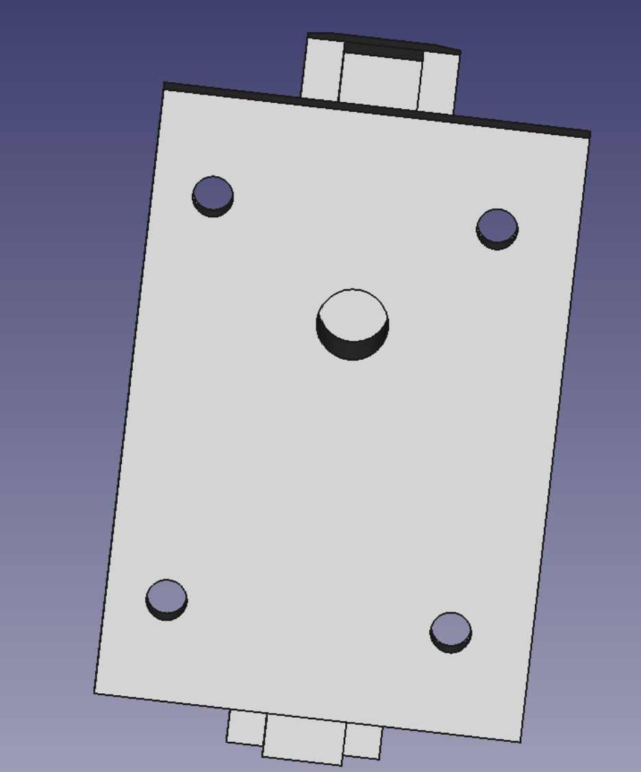
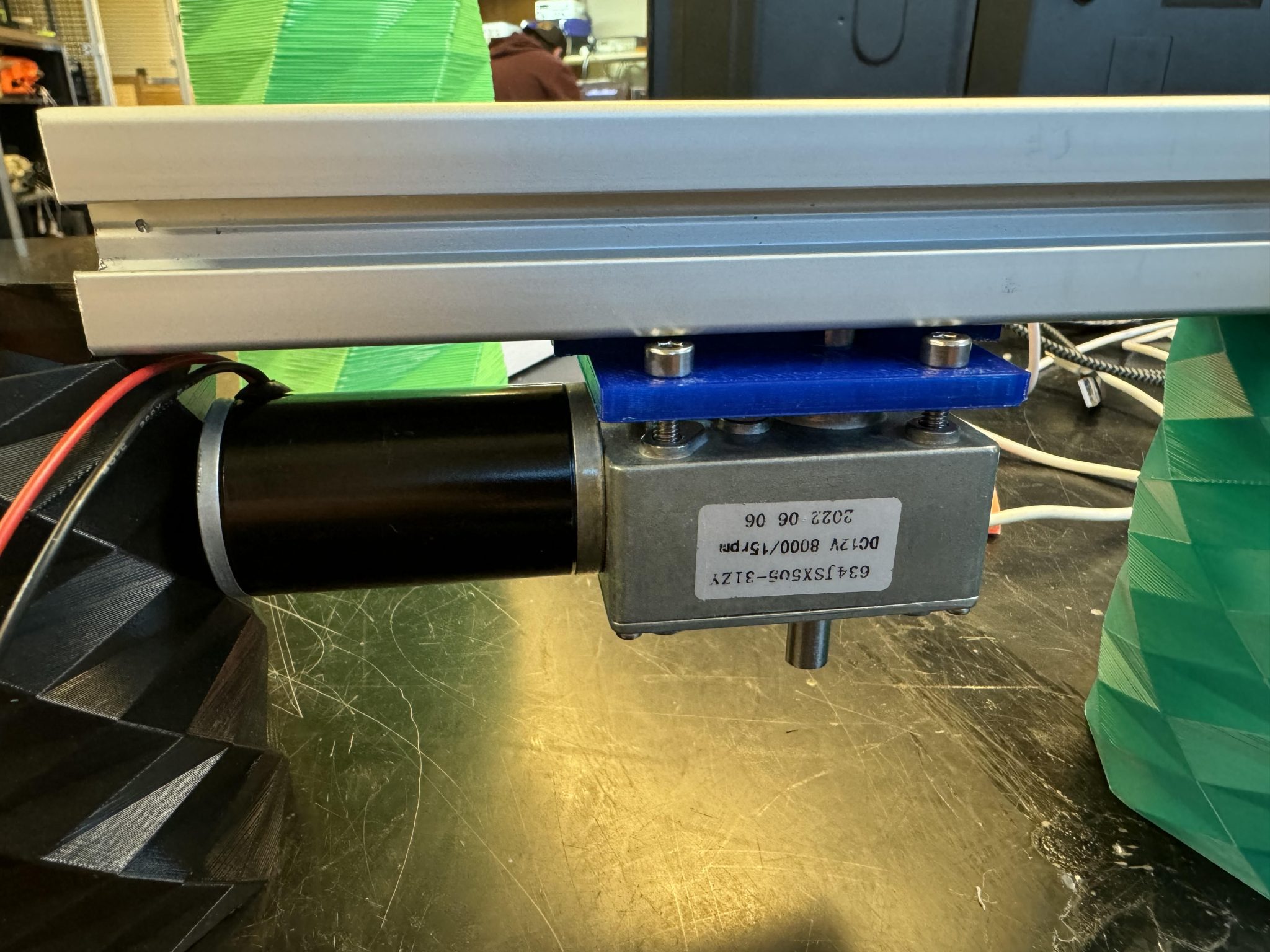
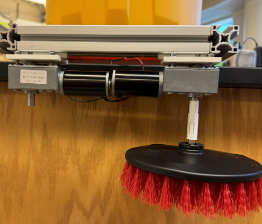
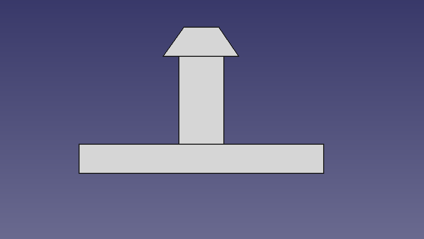
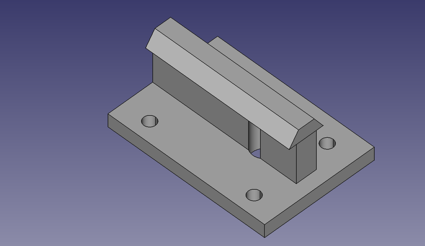
Scrub Brush Design
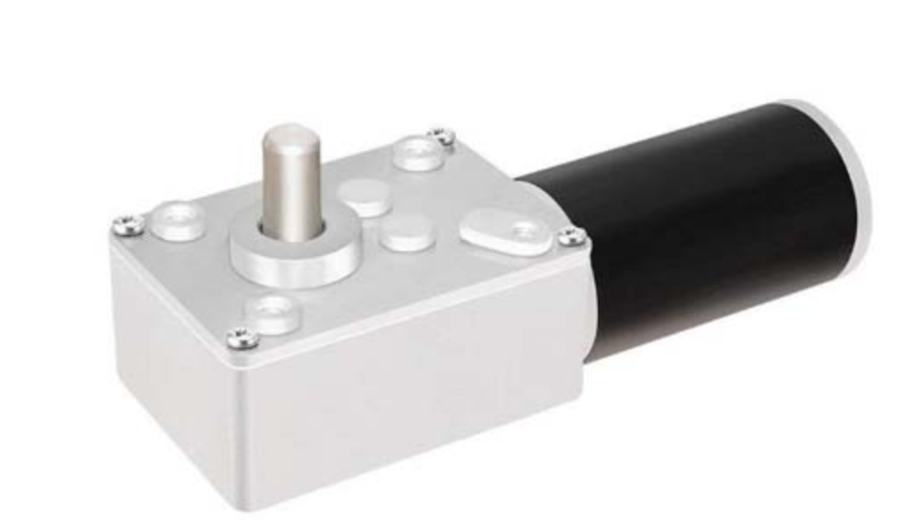
What we have prototype is a T slotted bar running across the center of mass of the robot in which we attach our scrub brush through an attachment. The attachment is meant to be slid into the T slotted bar for stability. To connect the motor and scrub brush together we designed a chuck. For the motors we are using a 12 DC volt motor which the part number is 634JSX505-31ZY. The concern that I have with this design is that I am not sure if the design can hold all the weight. We could not come up with a design with nice and pretty motor placements. So I hope for the best when this comes to testing.
Code
For the code I used a template to provide a simple code using a FS-I6X RC receiver & FS-I6X 6-ch Controller. This is used because we will need it for testing our design and electronics. We will be switching to either a python or C system using a Raspberry Pi and Ardunio. I want the final code to function similarly to the turtlebot robot. In which I want to use the same controllers however modify the structure for my own robot.
Code I wrote
/*
  Last updated: 9/26/24
  Husky Clean basic movement code
  Made to move forward, backward, left, and right at a fixed speed.
  Use the floowing code below as a base for this basic function.

  RC Remote Car
  fsi6x-RC-car-spin.ino
  Uses Flysky FS-I6X RC receiver & FS-I6X 6-ch Controller
  Uses TB6612FNG H-Bridge Motor Controller
  Drives two DC Motors

  Two Drive Modes - Normal and Spin
  Map channel 6 on controller to switch SWA for mode control

  Right stick controls direction in Normal mode (CH1 & CH2)
  VRA controls speed and direction in Spin mode (CH5)
  Left stick is acceleration in both modes (CH3)

  Channel functions by Ricardo Paiva - https://gist.github.com/werneckpaiva/

  DroneBot Workshop 2021
  https://dronebotworkshop.com
*/

// Include iBus Library
#include <IBusBM.h>

// Create iBus Object
IBusBM ibus;

// Channel Values

int rcCH1 = 0; // Left - Right
int rcCH2 = 0; // Forward - Reverse

// Motor A Control Connections
#define pwmA 3
#define in1A 5
#define in2A 4

// Motor B Control Connections
#define pwmB 9
#define in1B 7
#define in2B 8

// Motor Speed Values - Start at zero
int MotorSpeedA = 0;
int MotorSpeedB = 0;

// Motor Direction Values - 0 = backward, 1 = forward
int MotorDirA = 1;
int MotorDirB = 1;

// Control Motor A
void mControlA(int mspeed, int mdir) {

  // Determine direction
  if (mdir == 0) {
    // Motor backward
    digitalWrite(in1A, LOW);
    digitalWrite(in2A, HIGH);
  } else {
    // Motor forward
    digitalWrite(in1A, HIGH);
    digitalWrite(in2A, LOW);
  }

  // Control motor
  analogWrite(pwmA, mspeed);

}

// Control Motor B
void mControlB(int mspeed, int mdir) {

  // Determine direction
  if (mdir == 0) {
    // Motor backward
    digitalWrite(in1B, LOW);
    digitalWrite(in2B, HIGH);
  } else {
    // Motor forward
    digitalWrite(in1B, HIGH);
    digitalWrite(in2B, LOW);
  }

  // Control motor
  analogWrite(pwmB, mspeed);

}

// Read the number of a given channel and convert to the range provided.
// If the channel is off, return the default value
int readChannel(byte channelInput, int minLimit, int maxLimit, int defaultValue) {
  uint16_t ch = ibus.readChannel(channelInput);
  if (ch < 100) return defaultValue;
  return map(ch, 1000, 2000, minLimit, maxLimit);
}

void setup()

{

  // Start serial monitor for debugging
  Serial.begin(115200);

  // Attach iBus object to serial port
  ibus.begin(Serial1);

  // Set all the motor control pins to outputs

  pinMode(pwmA, OUTPUT);
  pinMode(pwmB, OUTPUT);
  pinMode(in1A, OUTPUT);
  pinMode(in2A, OUTPUT);
  pinMode(in1B, OUTPUT);
  pinMode(in2B, OUTPUT);

  delay(2000);

}

void loop() {

  // Get RC channel values
  rcCH1 = readChannel(0, -100, 100, 0);
  rcCH2 = readChannel(1, -100, 100, 0);

  // Print values to serial monitor for debugging
  Serial.print("Ch1 = ");
  Serial.print(rcCH1);

  Serial.print(" Ch2 = ");
  Serial.print(rcCH2);


  // Forward right joystick is up
  if (rcCH2 >= 10){
      MotorDirA = 0;
      MotorDirB = 0;
      } //Backwards right joystick is down
  else if(rcCH2 <= 10){
      MotorDirA = 1;
      MotorDirB = 1;
      }// Right right joystick is to the right
  else if(rcCH1 >= 10){
      MotorDirA = 0;
      MotorDirB = 1;
      }
  else if(rcCH1 <= 10){
      MotorDirA = 1;
      MotorDirB = 0;
      }


  MotorSpeedA = 20;
  MotorSpeedB = 20;
  // Ensure that speeds are between 0 and 255
  MotorSpeedA = constrain(MotorSpeedA, 0, 255);
  MotorSpeedB = constrain(MotorSpeedB, 0, 255);

  //Drive Motors
  mControlA(MotorSpeedA, MotorDirA);
  mControlB(MotorSpeedB, MotorDirB);

  // Print speed values to serial monitor for debugging
  Serial.print("Motor A Speed = ");
  Serial.print(MotorSpeedA);
  Serial.print(" | Motor B Speed = ");
  Serial.println(MotorSpeedB);

  // Slight delay
  delay(50);

}
Next week goals
- Print out scrub brush attachments
- Prepare and go to our Critical Design Review
- Debug code (if necessary)
- Start preparing for the raspberry pi
9/27/24 – 10/7/24 Husky Clean Updates
This week I focused on our critical design review. Which is a big presentation about our major updates throughout the semester. I also went through and started testing and redesigning the motor bracket for the scrub brushes.
Bracket attached to the motor
I am also trying to get an updated timeline since there are issues showing up with the whole project. The vacuum size was smaller than we expected. So our frame will have to be redesigned.
9/7/24 – 10/11/24 Husky Clean Updates
A lot of things happened this week. First things I continue my work on testing the scrub brush design. I printed out both of the chucks that are going to be attached to the motor and the scrub brush. A couple of issues popped up. First the frame of the machine does not have enough vertical room for the scrub brushes. Which is a huge concern that I have. Second, the chucks of this design are way too fragile and snap while testing them. We were planning to make the walls of the design thicker.
Scrub brush design
I also got a chance to update and test the drivetrain code for the robot to move. There were some wiring issues that were made while connecting to the motor controller. After that the code works as intended. There might be a chance that I have the direction backwards. Which is something that will come up with later testing.
/*
  Last updated: 10/10/24
  Husky Clean basic movement code
  Made to move forward, backward, left, and right at a fixed speed.
  Use the floowing code below as a base for this basic function.

  RC Remote Car
  fsi6x-RC-car-spin.ino
  Uses Flysky FS-I6X RC receiver & FS-I6X 6-ch Controller
  Uses TB6612FNG H-Bridge Motor Controller
  Drives two DC Motors

  Two Drive Modes - Normal and Spin
  Map channel 6 on controller to switch SWA for mode control

  Right stick controls direction in Normal mode (CH1 & CH2)
  VRA controls speed and direction in Spin mode (CH5)
  Left stick is acceleration in both modes (CH3)

  Channel functions by Ricardo Paiva - https://gist.github.com/werneckpaiva/

  DroneBot Workshop 2021
  https://dronebotworkshop.com
*/

// Include iBus Library
#include <IBusBM.h>

// Create iBus Object
IBusBM ibus;

// Channel Values
int rcCH1 = 0; // Left - Right (right)
int rcCH2 = 0; // Forward - Reverse (right)
//int rcCH5 = 0; // left dial
//int rcCH6 = 0; // right dial

// Scrub brush motor 1
//#define pwmS1
// Scrub brush motor 2
//#define pwmS2
// Fluid sytem drip
//#define pwmf

// Motor A Control Connections
#define pwmA 4
#define DirA 5

// Motor B Control Connections
#define pwmB 2
#define DirB 3

// Motor Speed Values - Start at zero
int MotorSpeedA = 0;
int MotorSpeedB = 0;
//int MotorScrub = 0;

// Motor Direction Values - 0 = backward, 1 = forward
int MotorDirA = 1;
int MotorDirB = 1;

// Control Motor A
void mControlA(int mspeed, int mdir) {

  // Determine direction
  if (mdir == 0) {
    // Motor backward
    digitalWrite(DirA, LOW);
  } else {
    // Motor forward
    digitalWrite(DirA, HIGH);
  }

  // Control motor
  analogWrite(pwmA, mspeed);

}

// Control Motor B
void mControlB(int mspeed, int mdir) {

  // Determine direction
  if (mdir == 0) {
    // Motor backward
    digitalWrite(DirB, LOW);
  } else {
    // Motor forward
    digitalWrite(DirB, HIGH);
  }

  // Control motor
  analogWrite(pwmB, mspeed);

}

//void scrubcontrols(int mspeed){
//  analogWrite(pwmS1, mspeed)
//  analogWrite(pwmS2, mspeed)
//}

//void fluidControl(int mspeed){
//  analogWrite(pwmf, mspeed)
//}

// Read the number of a given channel and convert to the range provided.
// If the channel is off, return the default value
int readChannel(byte channelInput, int minLimit, int maxLimit, int defaultValue) {
  uint16_t ch = ibus.readChannel(channelInput);
  if (ch < 100) return defaultValue;
  return map(ch, 1000, 2000, minLimit, maxLimit);
}

void setup()

{

  // Start serial monitor for debugging
  Serial.begin(115200);

  // Attach iBus object to serial port
  ibus.begin(Serial1);

  // Set all the motor control pins to outputs

  pinMode(pwmA, OUTPUT);
  pinMode(pwmB, OUTPUT);
  pinMode(DirA, OUTPUT);
  pinMode(DirB, OUTPUT);

  delay(2000);

}

void loop() {

  // Get RC channel values
  rcCH1 = readChannel(0, -100, 100, 0);
  rcCH2 = readChannel(1, -100, 100, 0);

  // Print values to serial monitor for debugging
  Serial.print("Ch1 = ");
  Serial.print(rcCH1);

  Serial.print(" Ch2 = ");
  Serial.print(rcCH2);


  // Forward right joystick is up
  if (rcCH2 >= 20 && rcCH2 > 0){
      MotorDirA = 0;
      MotorDirB = 0;
      MotorSpeedA = 100;
      MotorSpeedB = 100;
      } //Backwards right joystick is down
  else if(rcCH2 <= 20 && rcCH2 < 0){
      MotorDirA = 1;
      MotorDirB = 1;
      MotorSpeedA = 100;
      MotorSpeedB = 100;
      }// Right right joystick is to the right
  else if(rcCH1 >= 20 && rcCH1 > 0){
      MotorDirA = 0;
      MotorDirB = 1;
      MotorSpeedA = 100;
      MotorSpeedB = 100;
      }
  else if(rcCH1 <= 20 && rcCH1 < 0){
      MotorDirA = 1;
      MotorDirB = 0;
      MotorSpeedA = 100;
      MotorSpeedB = 100;
      }
   else{
    MotorSpeedA = 0;
    MotorSpeedB = 0;
   }
 // looking for any dial movement for scrub brushes
 // if (rcCH5 > 20){
 //    MotorScrub = 20;
  //}
// looking for any dial movement for fuild system
 // if (rcCH6 > 20){
 //   MotorFluid = 20;
  //}

  // Ensure that speeds are between 0 and 255
  MotorSpeedA = constrain(MotorSpeedA, 0, 255);
  MotorSpeedB = constrain(MotorSpeedB, 0, 255);
  //MotorScrub = constrain(MotorScrub, 0, 255);
  //MotorFluid = constrain(MotorFluid, 0, 255);

  //Drive Motors
  mControlA(MotorSpeedA, MotorDirA);
  mControlB(MotorSpeedB, MotorDirB);
  //scrubcontrols(MotorScrub);
  //fluidControl(MotorFluid);

  // Print speed values to serial monitor for debugging
  Serial.print("Motor A Speed = ");
  Serial.print(MotorSpeedA);
  Serial.print(" | Motor B Speed = ");
  Serial.println(MotorSpeedB);

  // Slight delay
  delay(50);

}
Video of the motor moving using a RC controller
Next Week Plans
- Update scrub brush design
- Update code to improve more features
- Start working with the Raspberry Pi
10/11/24 – 10/25/24 Husky Clean Updates
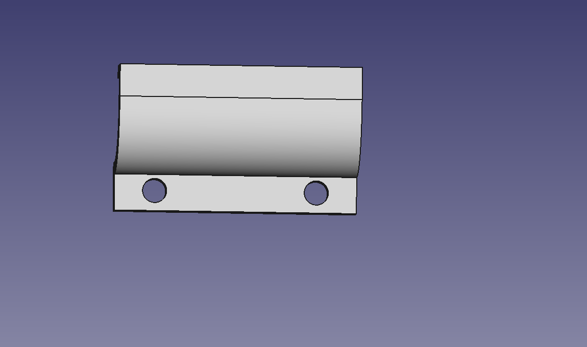
A lot has been going these past couple of weeks. First I went through some testing of the robot and there was some issue with the robot. It was determined later on that the motor controller that was being used had some issues with it. We suspected that the motor controller broke during testing at some point. We have ordered a new motor controller and hope that it fixes the problem. I also redesigned the motor bracket to be able to fit on to the updated frame. Which is a little bit smaller than the original one.
New Motor Bracket (Side View)
New Motor Bracket (Isometric View)
This bracket holds the same design as before other than the part that attaches to the frame. Planning on printing them this week and being able to test them.
Raspberry pi
There are a couple of things that are being started. First, I wanted to use a serial communication system to communicate between the arduino and the raspberry pi. So I am planning on using this tutorial as a base for the final code for the arduino. In which the arduino is being planned to be used for the controls for the robot. I was planning on using a PID controller to be able to handle some of the fine tuning of the robot movement. In which i want to set up to have both the raspberry pi and the arduino to communicate between each other.
Next Week Plans
- Finished a serial communication system
- Test the robot yet again
- A first draft of the final code for the arduino
- Figuring out lidar wiring
10/25/24 – 11/1/24 Husky Clean Updates
This week a lot of things are happening for the code side of things. I was able to have most of the first draft of my final code set up for the arduino. Except for a PID or PI controller for the drive motor. I was also able to get an array of data to send to the Arduino from the raspberry pi using UART communication.
Final draft 1 of Arduinio code
// This is the final code between the Ardunio and the Raspberry pi
// The purpose of this is getting the motor speeds and controls commands from the Raspberry Pi
// Then this code will take these values run it through a PID controller and passes that information back to the Raspberry Pi

//*************************************************************************************
// Pin Definitions
//*************************************************************************************

//Fluid system
#define DirF 8

// Motor A
#define pwmA 4
#define DirA 5
// Motor B
#define pwmB 2
#define DirB 3
// Scrub Brush Motor 1
#define pwmS1 6
// Scrub Brush Motor 2
#define pwmS2 7

//***********************************************************************************************
// Defining initail Motor Speed and Direction
//*******************************************************************************************************

int MotorSpeedA = 0;
int MotorSpeedB = 0;
int MotorScrub = 0;
// Motor Direction values 0 = backwards, and 1 = forward
int MotorDirA = 1;
int MotorDirB = 1;
int FluidDir = 1;

// Seperate functions for differnt functions controls
void DriveMotors( int MotorSpeedA, int MotorDirA, int MotorSpeedB, int MotorDirB){
// set a PID controller to the motor speeds

}

void SrubMotors( int MotorScrub){
  // Write speed to the scrub brushes
  analogWrite(pwmS1, MotorScrub);
  analogWrite(pwmS2, MotorScrub);
}

void FluidControl(int mdir){
  // setting a bit to 1 or 0 based on if it is on

  if(mdir ==1){
    digitalWrite(DirF, HIGH);
  } else {
    digitalWrite(DirF, LOW);
  }
}

void setup() {
// put your setup code here, to run once:
// Set the serial
Serial.begin(115200);

// Make sure that the board is connected to the arduino
while(!Serial){
}
Serial.println("Serial is working");
}

void loop() {
  // put your main code here, to run repeatedly:

 if (Serial.available() > 0){
   String Motor_Speed = Serial.readStringUntil('\n');

   int Speed[10]; // size of data numbers
   // the data will go by (motorA speed, motorA direction, motorB speed, motorB direction, srub brush 1, fluid dir)
   int index = 0;

   int lastComma = -1;
   for (int i = 0; i < Motor_Speed.length(); i++){
       if(Motor_Speed[i] == ',' || i == Motor_Speed.length() -1){
         // End of number string
          String numStr = Motor_Speed.substring(lastComma + 1, i + (i == Motor_Speed.length() - 1 ? 1 : 0));
           Speed[index++] = numStr.toInt();
           lastComma = i;
       }
   }
    Serial.println("Received Array");
    for(int i = 0; i < index; i++){
      Serial.println(Speed[i]);
    }

  DriveMotors(Speed[0], Speed[1], Speed[2], Speed[3]);
  SrubMotors(Speed[4]);
  FluidControl(Speed[5]);
 }

}
Raspberry pi script for UART commucation
import serial
import time

# Initialize serial communication
ser = serial.Serial('/dev/ttyACM0', 9600, timeout=1)
ser.reset_input_buffer()

def send_array(numbers):
    # Convert the list to a comma-separated string
    data_str = ','.join(map(str, numbers))
    # Send the encoded byte data over serial
    ser.write(data_str.encode('utf-8'))
    ser.write(b'\n')  # Newline to signal end of data

if __name__ == '__main__':
    # Example array to send
    array_to_send = [10, 20, 30, 40, 50]
    while True:
        send_array(array_to_send)
        time.sleep(1)  # Wait 1 second before sending again
Next Week Plans
- Start skeleton code for the raspberry pi
- Assembled scrub brushes to frame
- Be able to test our code for no autonomous features
1/6/25 – 1/18/25 Husky Clean Updates
During our first couple weeks of OHSE there has been a major issue. The Raspberry Pi 4b ended up breaking for some unknown reason. The board ended up getting fried so the display or boot process does not work anymore. We will have to find an alternative to the Raspberry Pi 4b and find the cause of this issue.
Other than the issues we have been mainly setting up what we have to do for our semester and the goal we have with this project. In which our project will be concluding this semester so we have to have a working product by the end of the semester. Which will be really changeling since of the time constraint.
What the project might look like
Plans for the Semester
- Figure out how to get a new raspberry pi 4b since it has broke
- Trouble wiring for any problems with the raspberry pi
- Set up Lidar communication between the raspberry pi and lidar
- Write code for dynamic obstacle avoidance using the lidar as our vision
- Add important life improvement changes for the raspberry pi
- Test our code for any bugs
1/18/25 – 1/26/25 Husky Clean Updates
During this week we did a lot with our lidar. I was tasked with getting the communication of the lidar so that we can receive data. Unfortunately we are going through a major issue in which nothing is recognizing the lidar. Even the closed source software that is meant to see S1ck lidar products. So most of the time I spent my time troubleshooting what had happened. We have also reached out to one of our sponsors for this project to see if they have any insight.
Next Week Plans
- Trouble shoot why the lidar has no communication with any of our system
- Start adding improvements to the Raspberry Pi so the Pi is in a safer working condition
1/18/25 – 1/26/25 Husky Clean Updates
This week our Lidar is still not working which halts most of my progress. We contacted S1CK Lidar (our sponsors) and we had a meeting going over troubleshooting. They suspected either the cable or the Lidar to actually not work. To test out the cable theory, another one is being sent to us to see if that is the issue. However a service script has been written on the raspberry pi so the ROS launch file can run based off of start up. I have not started the service yet to test it for a while. I have not gotten the time to set a test procedure with the conditions we are in.
Next Week Plans
- Wait for cable to come in and trouble shoot the lidar
- Start in creating test procedures for when the robot is moving
1/27/25 – 2/14/25 Husky Clean Updates
This week we got a new cable from S1ck and now we can see the lidar data. However when trying to get the data onto some file we have issues. We are currently troubleshooting that and troubleshooting how to integrate the lidar with our raspberry pi. Our pi is giving a ip 6 address to our Lidar but to be able to work with it. We would need an ip 4 address to be able to work with any of the repositories that we have.
Next Week Plans
- Trouble shoot Lidar
- Work on raspbeery pi some more
2/14/25 – 2/21/25 Husky Clean Updates
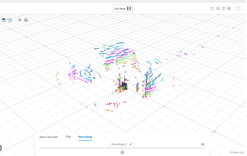
A lot of things were happening this week. We have gotten a little more knowledge on how the lidar worked and gotten some success with some of the Lidar data information. Which leads us to more questions. We have finally gotten access to get the data from the Lidar. The raw data that we have gotten is completely in hexadecimal which is not the expected output that I have worked with before. I am completely unfamiliar with how to translate that into a decimal point cloud. Which I and my team will need to ask around and figure out how to work with this data.
Some minor progress is happening with the integration with the Lidar and the raspberry pi. The network settings have changed so that the Raspberry Pi has a static ip 4 address. With the lidar the address of the Raspberry Pi has to be mostly the same. For example if the Lidar ip address is 192.167.27.1 then the raspberry pi address would have to be 192.167.27.2. With the change of setting the static ip of the Raspberry Pi, the Raspberry Pi is able to use the ping command to communicate with the ip 4 address of the lidar. However the problem is now that the Sopas software necessary to be able to look into and work with the Lidar is not working with the lidar. Which is the part that is necessary to have our robot operate.
Setting a Manual Ip 4 Address on a Raspberry Pi
You will want to edit the /etc/netplan/50-cloud-init.yaml file to be able to set up. You will want to be able to keep the wifi information the same but change the ethernet setting to this.
network:
  version: 2
  ethernets:
    eth0:
      addresses:
        - 192.168.1.1/24  # Static IP for the Raspberry Pi
      dhcp4: no
      optional: true
/etc/netplan/50-cloud-init.yaml code
Concerns
With everything coming to a close I am getting very nervous to be able to get this project set up and running. Even with the amount of work and progress, I am still very confused on how to work with this Lidar. This is an extremely challenging project that has many struggles and concerns. It is becoming really hard to be able to keep up with my classes and my project.
Next Week Plans
- Trouble shoot Lidar
- Work on raspbeery pi some more
3/3/25 – 3/9/25 Husky Clean Updates
Some things happened last week in the OHSE enterprise. In the software that we are using to be able to give data to our raspberry pi to be able to work with it with obstacle avoidance. In the sick_mutliscan.launch file that we are using, the point cloud data is being published to a /multiScan/scan_fullframe. However we are unfamiliar with what the data is acutely publishing. We get a huge matrix that has a bunch of points but we are unfamiliar on where the data of the Lidar start. In my experience when I get this type of data it was a 2d matrix where the first point started at 0 degrees of the lidar and went counter clockwise. This is extremely important to be able to write our dynamic obstacle code and be able to fine tune the code. We wanted to be able to visulate the data to make sure that we are calling the right topic but we are struggling to do that. We are currently trying to use rviz to visualize the data. In which our problem is being able to assign a world frame that our launch file wants.
Next Week Plans
- Work with the Lidar data
3/9/25 – 3/15/25 Husky Clean Updates
This week we spent time writing all the code for our autonomous function and functionality between the arduino and raspberry pi. In which we just have a simple obstacle avoidance since we do not have enough time to be able to write a pathfinding program. We are trying to add a function to have the program get killed based on a remote button. This will make it more smooth for testing and general use. Right now we are troubleshooting since we are running into so many errors. We are trying to get the robot autonomously moving by the end of next week.
Next Week Plans
- Troubleshooting
3/15/25 – 3/23/25 Husky Clean Updates
This week a lot has happened. While E-stop testing our Raspberry Pi sd card got corrupted. Since we were working really hard to make our project working by the end of this week, we did not have any backups of the boot files. We kinda lost everything and had to start from square one. In which after a long week, I was able to get back to the position we were and add some obstacle avoidance to our robot. In which this is a short description of what our current algorithm does.
Our pathfinding algorithm is designed to help a robot navigate its environment using the LiDAR. The code listens and provides information about distances to obstacles in all directions. The code divides the robot’s surroundings into four directions: North, East, South, and West. It then checks each sector to see how far the nearest obstacle is. If there is enough space for the robot to move, it’s considered a valid direction for the robot. The script then picks the direction with the most open space and decides that’s the best direction to go. If no sector has enough space, the robot stays in place. Once the best direction is chosen, the script sends out a simple message indicating which way the robot should move. This message is an array of numbers, where a “1” marks the chosen direction and “0” marks the others. The script keeps running, constantly checking the sensor data and updating the robot’s movement direction as needed. It’s a simple but effective way to help the robot avoid obstacles and find open paths.
However the current protocol can be improved. As testing yields us with multiple errors and mistakes. Also in this we did not add scrub brush and pump functionally. In which we will start doing that next week.
Next Week Plans
- Improving our system
- Added scrub brush and pump to our automnomous code
3/23/25 – 3/29/25 Husky Clean Updates
This week we have updated our obstacle avoidance code to be able to work with our FLysky controller. This is so our digital enable and safe shutdown that could be used in the program. I have also updated the code to be able to run both the scrub brushes and the pump in both the arduino and the autonomous code.
This week was mostly testing and getting ready for our checkoff next week. We are also fine tuning our code to avoid obstacles better. We have mostly been testing dry since the vacuum is not ready to be used. It still needs to be fixed at this point. We were planning on running wet over this weekend and creating a consistent area to run in. We had talks of adding a path planning to our autonomous area but we think there is not that much time this semester to be able to do it.
Next Week Plans
- Wet testing our system
- Starting to write the report and posting code
3/29/25 – 4/5/25 Husky Clean Updates
This week not much has changed. We have been doing a bunch of testing and trying to optimize our system. In which our system acts accordingly with code. However this has a higher error rate and acts in unpredictable ways. I have mostly been getting the project ready for our final checkoff and starting to write documentation for our project. Since I have gotten sick over this week.
Next Week Plans
- Documentation
- Optimize System
4/5/25 – 4/13/25 Husky Clean Updates
This week I have put most of my effort in documentation of Husky Clean. Also working on a presentation for my senoir capstone project.
4/13/25 – 4/18/25 Husky Clean Updates
This week I am focusing on wrapping up for the semester. I finished up documentation for Husky Clean and all of the code has been updated. I am presenting what I have done over the course of this project. Now I am focusing on transitioning things to the newer members of the group.