9/22
This week the team visited the mine we will be working on (Mead Mine). While we were there, we were only able to walk around the outside. We were able to scout the location as well as start brainstorming different options for power generation. A few ideas were thrown around for cooling systems as well. I also began researching more deeply into power generation options. I reached out to the Mining students who are working on this project with us so we can get together and figure out how our teams will be working together. The team had also met to discuss different options for the project including how to implement a weather station to collect data and update our project specification form.
For next week, we plan on meeting with the Mining students, if possible. We also would like to have a decision made if we are utilizing a weather station or not. More discussions on power generation systems will take place too. We will be meeting with our advisor to check in too.
10/7
Our team was told the Mining students would not begin working on the project until next semester, since their team had not been assembled yet. After meeting with Dr. Oberloier to discuss that development, our team was back on track. Even though we aren’t sure exactly what electronics we will be using yet, I started researching different options for weatherproof case options. I also facilitated communication between our team and Dr. Manser, who will lead the Mining students in the Innovative Global Solutions (IGS) Enterprise. We are currently in discussion about the possibility of Dr. Manser procuring some equipment that would allow us to gather point data to map the cave. This data will allow us to get a better understanding of the environment we are working in. Overall, our team is making good progress, despite a few minor setbacks.
10/28
After the setbacks mentioned above, our team is still moving forward. Most recently, I have been conducting research into ways to measure the output of solar panels so we can test a few different locations around the mine. The location of the mine is very remote, so there are limited options. Being able to determine where the solar panels will be most efficient will be paramount to our success. We are anticipating limited power generation, so being able to maximize what we can gather is a high priority right now. We are looking to travel out to the Mead Mine within 2 weeks so we can set up some test solar panels so we can find the best location. We have also been in contact with Douglass Houghton Student Chapter of the National Society of Professional Surveyors to help us collect point cloud data of Mead Mine. These coming weeks should see a lot more tangible progress.
11/4
This week, we continued preparations to make a trip out to our location. We are scheduled to go on Thursday with more or less everyone involved in the project, which will be great. We will ideally be able to set up our testing solar panels to test the amount of solar power we can generate for any of our planned test areas. We will use this data to confirm the best location for the solar panels in the future. We plan on installing them now so we can get them up before the snow hits. We will also be able to get point cloud data of the cave to hopefully be able to run some thermodynamic calculations with the help of some colleagues since nobody on our team is familiar with thermal calculations. Specifically, I finalized research on what we will be using to house our electronic components and protect them from the harsh elements during the winter.
1/26/2024
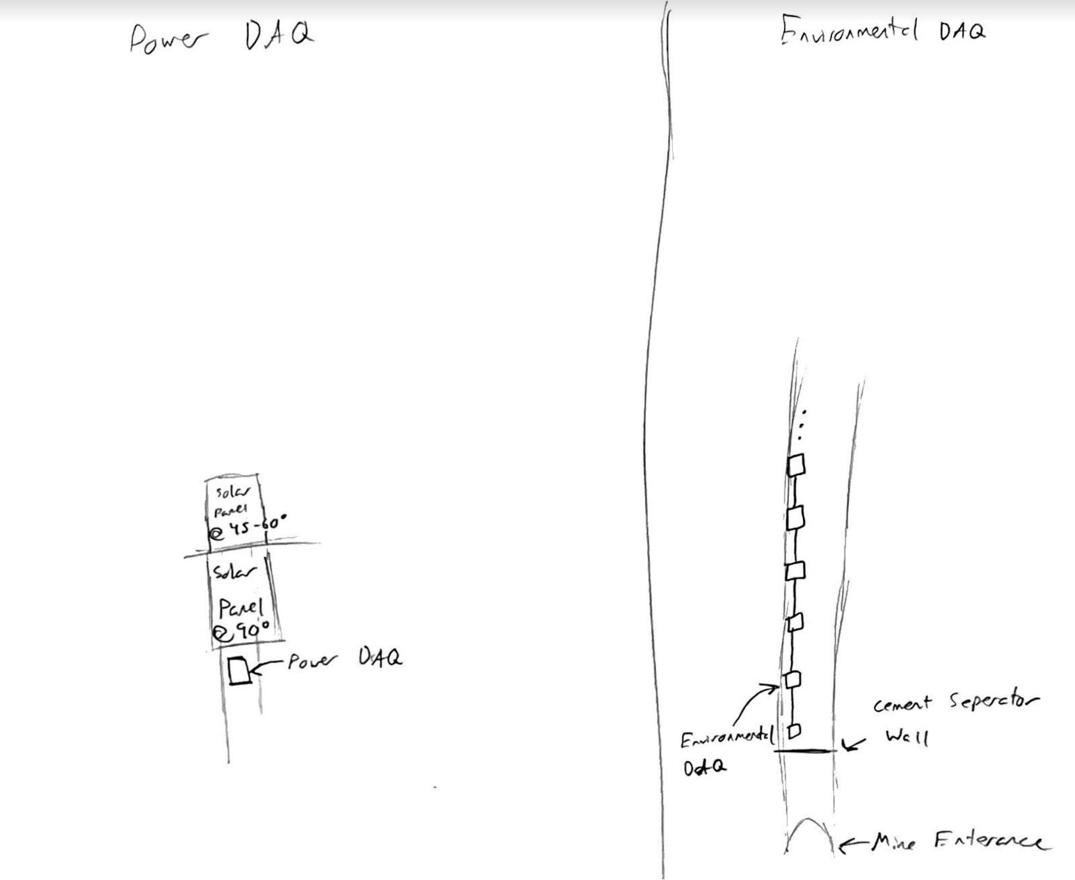
We left off before the holiday break by having almost completed our Power Data Acquisition System (Power DAQ). Now that we are back from break, we have confirmed our test solar panel stations are still standing, even after many feet of snowfall, and only a small amount of snow has accumulated on the panels. We were not certain our construction would stay standing, but hearing confirmation they were still standing was a big win. At this point, getting back out to Mead Mine is difficult; only being accessible by snowmobile. In the meantime, the team has continued work on completing the Power DAQ, and the design for the Environmental DAQ (the system that will be in the cave collecting temperature and humidity data) has been finalized. This week I began soldering all the parts together, with the hopes to finish it next week so we can begin testing. Seen below is a basic drawing of the plans for our final system. The Power DAQ will be used to confirm the best location for a solar panel array that will be installed at a later point. The Environmental DAQ, once tested and finalized, will be duplicated and placed throughout the mine to get multiple temperature readings.


2/2/2024
Last week I made progress on assembling the Environmental DAQ. I soldered multiple components together. This week the team decided to make a push to reach a deadline we had set at the beginning of the semester. Our goal was to have a working Power DAQ installed by the end of this week, and we are on track to complete that goal. After completing the prototype, and solving a few issues, the prototype collected data successfully. This week I put the Environmental DAQ on hold to help build two more Power DAQs that were higher quality than the prototype, so other members of the team could install them over the weekend, completing our first timeline goal. Next week is Winter Carnival at MTU, so realistically, I believe I will just be making progress on the Environmental DAQ. I hope to be able to complete it, but with Winter Carnival, I will be happy as long as progress is made. We still have some time before we want the Environmental DAQ ready to go, but ideally, it is done before we need it done so we can work out any bugs or issues.
2/10/2024
This past week was Winter Carnival at Michigan Tech, so progress was slowed a little bit this week with all the festivities. I made more progress on soldering the prototype Environmental DAQ. For this coming week, I hope to make more progress/finish the Environmental DAQSee below for a diagram and explanation of the Environmental DAQ.
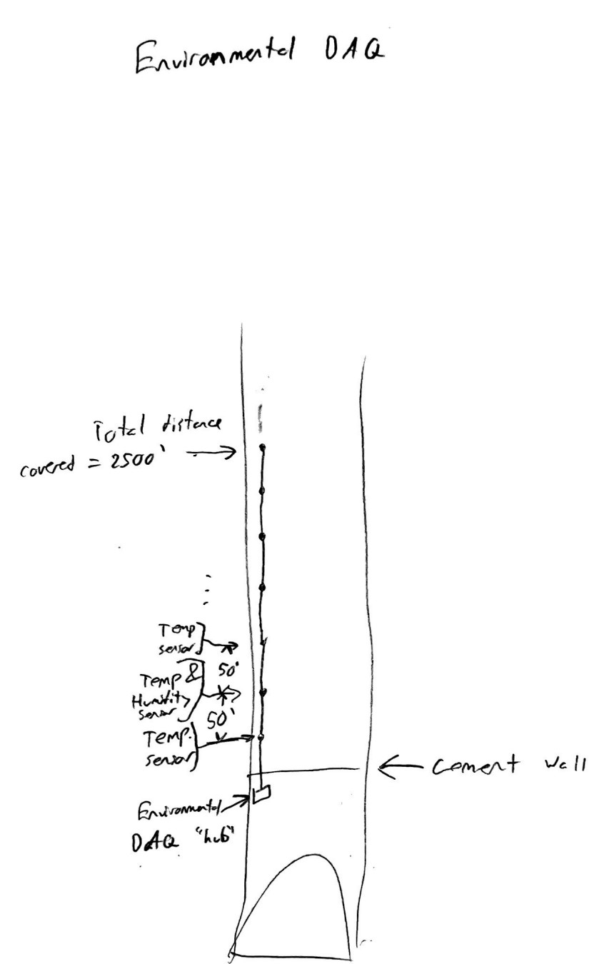
The above (rough) drawing shows the plan for the Environmental DAQ. There is a cement wall where we will be placing the “hub” that will allow for easy access for data collection; allowing for data collection without disturbing the bats. There will be, in total, 2,500 feet worth of wire and sensors. At each 50-foot mark, we will have a temperature sensor, and every other node will likely contain a humidity sensor as well. The length of the system will hopefully provide sufficient data to show temperatures at many different points along the path and give a good idea of where bats will likely want to move to, and help determine if the cooling system is working.
2/17/2024
Dr. Jared Wolfe, a professor working with our team, the DNR, and a few other groups had a meeting about our project this week. It was organized to make sure we were all on the same page and make sure everyone had what they needed to continue making good work on the project. In this meeting, we discussed our plans for the Environmental DAQ, and we were told that another group was going to be gathering the same information using a different method. We were then told to focus our efforts on the solar power generation and cooling system. This was different than what we had anticipated going into that meeting, but we have stopped working on the Environmental DAQ at their request and we will be switching our efforts to figuring out the cooling system in the meantime. We also had Thomas go out and install our Power DAQs, so those should be up and running now. Our Critical Design Review (CDR) is this week, so we are preparing for that. As for my work, I will be helping with the CDR slides and beginning work on figuring out what to do for the cooling system.
For the cooling system, we are working with a few different people who are helping us get some thermal calculations so we know exactly how much energy we will need to cool the space. We are planning on using the existing fan system to start, but more research will be conducted to find an alternative solution just in case the existing system will not suffice.
2/24/2024
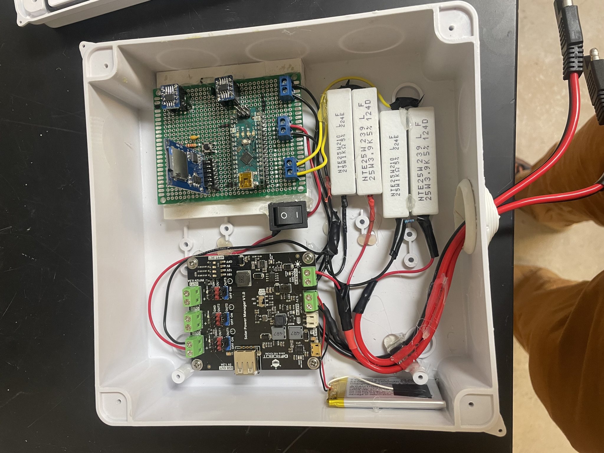
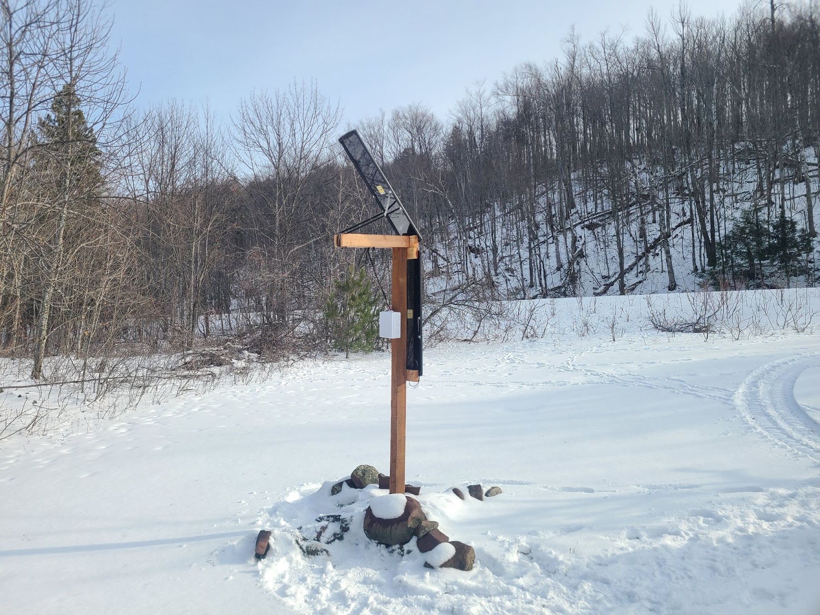
The first image below is a completed power DAQ and the second image shows the installed power DAQ. Thomas installed them on 2/14 and they are being used to collect data now. The components are glued down for a few different reasons. The first is to keep it organized and the second is to make sure the components aren’t just shifting around, especially since the whole box is mounted vertically, so when it was installed, the components would have fallen on top of each other.
For work this week, we decided to go ahead with a modified version of the Environmental DAQ. We figured it would still be a necessary part of the project since it would be needed in the controller process for the cooling system. Alex is working on updating the schematic. We are also very drastically reducing the size of the environmental DAQ system, which is still being discussed, but the plan is to have 4-5 nodes just to ensure the cooling system is providing cooling. As for my work, I will be completing the same environmental DAQ system I was building before since it will be pretty close to the one we will be using now, and it is almost done. This week is spring break, but the plan is for me to finish the prototype regardless.
3/9/2024
I finished assembling the Environmental DAQ, but we ran into issues getting it to work with our power supply. The problems seemed to be coming from the buck converter. After multiple failed attempts to solve the problem, we decided to change out a few components. Those will be ordered soon if they have not been already. Next week I will be problem-solving for the Environmental DAQ, and I will be helping get the updated PCBs ordered.
3/16/2024
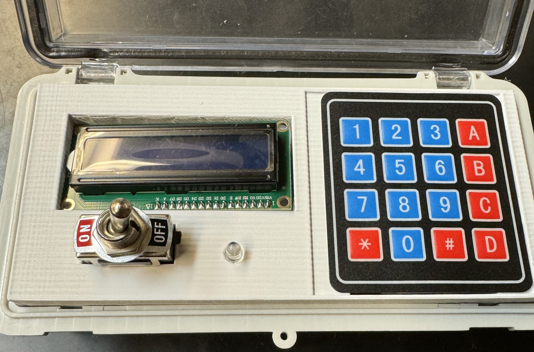
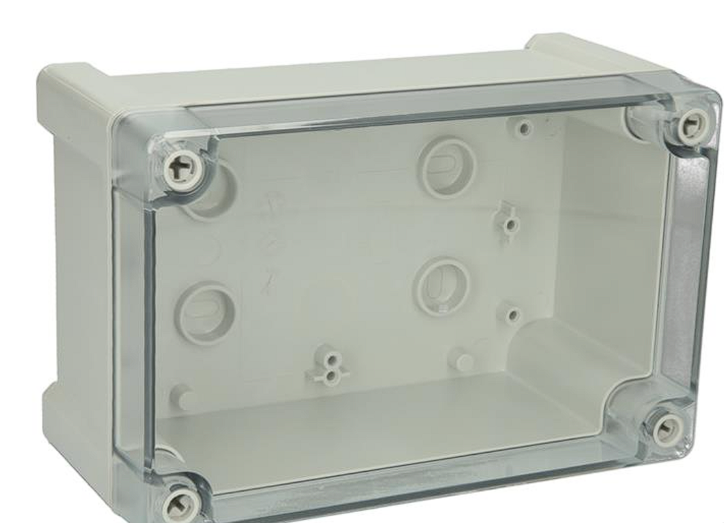
The updated prototype for the Environmental DAQ was completed, and Alex ordered some PCBs that we will use for final testing to make sure our orders can be completed correctly by ordering the DAQ using an online PCB manufacturer. This week, I started researching options for the UI for the system in the cave. The first choice that was made was choosing to buy a box compared to 3D printing a box for an LCD screen/controls. We decided to go this route because a 3D printed box would be harder to acquire if someone doesn’t have a 3D printer, and a 3D printed box would not be as waterproof/weatherproof compared to a commercial option. I am also looking into options for LCD screens that are more waterproof too, as a redundancy. We received a request to install a keypad so the system would be able to be set at a specific temperature, so that is another component I am looking into a container for. One option (shown below), is to just use the same type of box we used to contain the Power DAQ, but with a clear lid. There would need to be something worked out to get a keypad that would work, and not compromise the waterproofing of the container.
3/23/2024
This week I worked on the UI. I selected parts that will be used to make the UI, including a LCD, switch, a LED, and a keypad. The keypad will be used with the LCD screen to be able to show what temperature the system is at, and be able to change the desired temperature for the system. The LED will be used to signal that the system is running without issues. I also started designing an insert for a different clear lid box that was selected. This insert will just make the UI look much cleaner and make wire management easier to handle. The parts were ordered this week, and should be in by Monday I expect.
3/30/2024
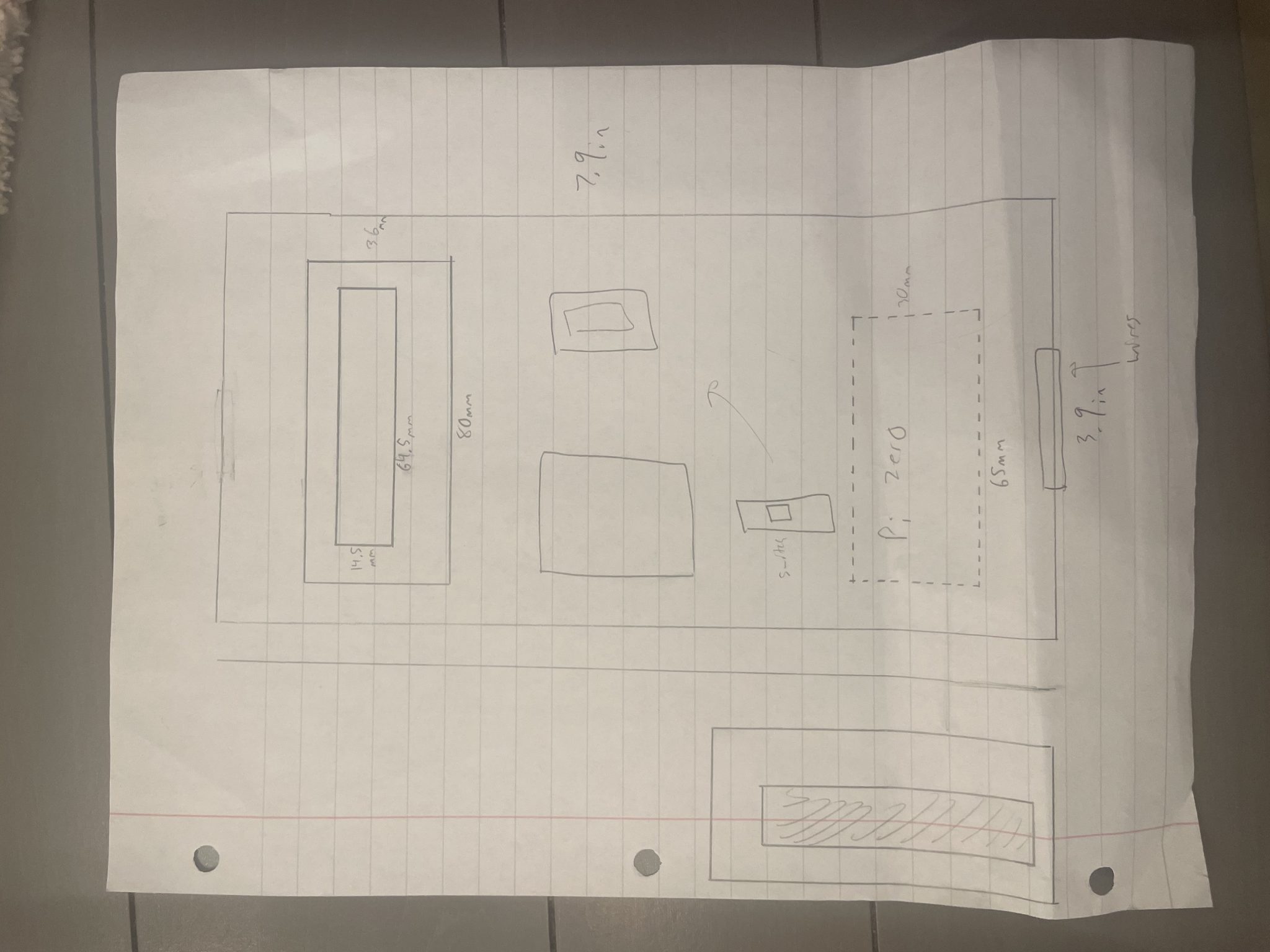
This week I made some progress on designing the UI and creating the insert to go in the box. The insert will allow for better wire management and an overall cleaner look. The drawing below is a rough sketch of what the inside of the box will look like. I left for a conference this week, so I was not able to make as much progress as I would’ve liked. I am returning late Tuesday night, and on Thursday afternoon I am leaving for another trip, so a concern of mine is getting everything done with enough time to troubleshoot and make adjustments as needed.
4/6/2024
This week I made progress on completing the 3D insert and schematic for the UI. The initial design for the insert will be completed today, and I hope to complete the schematic today as well. I have never made a schematic by myself before, so it has taken me some time to figure out what I am doing. I am anticipating it not being the best, but I hope it will at least be serviceable so my teammates do not need to redo it. For the insert, I had taken measurements of all the parts and the box we are using, everything seemed to fit a little better in person. Since I am out of town this weekend too, my teammates are printing the insert and wiring the UI together based on my schematic. The goal is to have a working UI by the end of this weekend.
4/13/2024
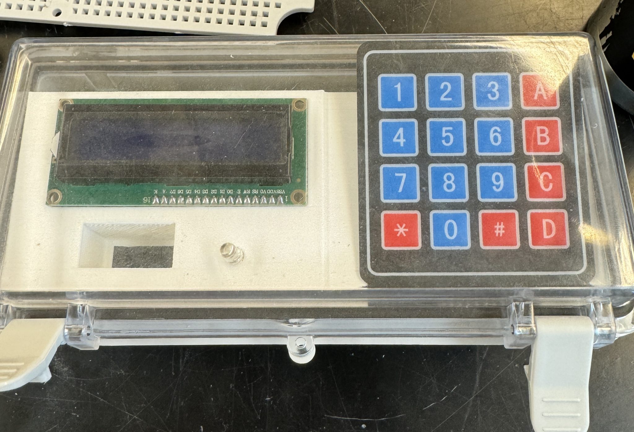
This week I finished the initial design for the 3D insert and schematic. I also gathered some initial code to implement the components (LCD, keypad, etc.) with the Raspberry Pi. I struggled to get access to put the code on the Pi, so I asked Thomas for help since he has much more experience at this than I do (I have no experience), he is working on getting the code at least on the Pi so we can edit it. I printed the 3D insert, and it worked very well for the first attempt. I went through 3 versions of it before printing, and the third version worked almost perfectly. I had to make some changes to a few of the measurements since almost all of the holes were a millimeter or two too big or too small, so the components didn’t fit how I liked. They are small changes, then I will have to re-print, and we will have to make sure it is strong enough to use the components with. I am worried about two spots in particular, underneath the keypad and where the switch is. The keypad itself is very light, but when the user pushes down on a button they will be putting more force behind it. In version 3 I added a support underneath, but the support does not touch the bottom of the container because we need that space for the Pi and other electrical components. For the switch, I am worried about the side-to-side forces when they flip the switch. The switch I chose requires quite a bit of force to use it. I think it might be ok since the side of the insert is up against the side of the container, and there should be enough strength with the fill percentage of the print to cover the other side. I am not 100% confident though, so I will have to give that some testing. One thought is to just print with a higher fill percentage, but I used 20% which is quite normal, and the print already took a decent amount of filament and took 8 hours to print. If my only option is to raise that percentage, I will, but I would rather keep the print time and the amount of filament roughly where they are. For next week I will be finishing the UI, including the re-printing and testing. On 4/16 we have Design Expo, so it needs to be done before then.
Below is a picture of how it looks as of now. The lid does not close all the way and they keypad also sticks up because of the way we have to bend the wires down to connect them to the Pi.
4/20/2024
This week I re-printed the insert due to the sizing issues. I have been fine-tuning the design to make sure everything is working properly. To start, I made the whole design shorter and slightly smaller so it fits under the lid. I also made the device cutouts the proper sizes. The only one that still needs work is the switch cutout. The switch fits in now, but it needs to be deeper so the switch doesn’t prevent the box from closing. I also redesigned the cutout for the switch because of the way the wires need to be connected to it. I was worried about the strength of the insert for using the switch and keypad, but all of the tests I have done have worked perfectly with no issues. While we have not tested the entire setup due to the code still being worked on, there should be plenty of space under the insert for everything we need.
This week I will print the final insert and finalize the UI overall. The box we used did not have pre-drilled holes for the wires to go in/out, so I will have to drill a hole and use the included gaskets we got with the box to ensure the wires can go in and out properly.