Week of April 14 – 20 2025
This week I did the peer review of one of the final report drafts. From here I reviewed the final report of Husky-Clean to make sure that the electrical part was done, and to check and see which sections still needed work. I also did the peer evaluations of the other members of Husky-Clean. Finally, I met with Nick and Wesley to make sure that the relay connection between the vacuum switch and the Arduino was still working. Once we determined that the connection was working we scheduled a meeting with Dr. Shane to have him review it as one of functional requirements. We gained some points back for it. As this was week 14 and the last week of classes, and there is nothing else to do but finish the report, that is my only plan for next week.
Week of April 7 – 13 2025
This week I met with Nick to add a relay that was connected to the switch of the vacuum. We wanted to get the vacuum connected to the rest of the electrical components.
After this I met with Nick and Wesley to practice our Capstone presentation. We met and made some adjustments after running through it once. Then I went to the Capstone presentation. We also used our Capstone presentation for the GM check in. I finally wrapped up my lab manager task of filament storage. As I am done with the electrical section and the Capstone portion of the project I do not have many tasks left. My plan for next week are to work on the report, and go to the meeting with Dr. Shane to get some of our functional requirement points back.
Week of March 31 – April 6 2025
This week I met with the other members of Husky-Clean to run tests on the autonomous system before functional requirement check-off on Tuesday. Well there I secured a servo to the vacuum part that will turn the robot on and off using the electrical system we designed through the Arduino MEGA.
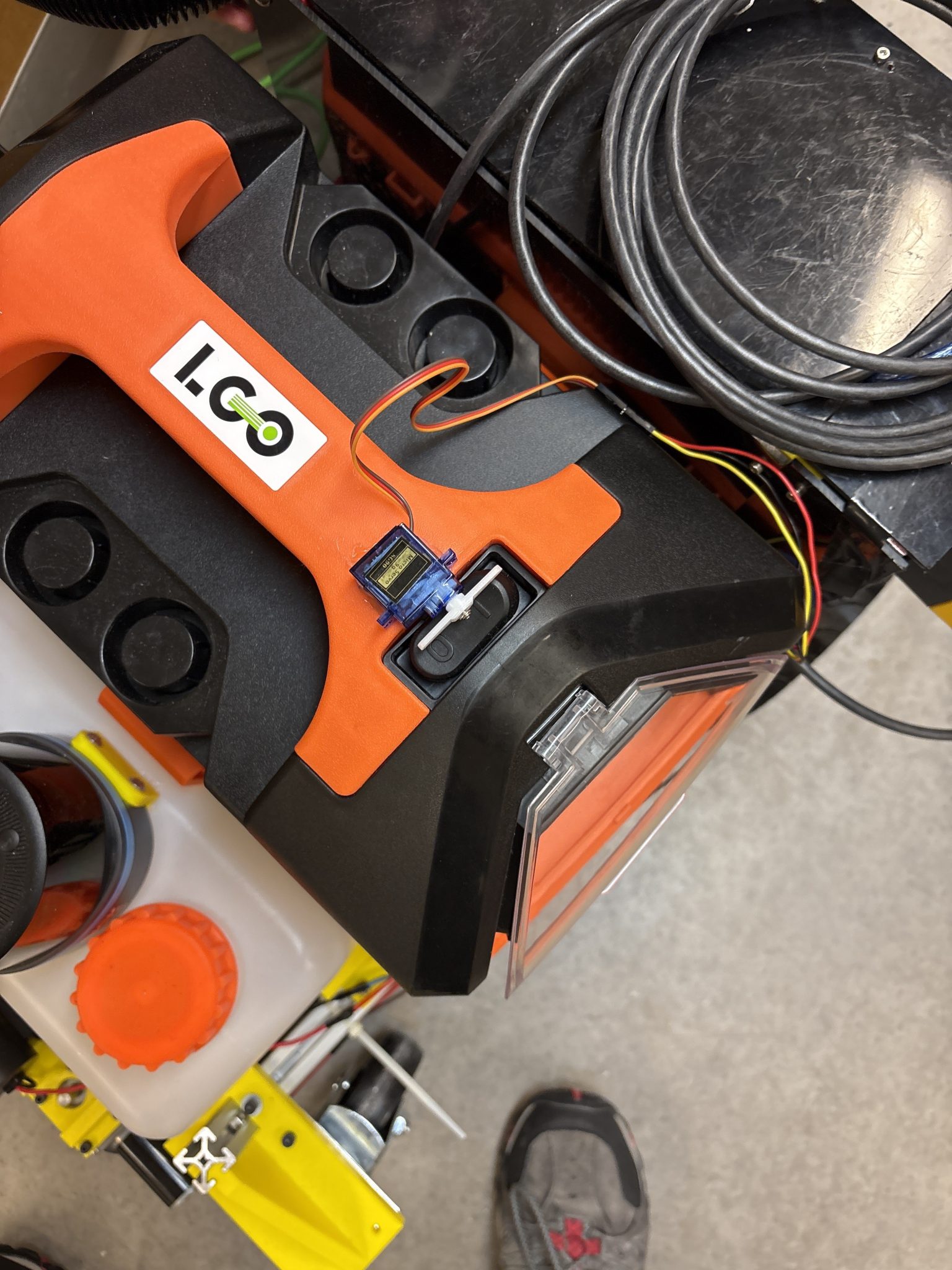
However, despite securing the servo it was unable to work without someone holding the servo down. After this I went to the functional check-off meeting with Dr. Shane. I helped move obstacles into the path of the robot. I also explained how we organized the wiring by drilling holes in the electrical boards, shortened wires, and added connectors to make disconnecting easier. After the functional requirement check-off, Georgia released the Capstone presentation schedule. Due to this I met with Nick and Wesley to work on our parts of the presentation as we will be presenting on April 10th. Next week my plan is to work with Nick to replace the servo with a relay to turn the vacuum on and off, finish my part of the Capstone presentation, do a practice presentation with Wesley and Nick, work on the GM progress update, and do the Capstone presentation.
Week of March 24 – 30 2025
This week I met with the other members of the group. We met to discuss the functional requirements and determine when we wanted to meet to test before our check-off. I also started the Capstone slideshow that most of the group will need. I started work on my section by adding a number of slides going over the electrical process that we did. While I have not worked on it again, the plan is to finish it during this upcoming week. I also started the GM slide show and went to the GM progress report meeting on Friday. Earlier in the week Seth disconnected the scrub brush motors, so I reconnected them. I flipped the wires on one of the scrubs and now they run in the opposite direction. I also helped Seth put the castor wheel mounts, and the scrub and pump mount on the robot.
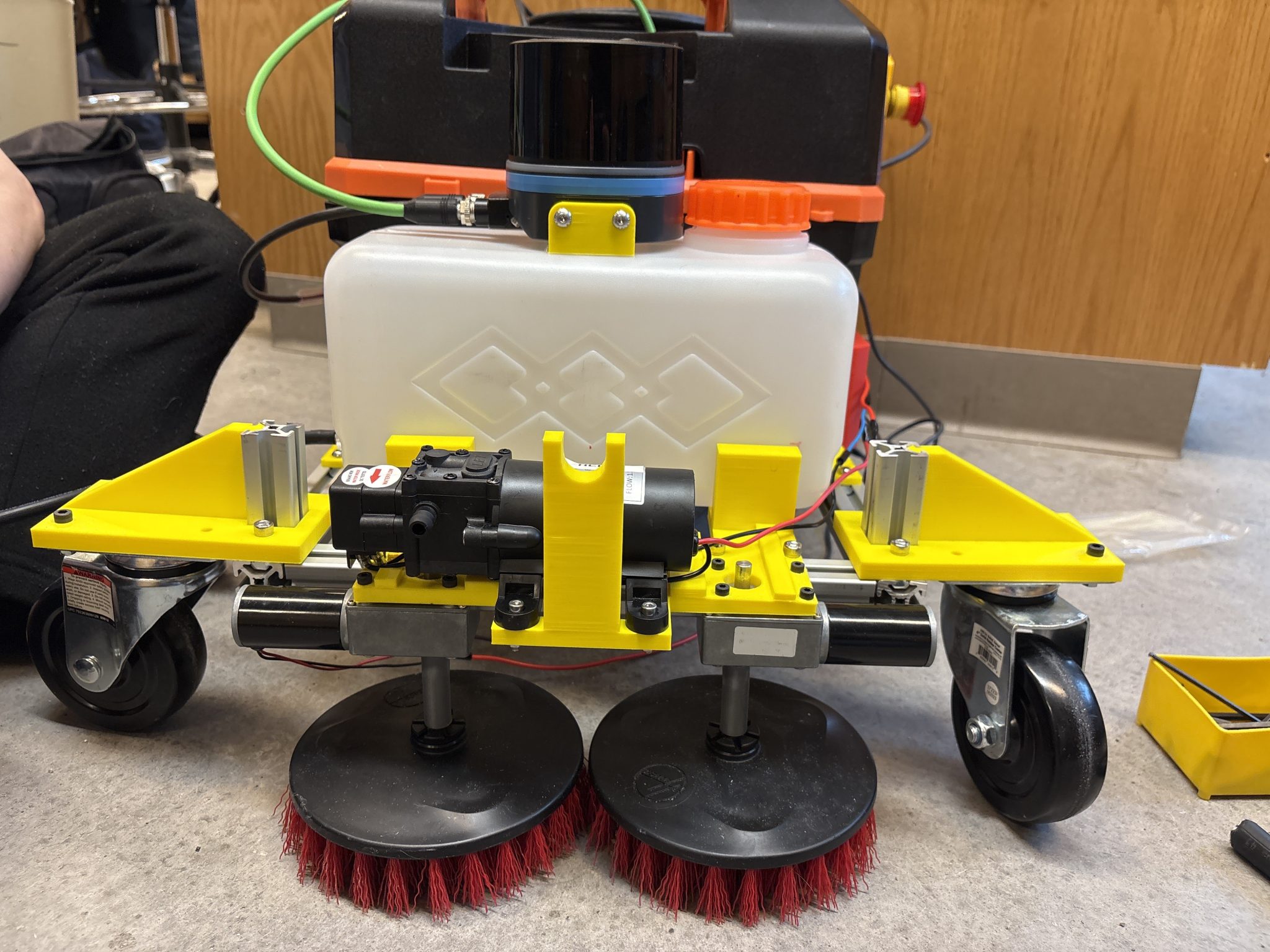
I also went on Sunday to help run some tests on the scrubs and vacuum part of the robot before check-off. Next week the plan is to make sure we are ready for check-off, and to work on the Capstone presentation.
Week of March 17 – 23 2025
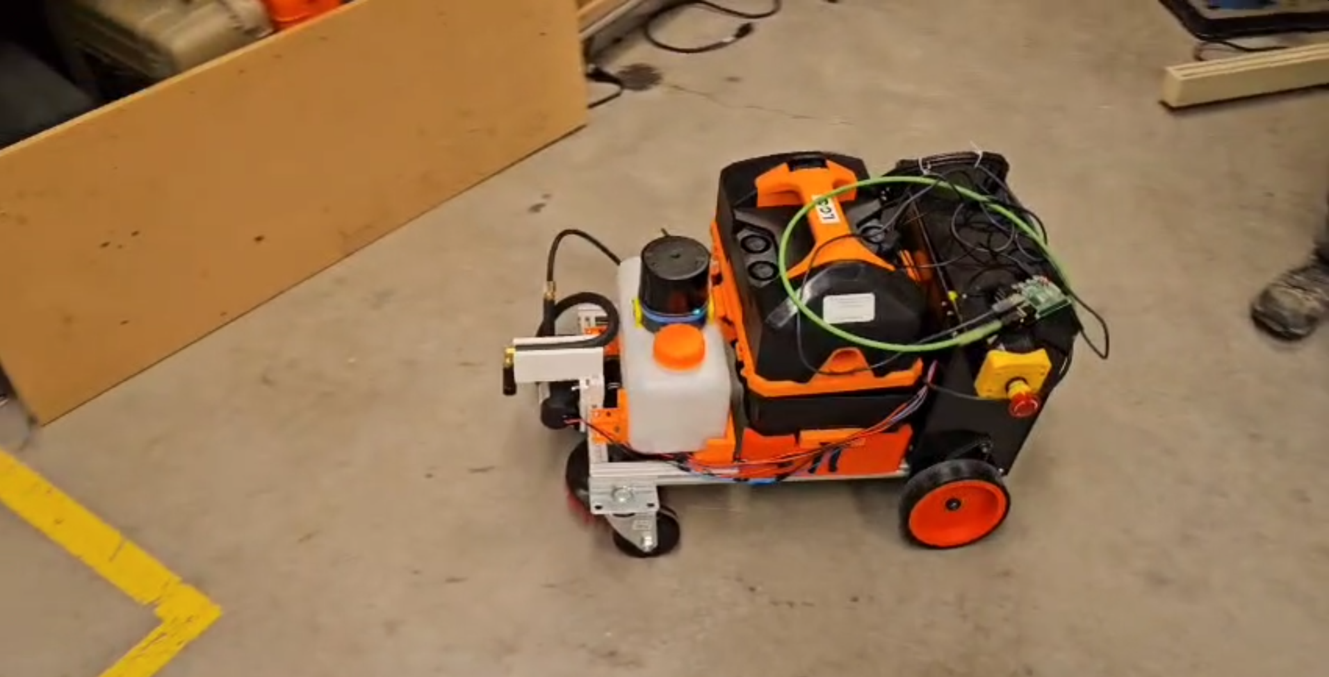
This week the focus was to get a video and short report made for the SICK LiDAR challenge. I met up with the other members of Husky-Clean on Thursday and Friday to do this. On Thursday, Lindsey, Jacob and Wesley met to work on the code for the autonomous drive. I was there to review the script we had written, look over the short report, and just in case any of the electrical or mechanical parts broke. I felt that the script and and short report were good, and when talking with the group came to the decision to meet with Nick on Friday to record the script for the video. Nick and I met on Friday in the morning and recorded the script. Nick had the application to edit the video and started work on that. Seth and Wesley later arrived to continue work on the autonomous code. They eventually got it working and I recorded the robot driving autonomously as well as the scrub brushes and pump working which Nick added to our video submission to SICK.
This upcoming week the plan is to work on the GM presentation we have and making sure that we are hitting all of the functional requirements as we approach the check-off day.
Week of March 10 – 16 2025
This week, with the completion of the water resistant box and the new electrical boards done, I wanted to focus on finishing the wiring of the robot. To do this I worked on soldering the connections between the relays, and the pump and scrubs. I did this by cutting some wire to connect the components and then soldering them together. After this I used electrical tape to cover the connections.
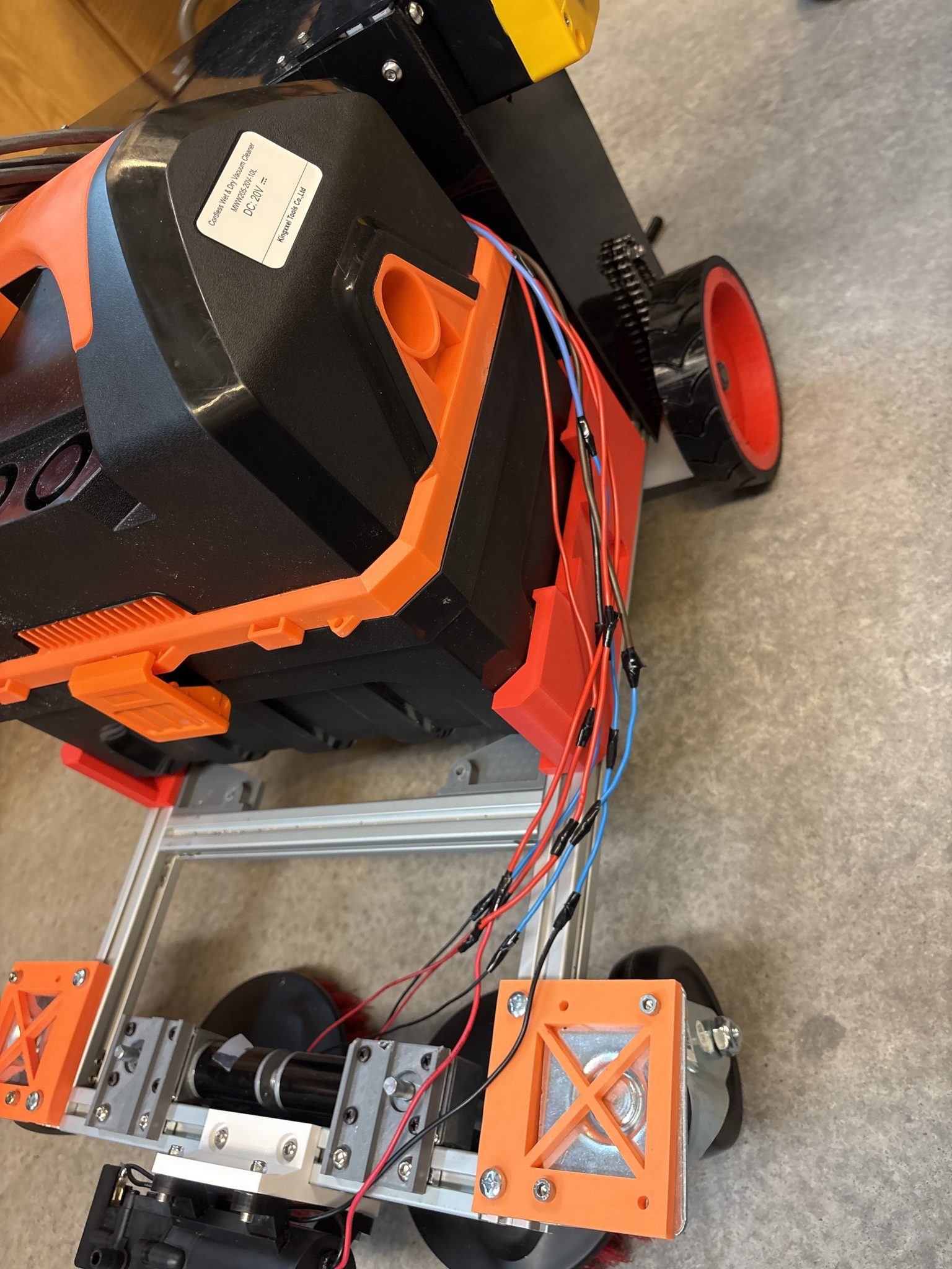
After the connections were secured, Nick and I ran an electrical test to make sure pump and scrubs were working as they were supposed to. During this test it was discovered that I had accidentally used the wrong connection on one of the scrubs and the pump. This was easily fixed as I cut off the connection and then re-soldered the correct connections. Once this was done I updated the Gantt chart to show the completion of the electrical portion and started work on the presentation for GM. I did the progress update presentation as well as the GM presentation.
Next week we have the SICK LiDAR challenge turn in. Due to this, and the fact that I have finished the electrical portion I will be working on making sure that everything we need is ready for the 5-7 minute video.
Week of March 3 – 9 2025
This week was a rather calm week for me. We determined that the current electrical boards would not fit with the ABS sheets that we are using for the water resistant box. Due to this Nick cut new boards that were smaller and remounted them on the robot. Seth then mounted the sheets for the water resistant box.
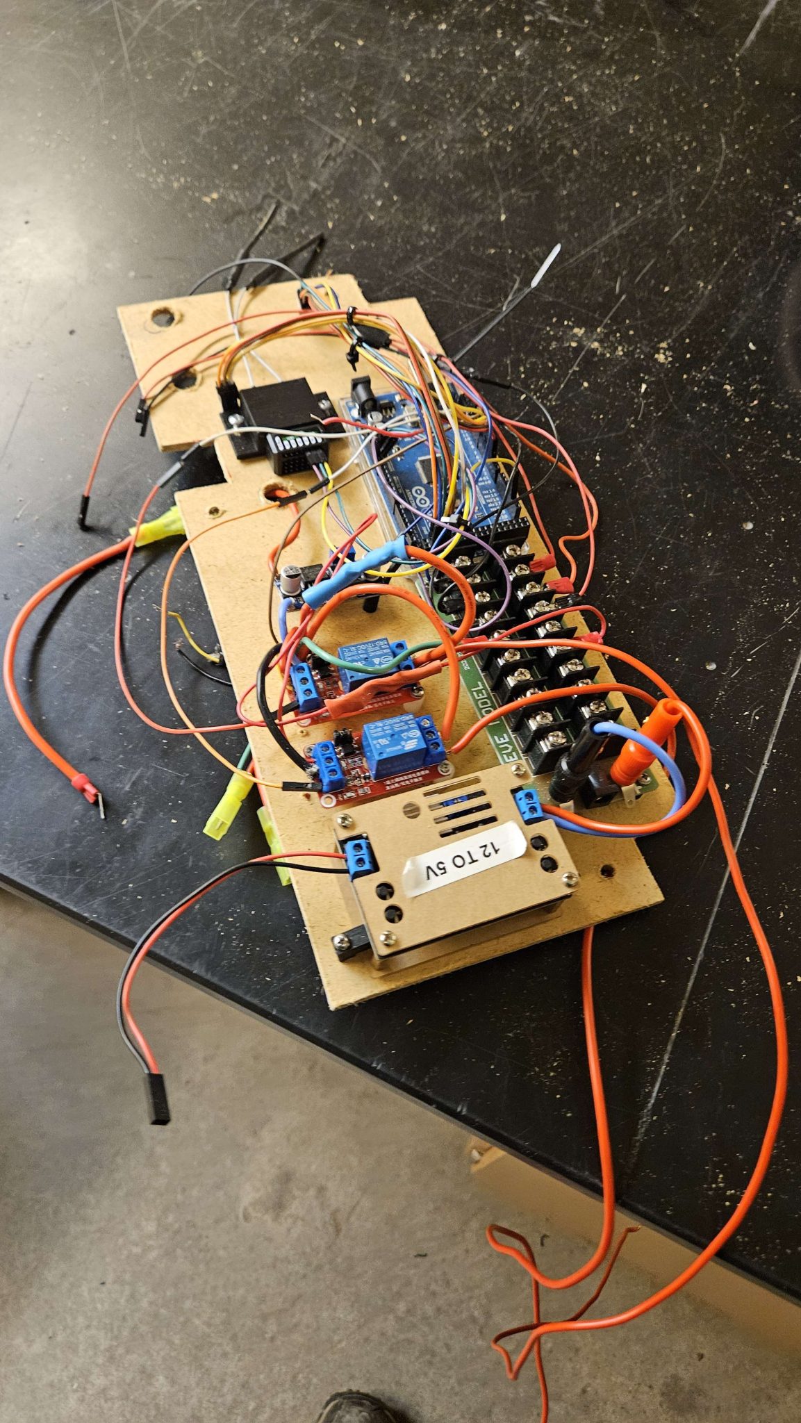
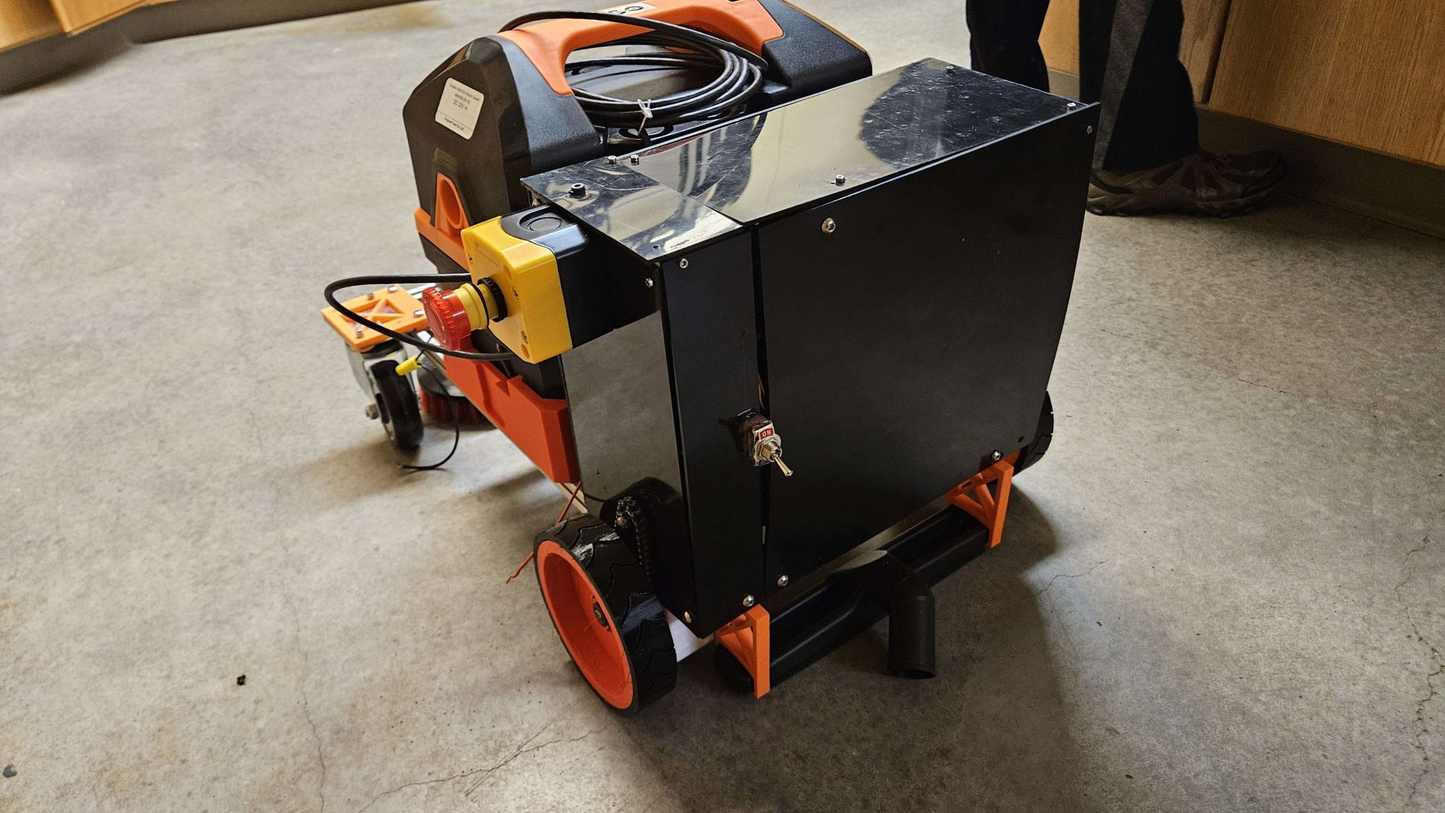
From here I worked on the bottom electrical board with mounting the 24V rail onto it, and drilling a hole for the motor wires to run through to connect to the motor controllers. Once this was done I looked over all of the connections on the boards to make sure that they were all connected and reconnected the universal ground that had been disconnected and the LiDAR voltage connection. Once this was done Nick and I ran an electrical test to make sure all the connections were working. We ran into a slight problem with the E-stop, but that was resolved easily. I also removed the squeegee as it was stopping pressure from being put on the back wheels. I also helped Nick a little bit with removing the pump mount so he could place it somewhere else as well as discussed how we want to mount the reservoir.
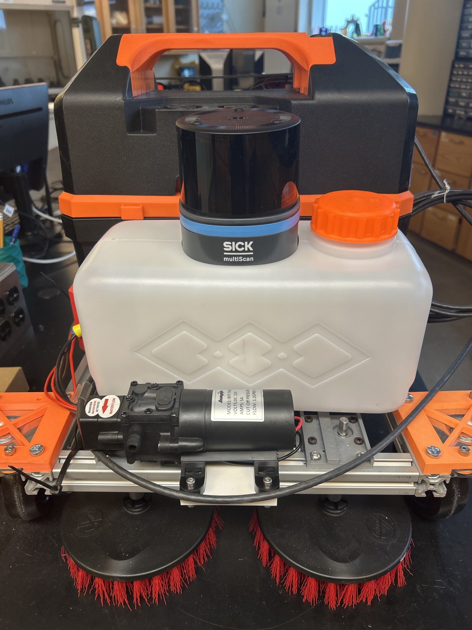
Finally, I reached out to the other Capstone members in the group who are in their final semester to ask when they want to start work on our presentation.
For next week my plan is to finish the electrical by connecting the pump and scrubs, do some market research on other autonomous floor cleaning robots for Sick, and work on the GM presentation as it turned out that the check-in was not on Friday March 7th.
Week of February 17 – March 2 2025
These weeks were interesting. With Spring break in the second week all of the work was done in the first week. After our meeting with SICK we got a few suggestions on things to focus on as we approach the end of the project. They suggested that:
- Talk about how this differs from other solutions
- How much it costs to produce vs how much you would sell it for
- Look at a lot of competitors (Roomba!)
- Look at the market
With the simple use of the LiDAR that we have planned they want market research to play a big role in our submission to them. We have started expanding that portion of our project and I will focus much of my attention on that after the electrical portion is complete. The electrical portion has been making solid progress. Nick, Seth and I have started on the water resistant box for the electrical components on the electrical boards.
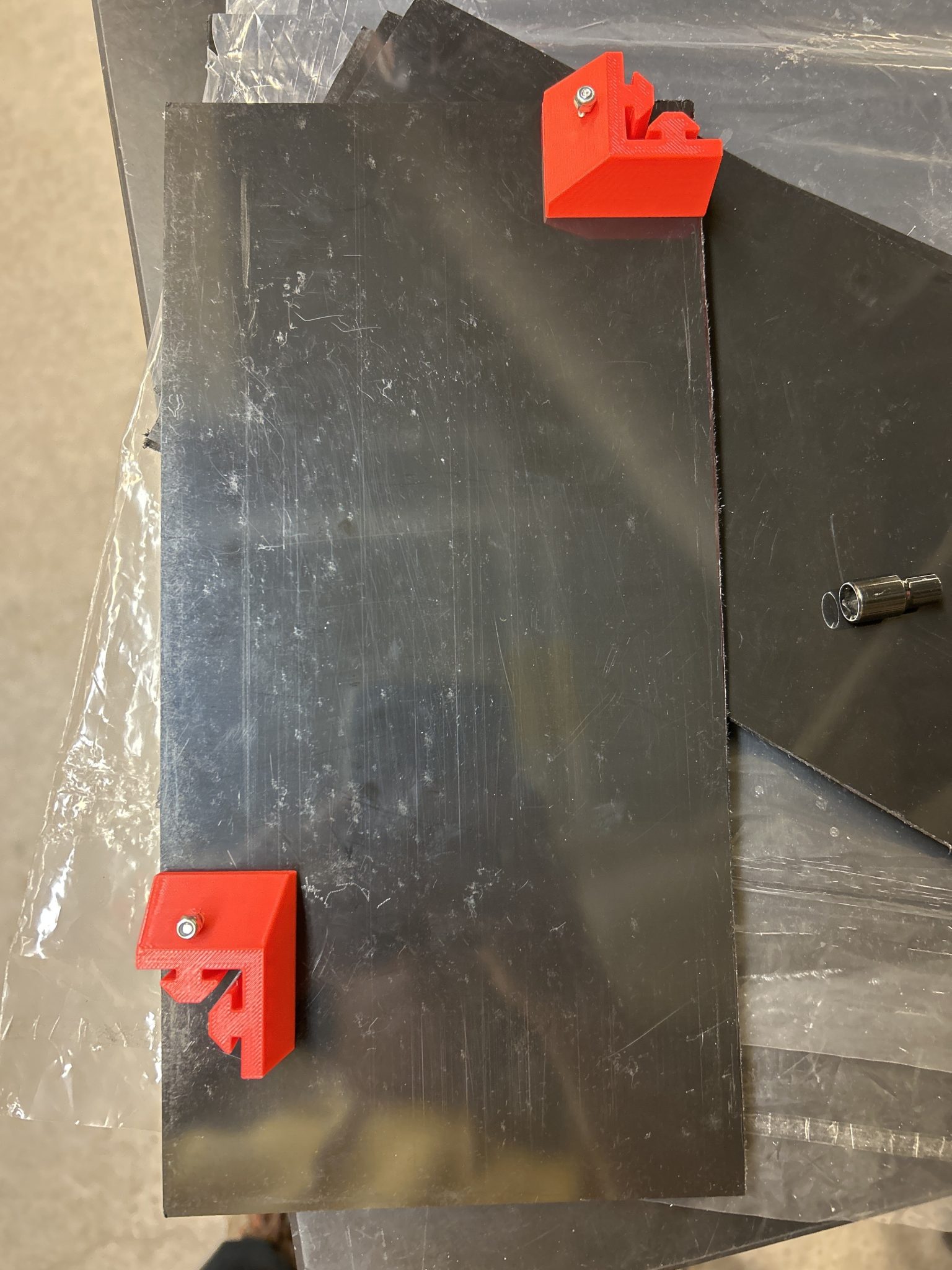
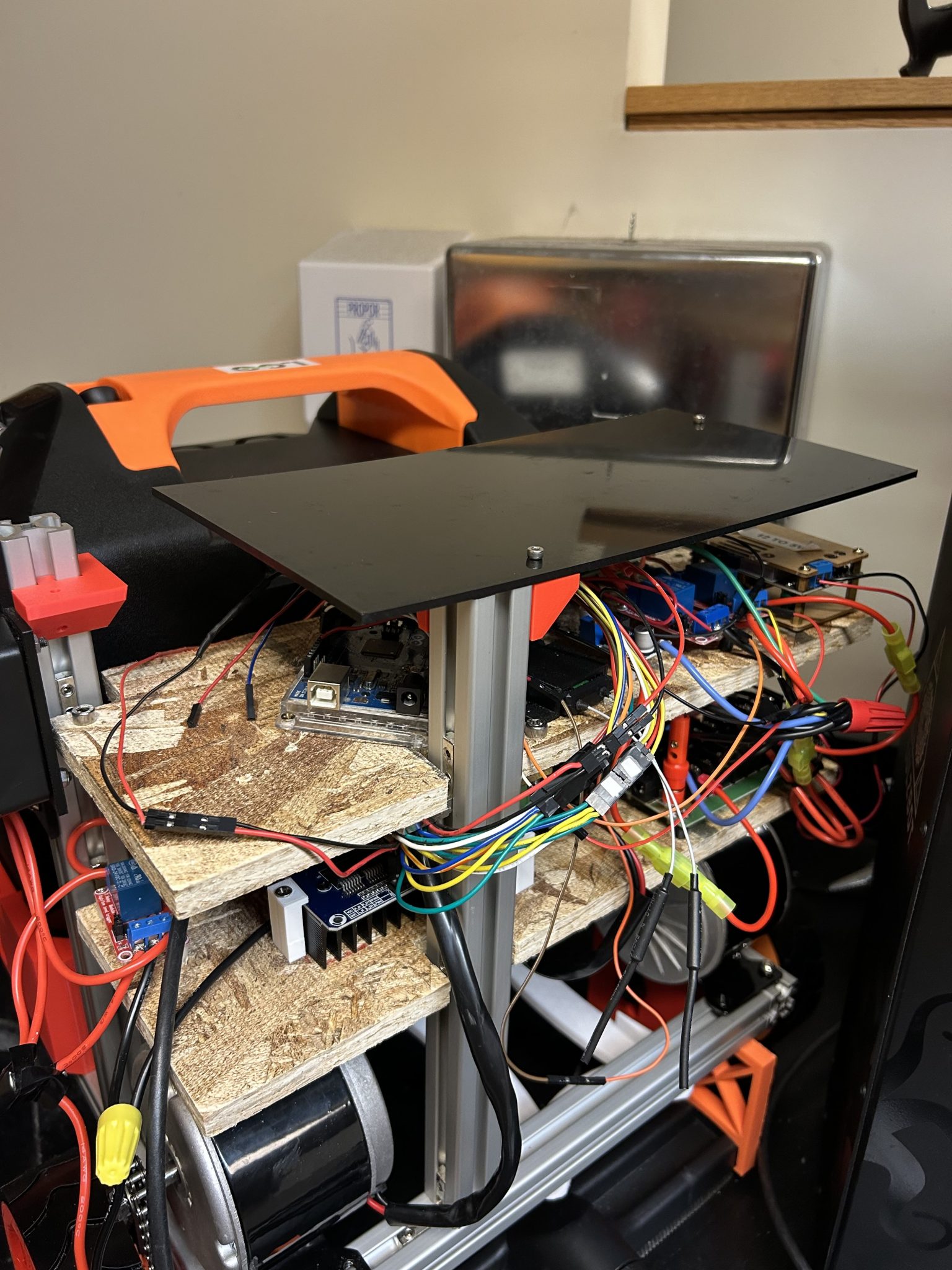
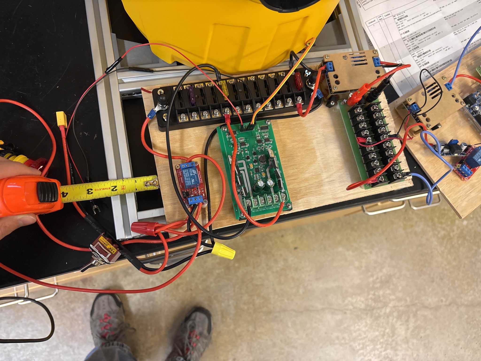
As you can see in the images above though the wires poking out of the sides would have caused issues with the rest of the ABS sheets. To rectify this I drilled holes in the top electrical board and ran the wires that connect the components on the top electrical board to the bottom electrical board through them.
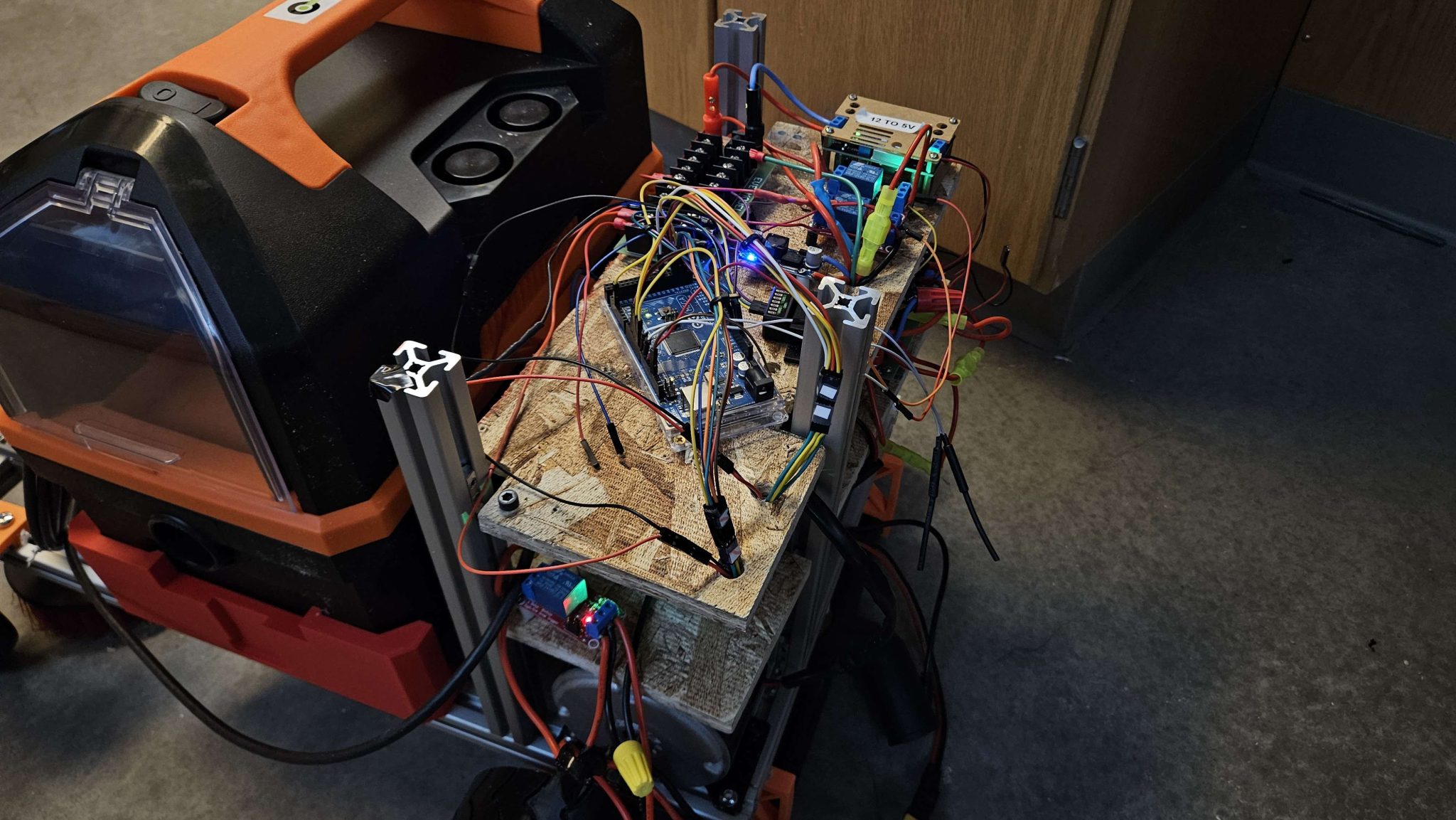
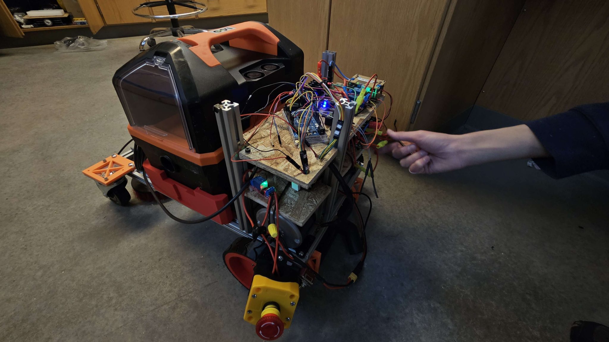
To make sure that all of the connections were still working Nick and I turned the robot on used the FlySky controller run everything. This upcoming week my plan is to finish the organization of the wires. This will be done once Nick prints a new mount for the pump as the wires to the pump and scrub motors are all that are left. I will also work with Seth and Nick on the water resistant box. Finally, I will be working on updating the electrical portion of the Gantt chart and working on the GM presentation we have this week.
Week of February 3 – 16 2025
During these two weeks I was focused on organizing the wiring of the electrical components. Nick and I got much of the organization of the electrical components done. We did this by adding connectors between the two boards for easier removal if necessary and shortening the wires. This part of the electrical process has been making solid progress to completion.
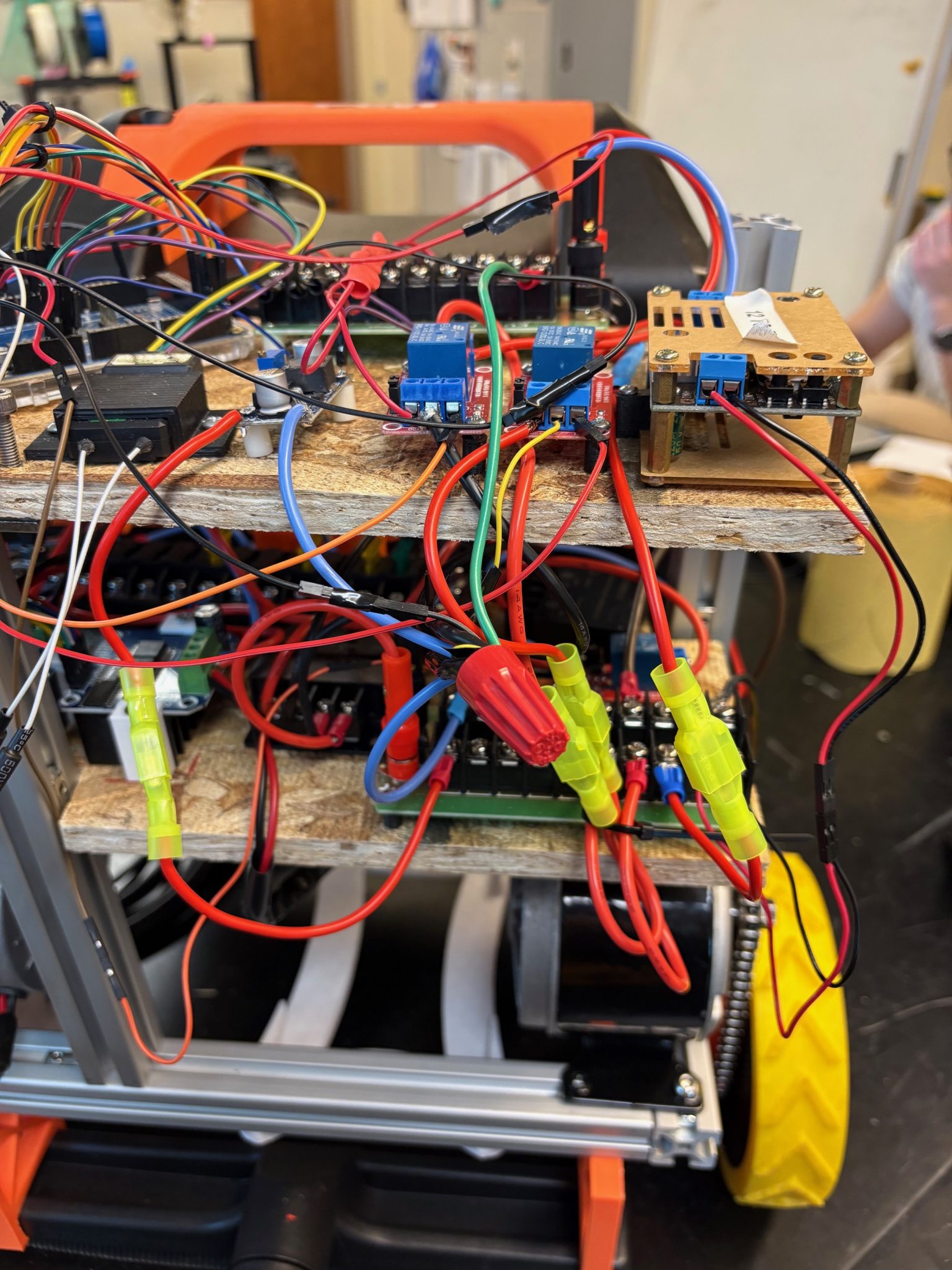
The ABS sheets for water resistant box that we want to put around the electric boards also arrived this week. We have not had time yet to start designing the box. This is due to Seth being busy with the mechanical portion, work still needing to be done on the wire organization and the sheets only just getting here. Nick and I have been discussing that the only issue we see going forward is how to access the on/off switch for the electrical components. However, we think that we can cut a hole in the sheets to get access and then seal up around the switch. Our plan is to finish up the organization of the wires this upcoming week and start work on the water resistant box.
I have been working on the CDR that we presented this week as well and the GM presentation that also occurred this week. As the LiDAR is a complicated component many of the questions were focused on resolving our issues with it. GM wanted to make sure that we were staying on task to meet our goals for this semester so we showed them our Gantt chart. One of our GM contacts, Drew, is on the LiDAR team for GM and he told us to reach out if we need help with anything for the LiDAR.
Next week we also have our progress update with Sick on Monday so we are prepping for that, but we have been making decent progress on the robot and we have looked into the marketability of the robot as they asked us to at our last meeting.
Week of January 27 – February 2 2025
This week I finished the custom Dupont connections between the Arduino and the drive motor controller. I also connected the Arduino to the motor controller using some code that Lindsey sent me that showed what needed to be connected.

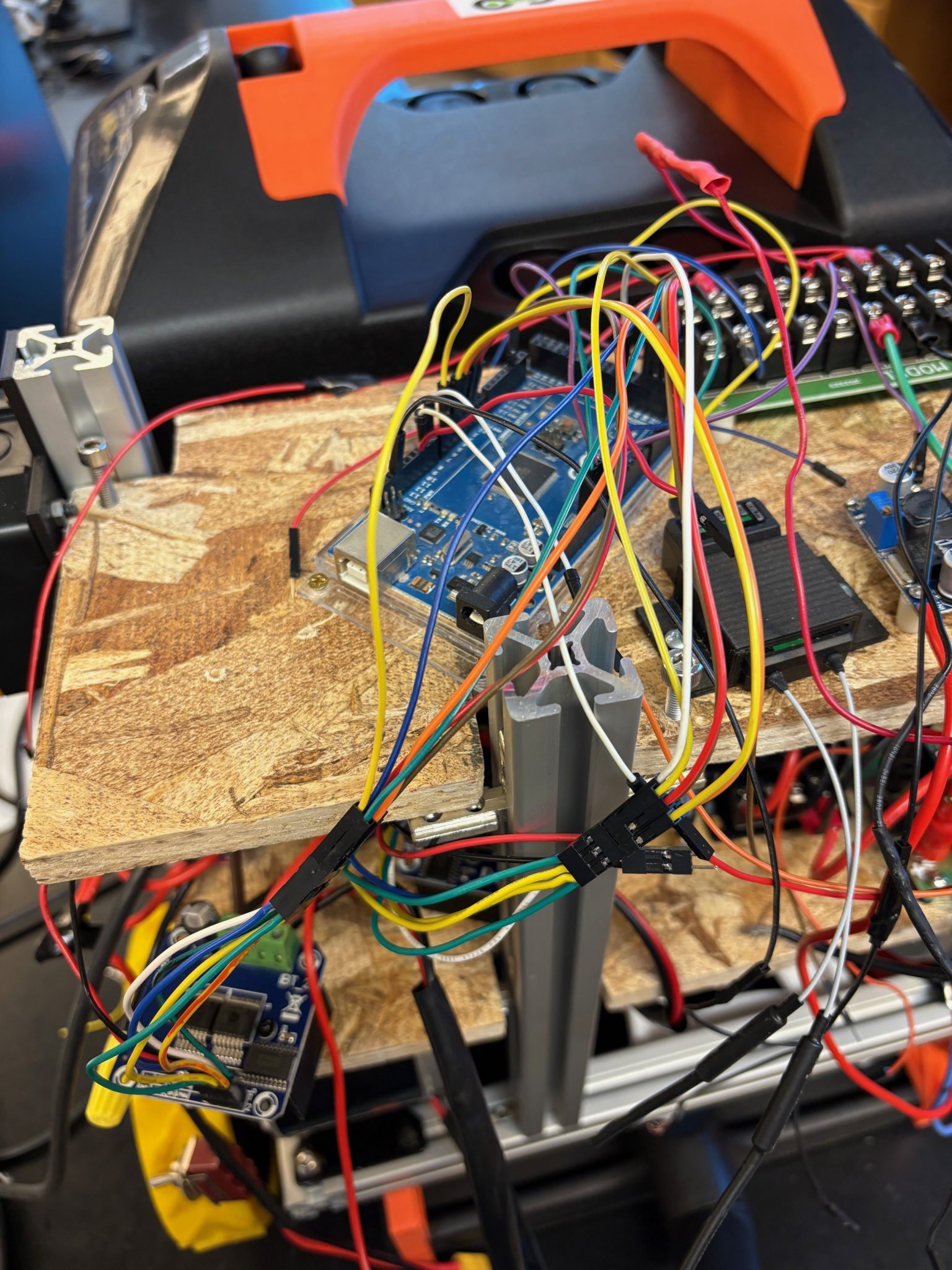
I also met with the other members of the Husky-Clean group. We wanted to discuss the final design of the robot as well as the issues we are having with the LiDAR. We were found a new water supply tank as we decided that the current bladder that we have cannot be used as we can no longer put it in the vacuum. I found the one we are going to use which is about 5 L and can be found here New water reservoir. We also made a basic design of how we want to mount it.
Wesley made a more complex design on our CAD design. The decisions that we also made to finish the project were:
- LIDAR bracket on top of water reservoir
- Acrylic under guard for LiDAR to block water
- Working on water cover as soon as acrylic arrives
- Repositioning the pump with a more secure mount
- Finish Dupont connectors when wires arrive
- Add an ultrasonic sensor to front of robot to cover LiDAR blindspot
Finally, I worked on the GM progress update report presentation and spoke of the progress the electrical portion had made. Next week I plan to continue with the organization of the wires and probably start designing the water resistant box.
Week of January 20-26 2025
This week I worked on the motor controller connections to the Arduino and to the 5V rail with Nick. We did this to make he connections easier to remove when we have to remove the electrical boards.
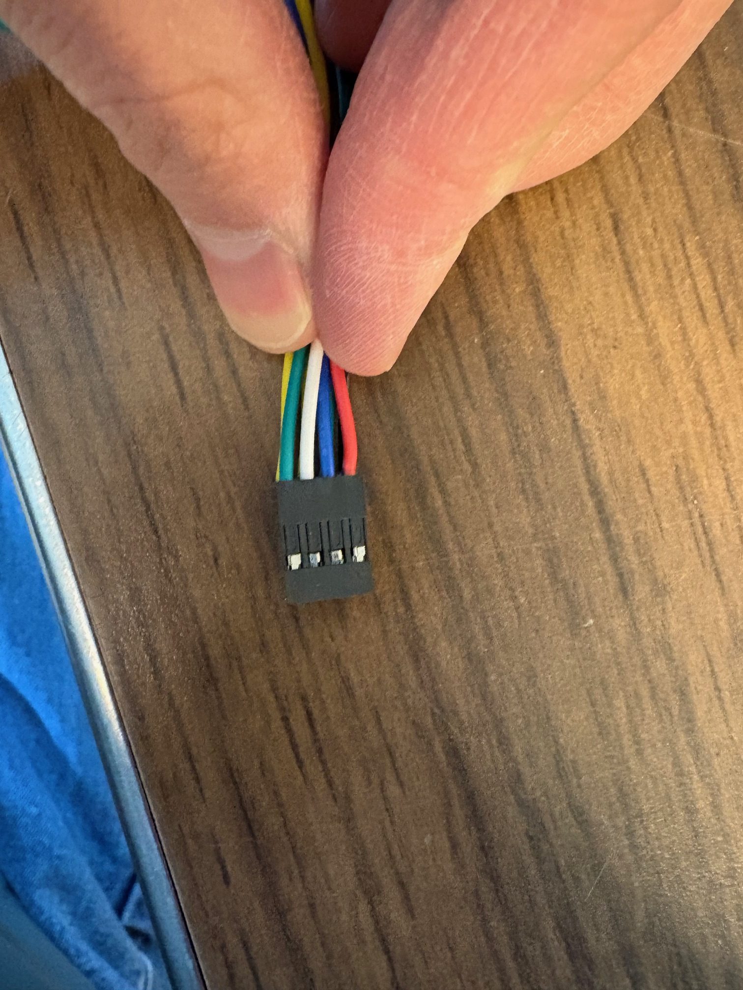
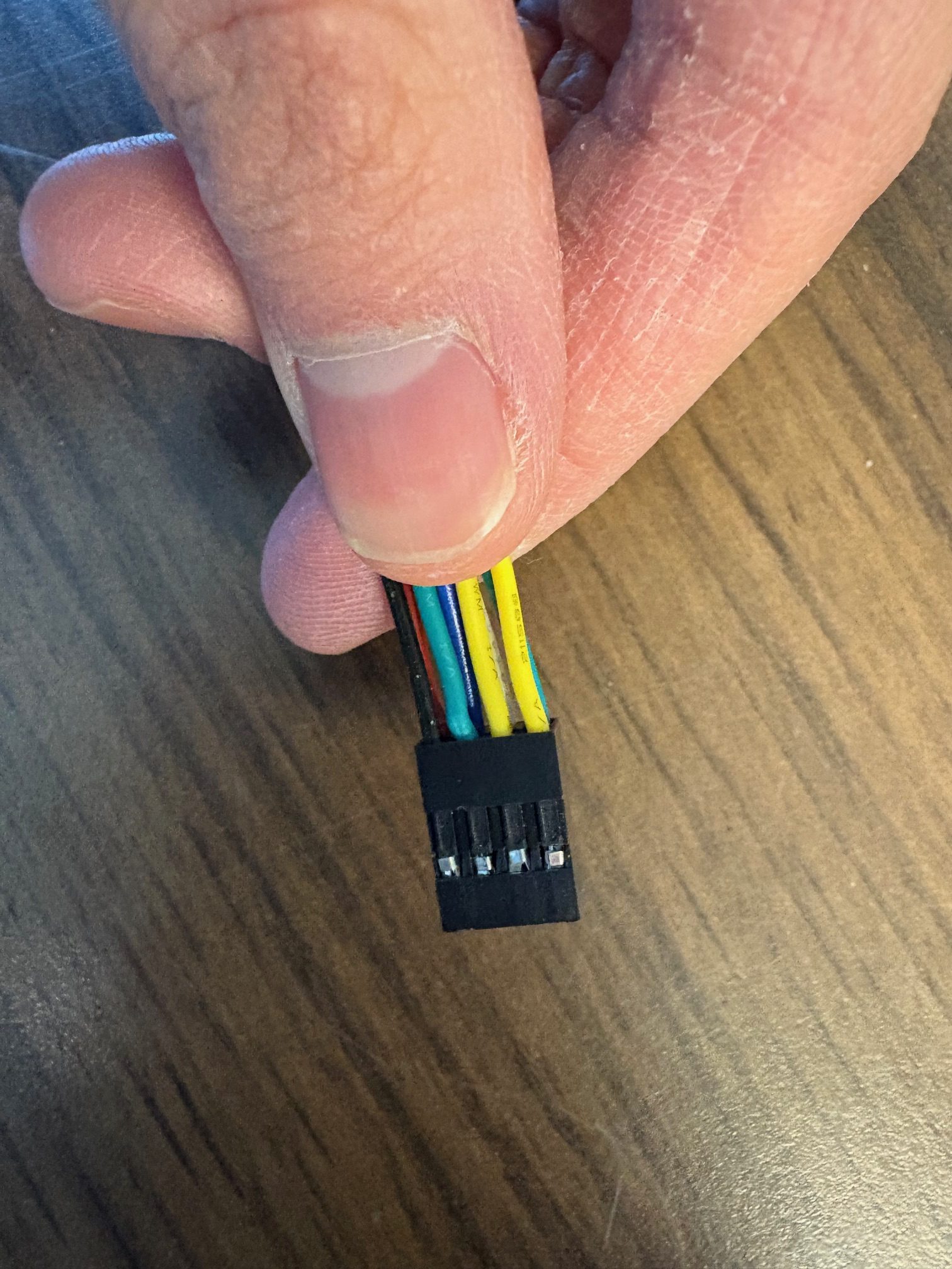
I also worked on connecting the LiDAR to the 24V rail. As the LiDAR can handle between 9-30V DC the decision was made that it would be better to have the LiDAR attached to the rail with fuses. I put a 2A fuse as the the LiDAR cannot handle more then that current.
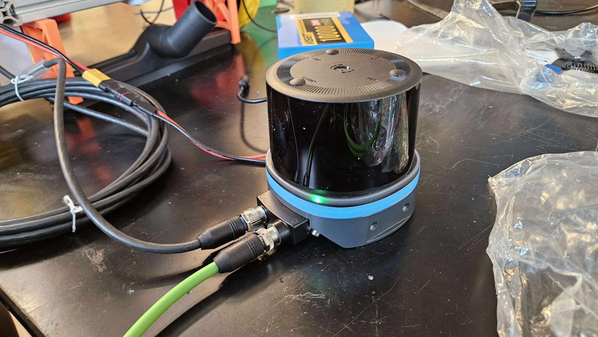
Finally, I talked with Nick about how to hard mount to drive motor controllers to the electrical board. He suggested that we 3D print mounts and I agreed that, that was the best idea. I also worked on the proposal to GM for more funding. As we have a few new components that we need, and we needed to replace the vacuum and the Raspberry PI. We requested $250.00 for the following items:
- Raspberry Pi 4b 8g: $80.00
- 24V Relay: $8.00
- Acrylic Sheets 24”x36” 3mm: $70.00
- Raspberry Pi Power Cable: $10.00
- Reservoir: $30.00
- Potential damaged components: $50.00
I also met with Jeff so that I could be caught up on the filament storage solution they had started work on last semester. For next week I want to continue work on the organization of the wires, work on the GM presentation we have, and try to come up with a way to potentially mount the LiDAR. The only issue for next week that I can see that might occur is that Seth needs to finalize the mounting of the new vacuum.
Week of January 13-19 2025
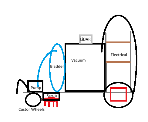
For this week and the next week the plan for me is to focus on the electrical. I have started with making the wiring between the components more organized and clean. This is because the wiring was going everywhere last semester so that when we were running the robot someone had to hold the wires clear of the moving parts.
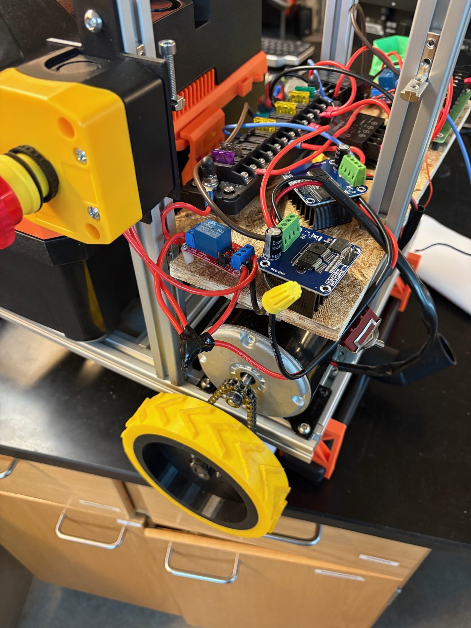
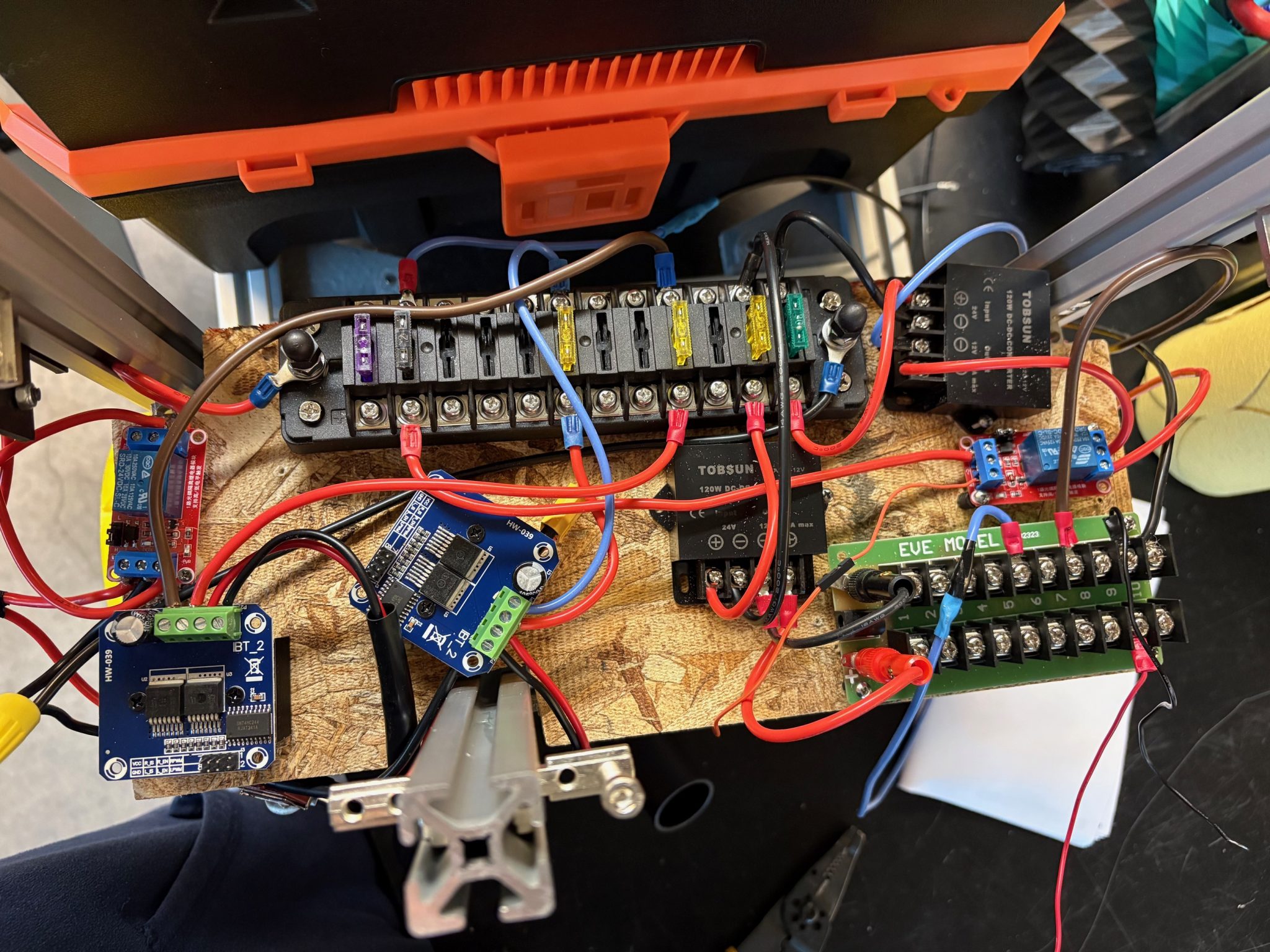
I have discussed with Nick and will continue discussions with him and working with him on the best way to optimize connections between the boards. We have come up with a solution to the motor controller connections, but the others still need some work. Nick, Lindsey, and I spoke with Dr. Tony Pinar on how to wire the LiDAR as we were not sure on that. He gave us some wiring diagrams that a senior design team of his used and that helped us figure it out. We have now connected the LiDAR to the system and it is ready to collect data.

Finally, I have been in discussions with Seth and Nick on how to make our electrical boards water resistant. The current idea is to make a box out of ABS sheets, but we have not made any final decisions.
Week of November 11-17 2024
This week I made the final wiring diagram for the Husky-Clean. I also met with Nick to finalize the electrical system before our design check-off.
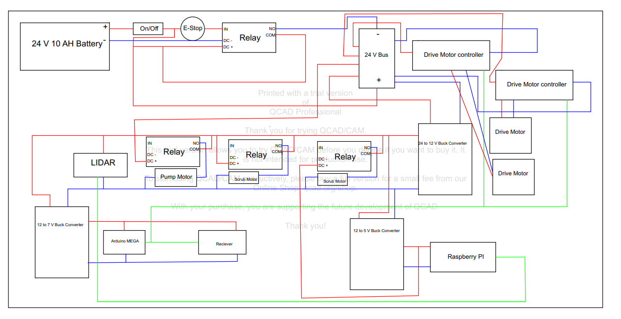
With these done, the group met to get everything ready for our check-off on Tuesday. As our check-off was at 7pm we met at 5pm and made sure everything that needed to be in the OSF repository was there, all the connected electrical components were working, that the code was working as expected and that all the mechanical parts were on the robot. The OSF repository can be found here: https://osf.io/kte4s/ it goes over all our 3D designs, our code, and our electrical wiring. Nick and I also discussed new drive motor controllers and got them ordered. My plan for next week to now that they have arrived to attach the new motor controllers, work on our progress report presentation to SICK, and our progress report presentation to GM.
Week of November 4-10 2024
This week our second drive motor controller arrived. I got it wired to the rest of the electrical components and put on the electrical board that Nick cut.
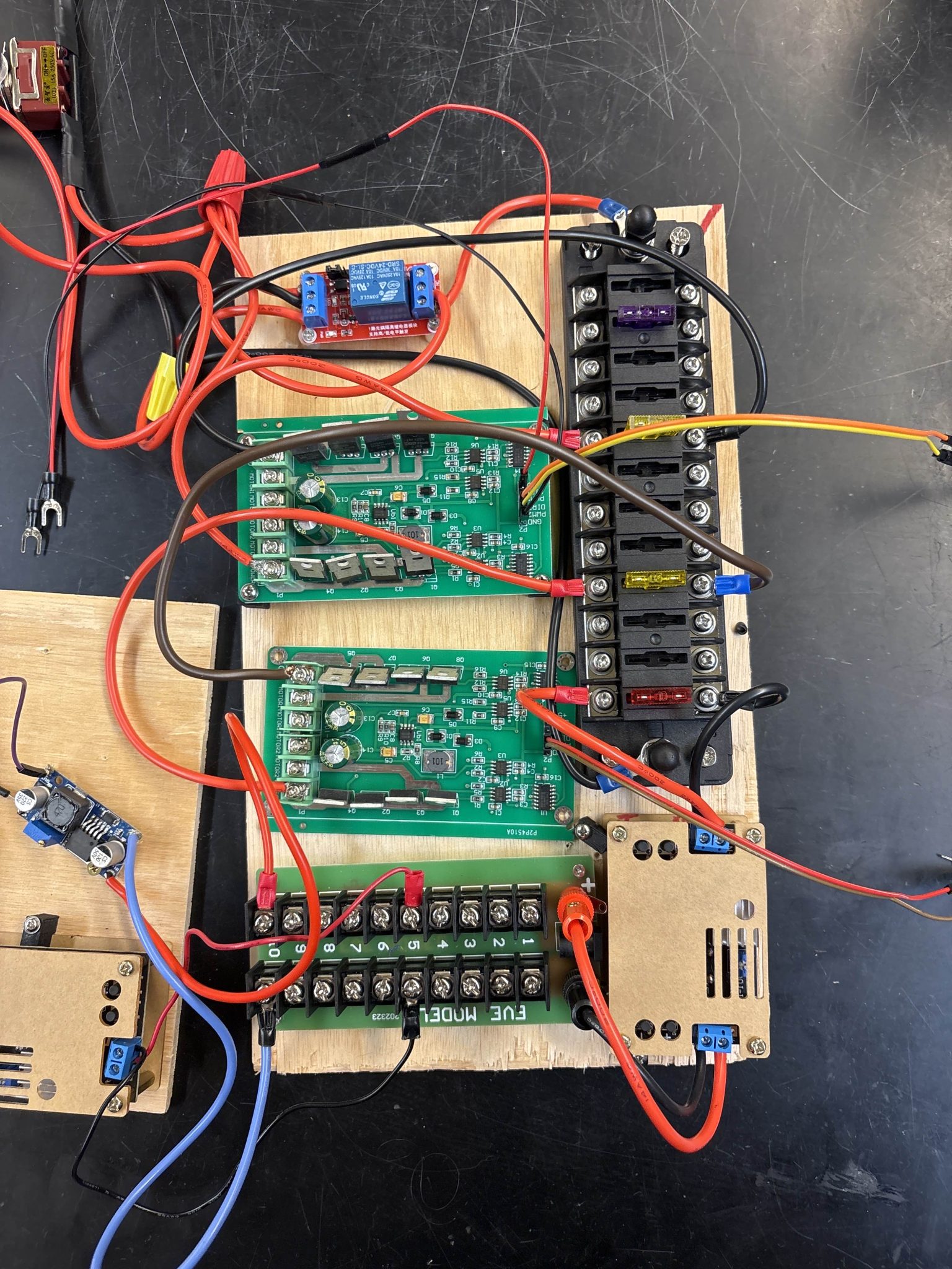
The group met on Tuesday and Nick, Donn and I learned that the current electrical board which was a 7×14 inch board with 1×1 in cuts at the corners was not going to work. We discussed with Seth possible other boards and we came up with two 5×14 in boards with cuts in the back corners. Nick cut the boards on Wednesday and then I mounted the electrical components to the new boards.
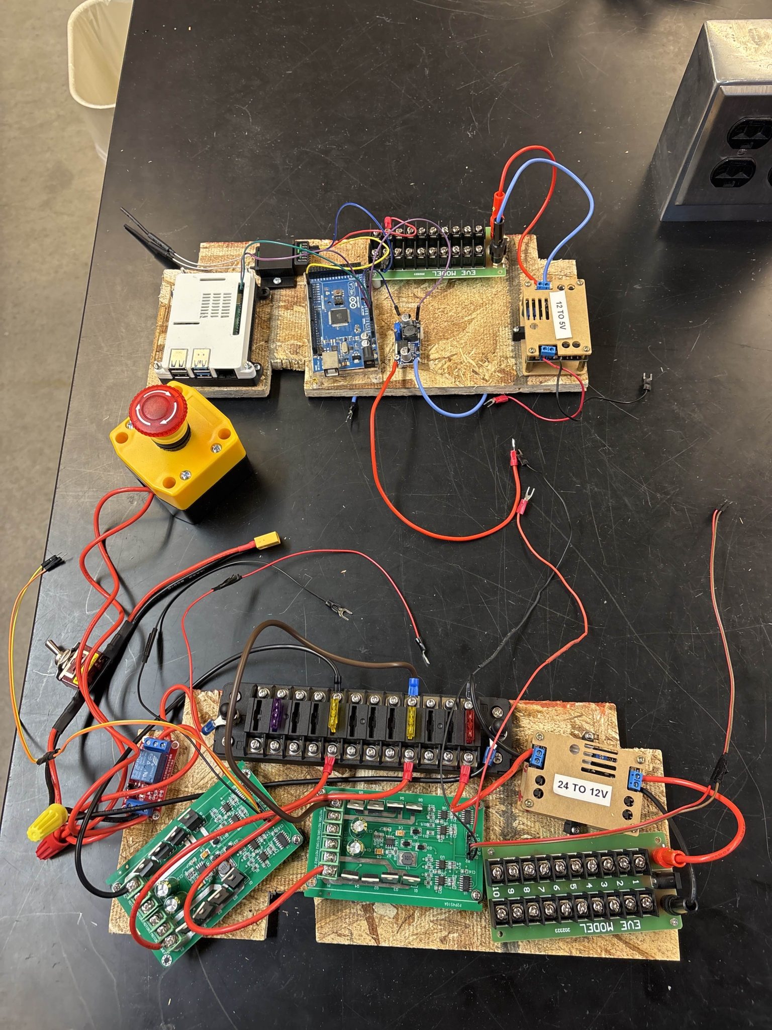
Since the posts for mounting the electrical boards were not yet cut we could not mount the boards onto the robot on Wednesday. However, Seth cut the posts on Thursday so I was able to mount the boards and connect all of the electrical components to each other.
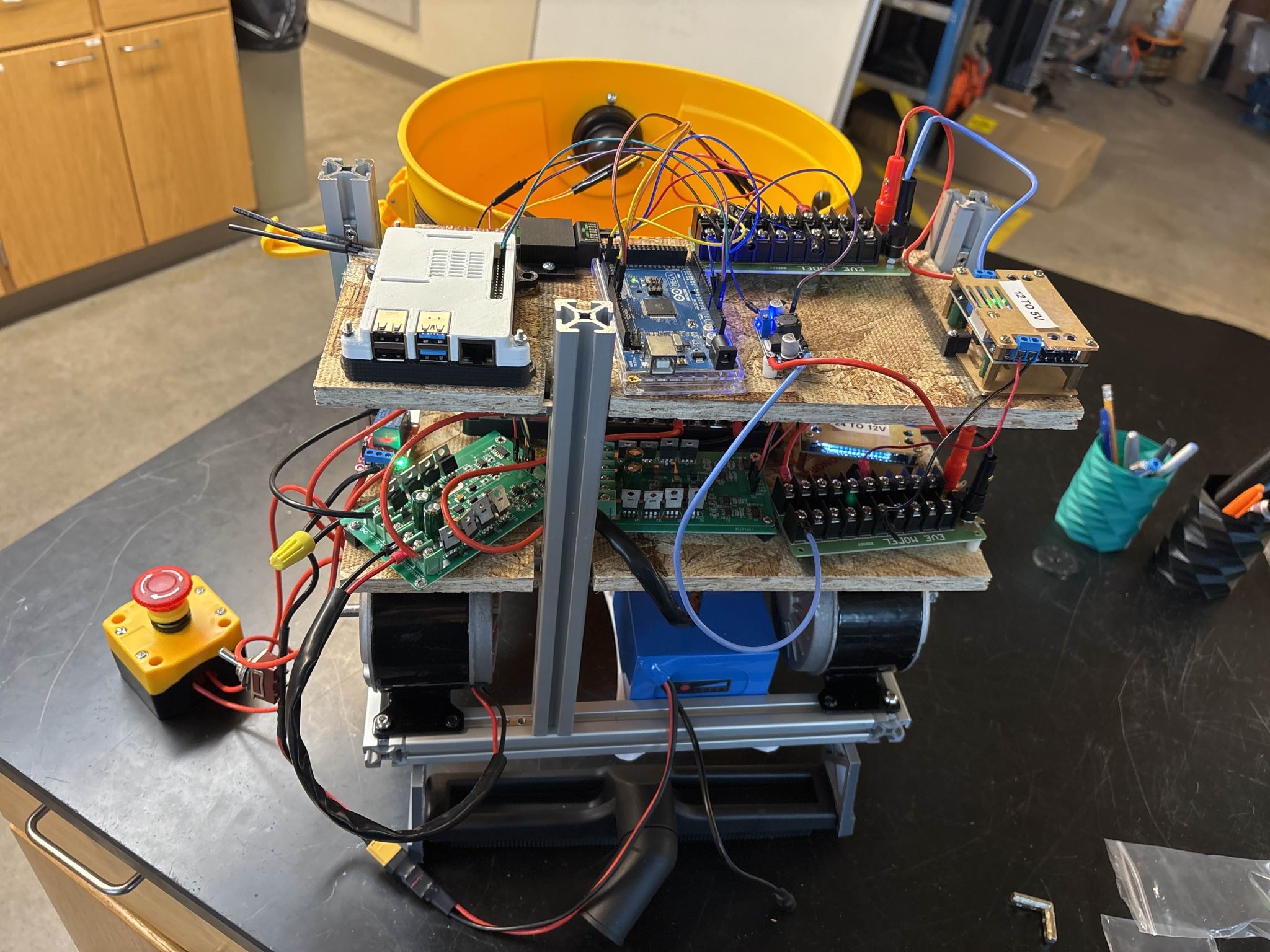
We were having a small bit of trouble with the E-stop and one of the motors constantly running. Nick flashed the code on the Arduino and that fixed the constant motor running issue, and I came back later in the day and rechecked the connections and the E-stop was working. However, Nick and Lindsey tried to test the drive motors to get them to work and for some reason the motor controllers were not working. The new one seemed to have not completed connections and the old one just stopped working. I tried to test the old motor controller on Saturday, but it still was not working. The new motor controller now blows fuses whenever we try it, so we have started to look for new 24 V motor controllers as we tried a 12 V motor controller and you could hear the motors attempting to spin. Next week my plan is to look for new motor controllers, as well as present to Dr. Shane and make a progress update to GM.
Week of October 28 – November 3 2024
This week I discussed with Nick, Donn, and Seth how we want to mount the electrical components and the battery. We agreed on a 3D printed battery mount that Seth agreed to make. We also decided to layer the electrical board onto two boards that were layered above the battery. Nick cut the boards on Wednesday and then he soft mounted the electrical components. I came in on Wednesday and Thursday to wire the components and make sure that the boards are able to be mounted the way we want. The wiring went as we expected and when we plugged in everything worked as it was supposed to.
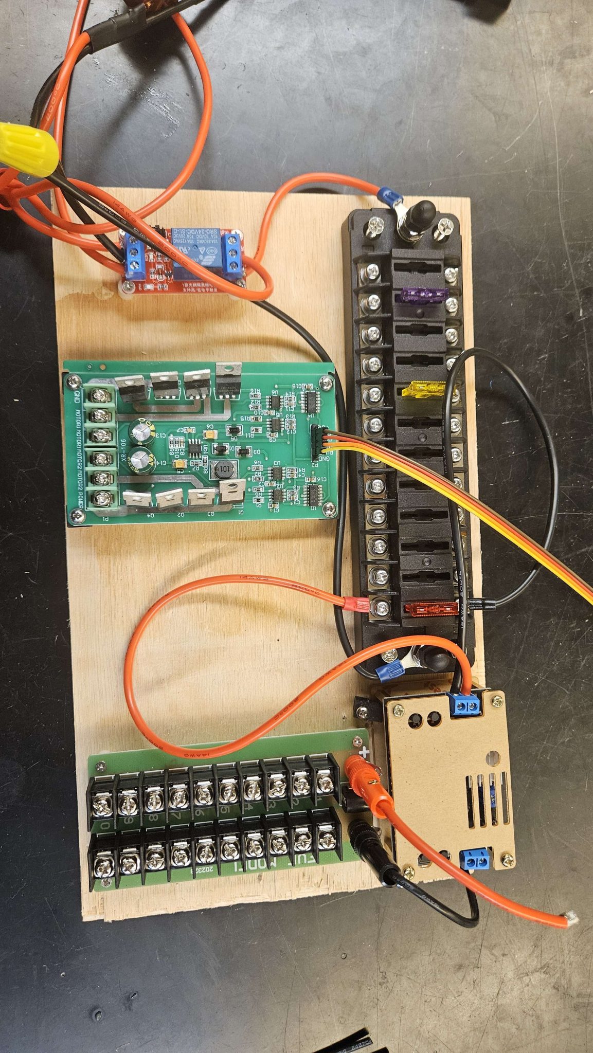
As we want to use L-brackets from posts coming up at the corners we will not be able to use the current boards. I went with Donn to the Makerspace to cut new boards that are 14 in x 7 in with 1 in x 1 in cut outs at the corners. However the coaches there told us that it was closed until Monday and as neither of us were trained on the power tools we could not cut the new boards. Nick said he could cut them on Monday as he is trained on some of the power tools there. The new motor controller also should have arrived, but when I checked on Friday at 4:50pm it was not there yet, so my plan is to check Monday and hopefully be able to wire it. I also did some research for my lab manager role and found a new ESD mat, brass wire, and a brush. I also cleaned the soldering station. I also presented on the progress the electrical team has made to GM this week. Next week my plan is to get the electrical components wired and mounted on the robot so that we can attempt driving it.
Week of October 21-27 2024
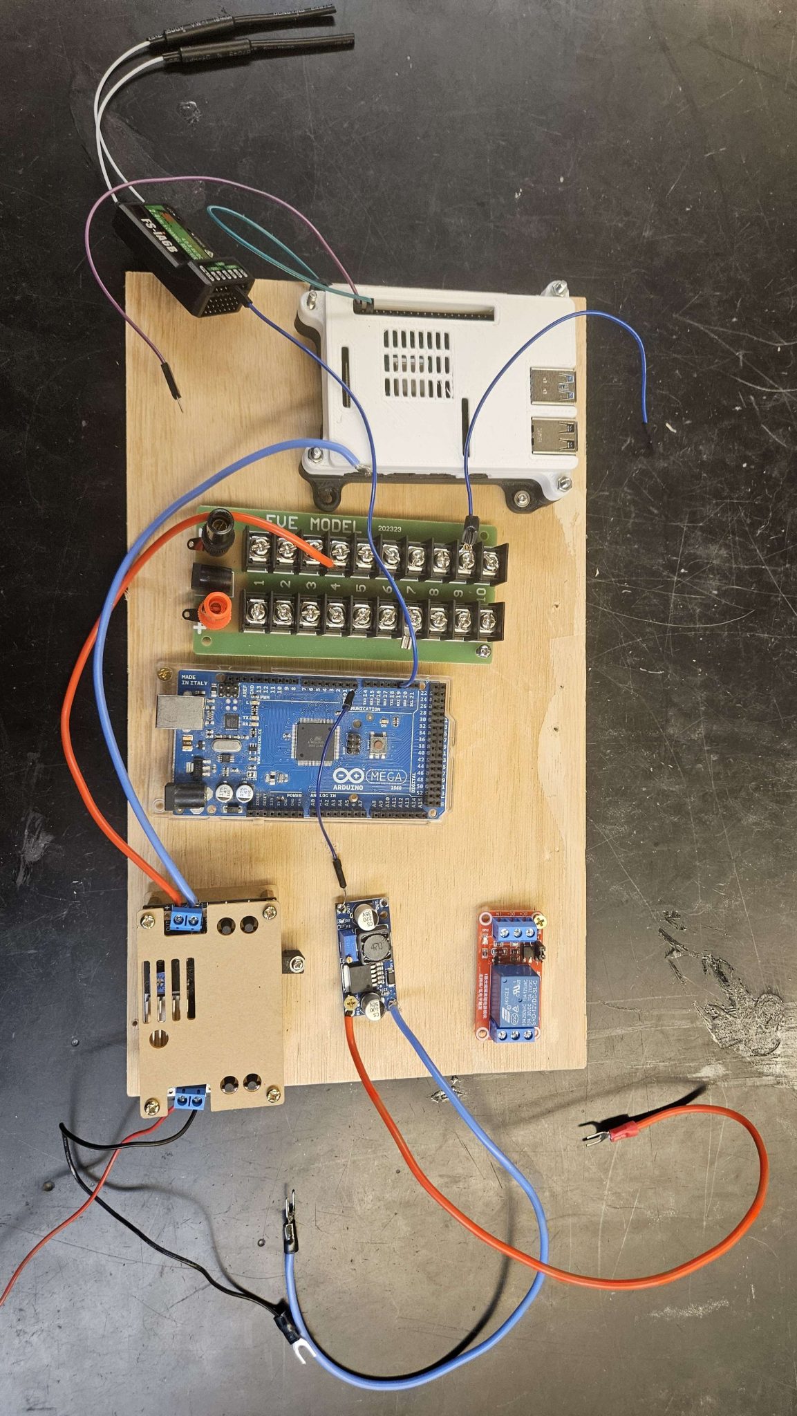
This week we ordered a new motor controller for the drive motors that is coming in next week. I also continued wiring the rest of the electrical components and removed the wired components from the first board. I connected the 5 V line and the 7 V buck converter. From there I connected the 5 V line to the drive motor controller and the Flysky receiver. The pump relay has also been connected to the 12 V line, and the Raspberry PI has been connected through the GPIO pins to 5 V.
Carson also reached out about what I need to do for my lab manager job. For next week my plan is to finish wiring the electrical components like the LIDAR and second motor controller, I also need to start working on how to mount the electrical components.
Week of October 14-20 2024
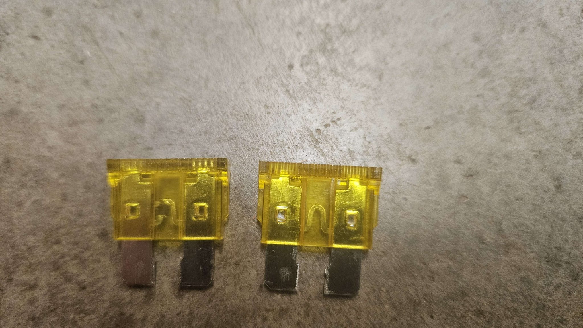
This week I worked on the electrical portion of our progress update slide for our sponsor GM EMI. The inverter we ordered also came in and the team met on Tuesday to see if we want to use it. It was eventually decided that the inverter was too big for the frame and shop-vac and we would start looking for a battery powered shop-vac or run our current shop-vac off of a wall outlet. We also attached the drive motors and I attached the electrical board so far to the frame for the shop-vac. We wanted to test the motors to see if they could run with some weight on them. They were not working on the day we were testing so Nick came in at a later day and found that a fuse had blown on our 24 V bus.
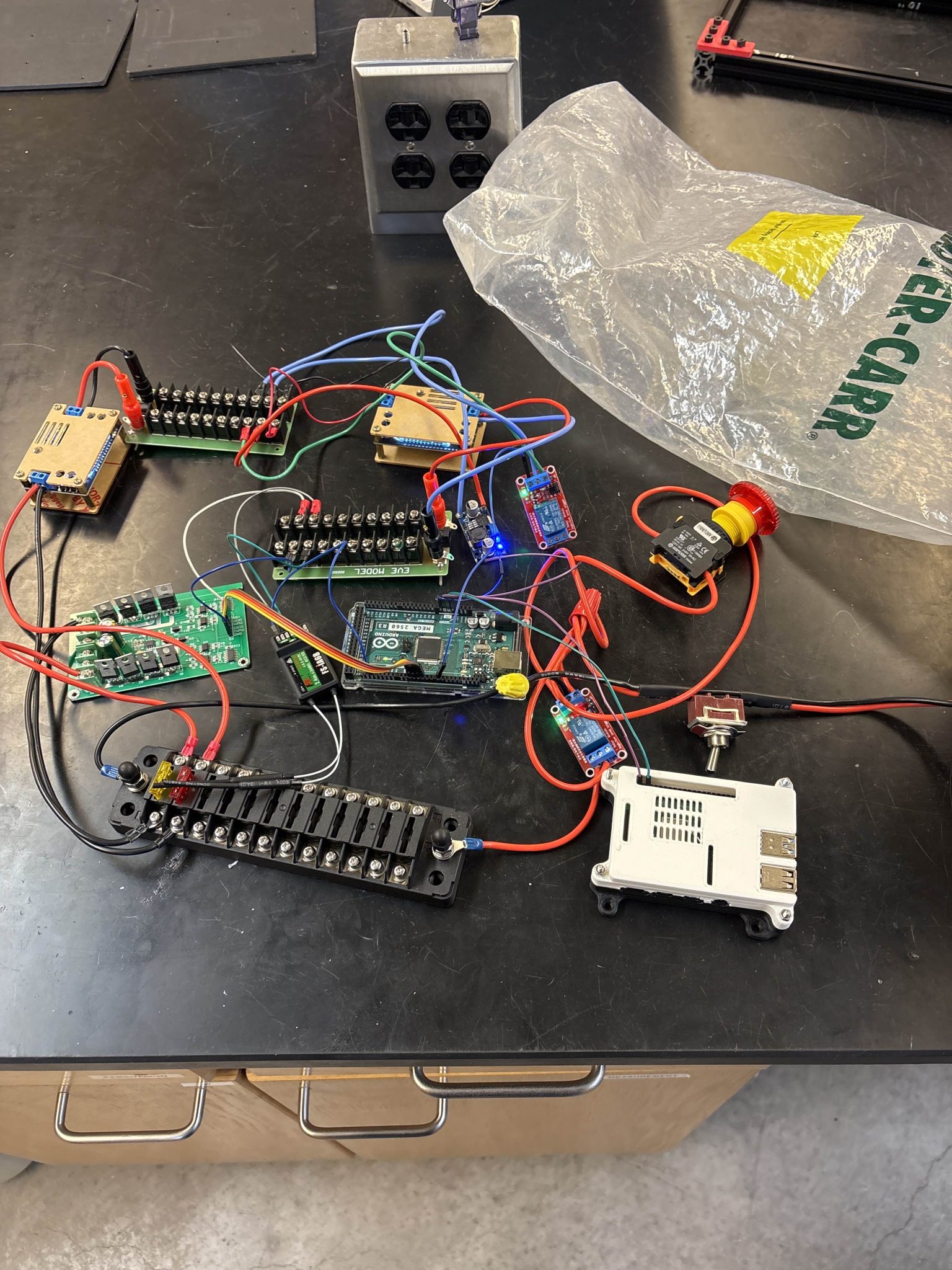
We then met later in the week and continued with testing. We ran into an issue where one motor was working as it should from the Flysky commands and the other motor was either continuously as soon as the Arduino MEGA got power, or it was not working at all.
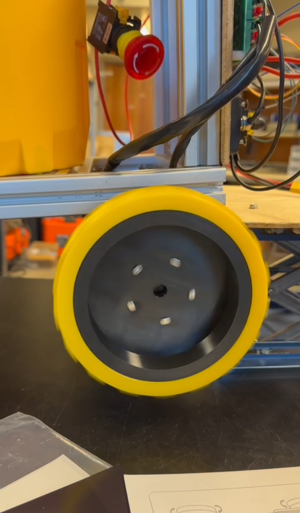
I went to the lab on Thursday to try and figure out what the issue was, but I could not determine what was wrong after testing the current and voltage that was going to the motors. Due to this, Nick, Donn, and I met on Friday after our meeting with GM to do some troubleshooting. We started with a few suggestions the engineers from GM suggested to see what was going wrong.

We first used a DC voltage supply to directly supply the motors with 24 V to make sure they were working right. They were working as they should with each motor drawing about 0.5 A of current.
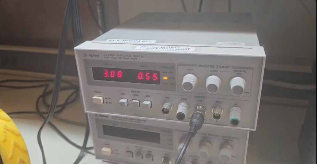
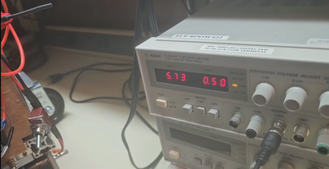
Once we determined that the issue wasn’t with the motors we tested the motor controller, and realized that the motor 1 port on it was drawing no voltage. To make sure that it was a motor controller issue we tested the PWM outputs from the Arduino using an Oscilloscope. Both outputs were receiving square waves from the Arduino, so we tried switching with the output 1 getting a higher frequency and pulse width. To determine if that was an issue we tried flipping the signals going to the motor controller to see if the different signals were causing the problem, but it was not. Having determined that the problem was the motor controller we started a discussion on the possible solutions with the agreement that we would make the decision next week. We came up with three possible solutions:

My goals for next week are to get the new motor controller so we can test if the drive motors work, continue the wiring of the 12 V components, start the wiring of the 7 V components, and discuss how we will mount the electrical board.
Week of October 7-13 2024
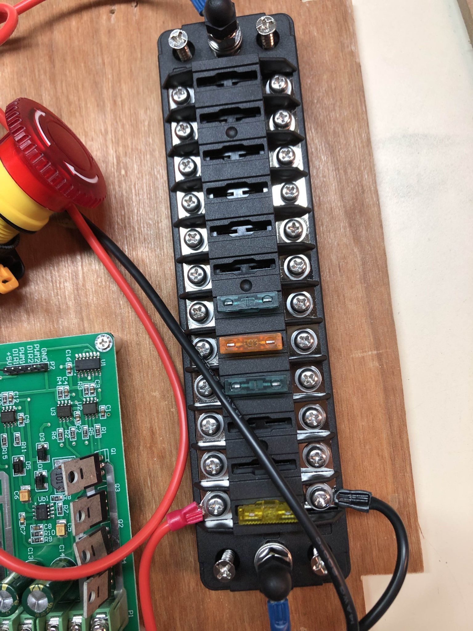
This week the team met on Tuesday to discuss progress on the Husky-Clean. We then decided to head to the lab to see if we could get the motors running with the Flysky controller. I wired and mounted the drive motor controllers, and mounted the 24 V bus, and the relay.
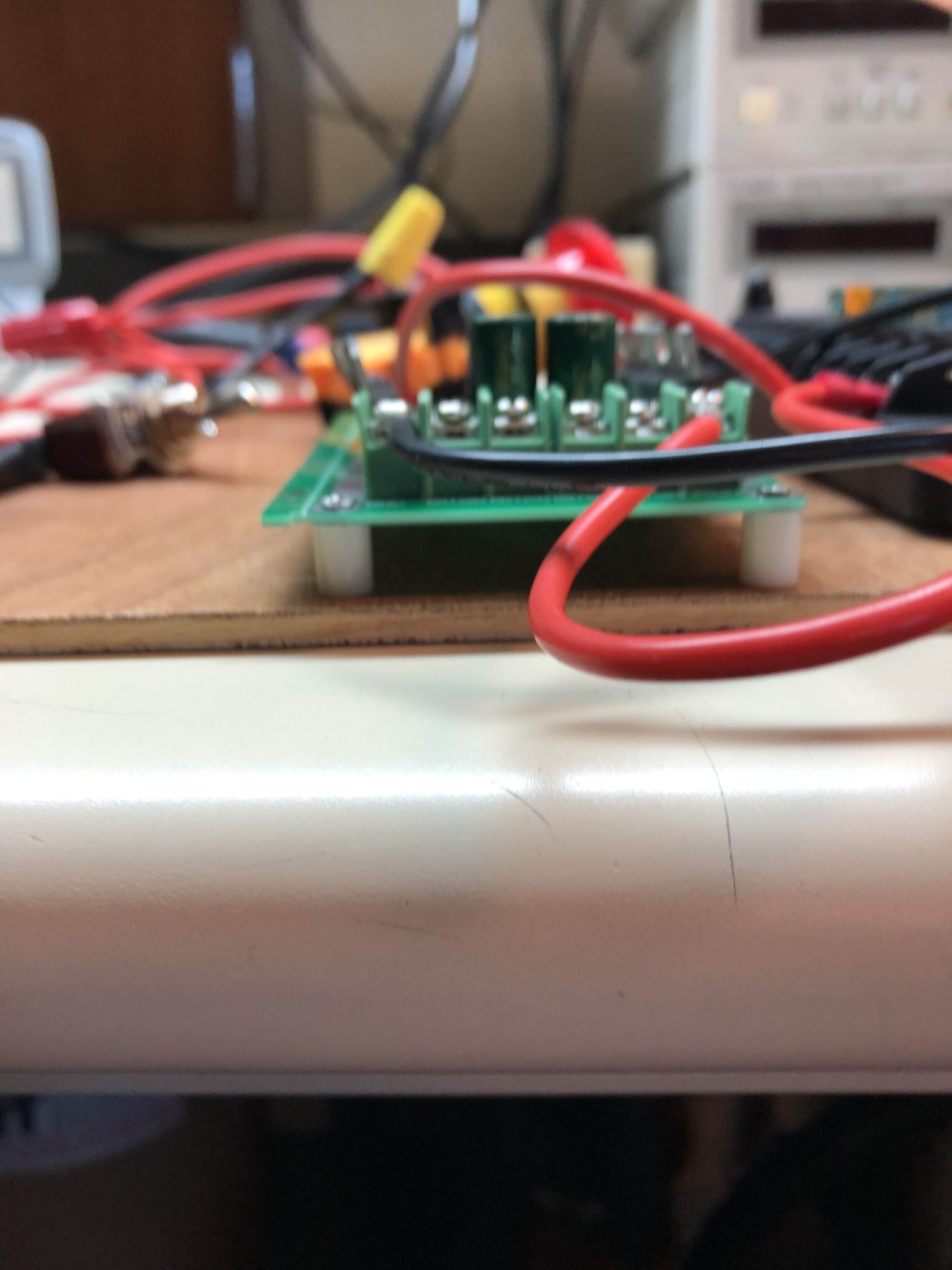
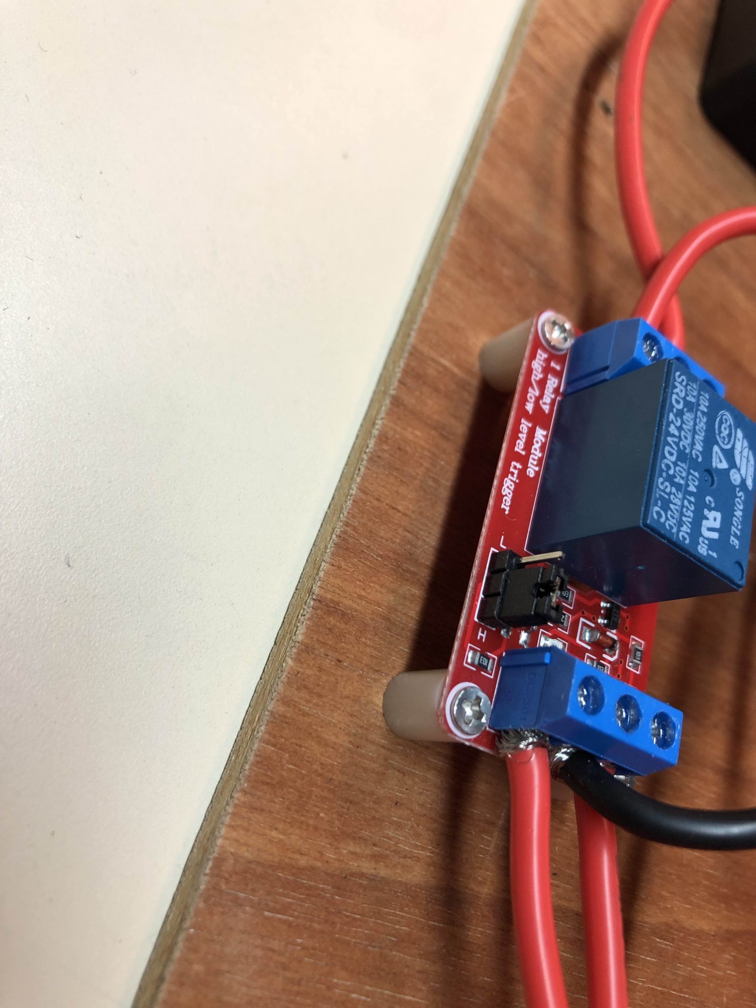
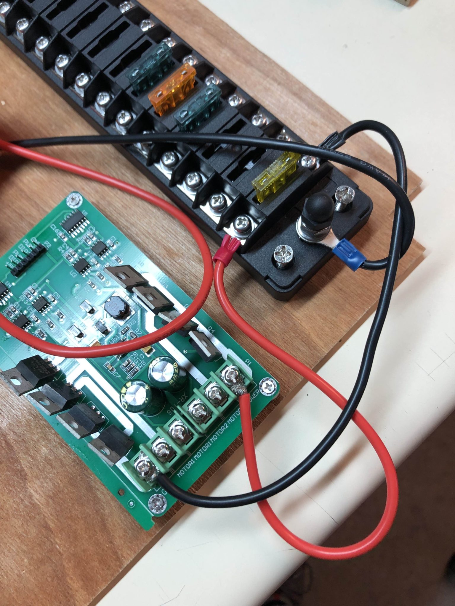
After this much of the team had to leave so we were not able to test the motors on Tuesday, but we agreed to meet later in the week to test them.
On Thursday we met again to test the motors. I wired the 24-12 V buck converter while Lindsey worked on the code for the Arduino MEGA and tested it with Nick. However at the time the motor was not running, and we could not figure out why. I looked at a schematic of the motor controller and realized that it needed to have its 5 V and ground pins plugged in from the Arduino. I also fixed an error I had made in the wiring diagram I made.
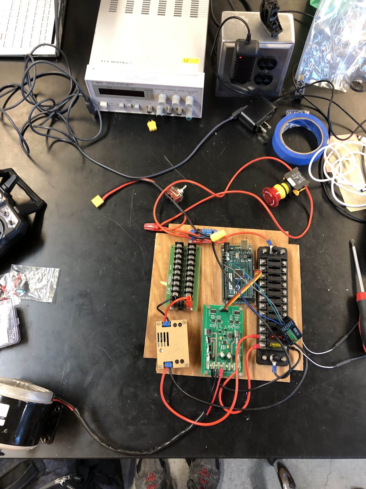
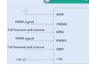
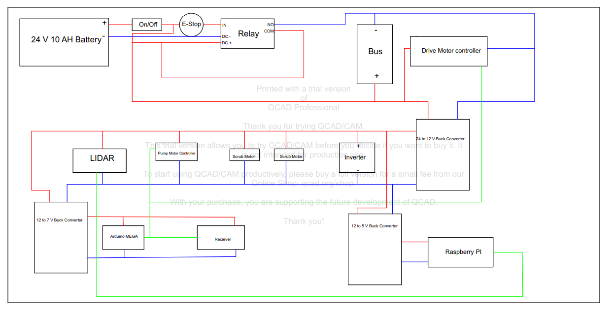
So I came back later on Thursday and wired the motor controller and Arduino MEGA.
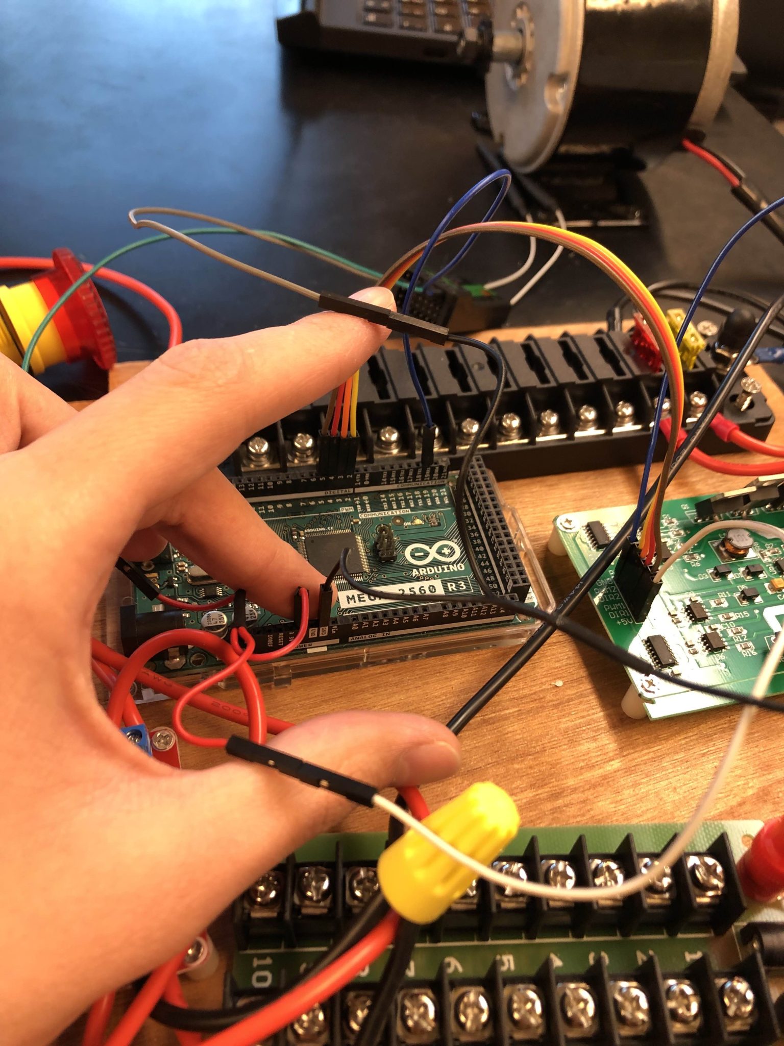
From here I connected the electrical board to a DC voltage supply and tried to run the motor. It worked and the motor ran as it should. Now that, that is working my plan for next week is to continue with wiring the rest of the electrical components, as well as figuring out a way to mount the electrical boards.
Week of September 30 – October 6 2024
This week I worked on our CDR presentation, and our progress report presentation for GM. I also talked with Nick and Donn about our decision on whether to use an inverter or not. The vacuum arrived and its dimensions were not what was given on Amazon, so Nick, Donn, and I started to discuss how this would affect the electrical board size and mounting the components. I worked on the start of the wiring of the Husky-Clean. I only started on the On/Off switch, the E-Stop, the relay, and the 24V rail.
Nick and I also tested what had been wired with a DC voltage supply to make sure it was working as it should. So far all of the wiring is working as expected. Next week I plan to continue work on wiring the robot, continue work on how to mount the electrical board, look into methods to start waterproofing the electrical board based on feedback from GM, and order the inverter.
Week of September 23-29 2024
This week I worked on making the wiring diagram digital. I finished the wiring diagram.
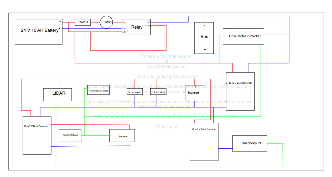
I added all of the parts and the wires connecting them. The red and blue lines are the power wires, and the green lines are the signal connections of each. After doing this I also updated the Gantt chart for the electrical section to show the progress we have completed so far.

I also discussed with Nick how we want mount the electrical components on the shop-vac. We discussed making a board and mounting the components on there and then mounting that on the 80/20 frame for the shop-vac. Finally, we are working on the CDR presentation this Sunday the 29th. Next week I need to work on connecting the electrical components, figuring out how we want to mount them, start mounting the electrical components, and working on the progress report presentation to GM.
Week of September 16-22 2024
This week I worked on the Gantt chart for the electrical sub-team of the Husky-Clean. This finalized when we should be starting each aspect of the electrical parts of the Husky-Clean and when we should be finishing.

I also helped finalize the electrical components we needed to order like the battery, the motor controllers, and the inverter. Most of the parts needed, not just for the electrical system, were ordered this week.
The motor controller we decided on is: Thincol Dual DC Motor Driver Module Board
I was also supposed to meet with Nick and Donn to work on the wiring diagram this week, but I ended up not being able to make it due to a fever. They met and worked on the wiring diagram and then sent it to me to review.
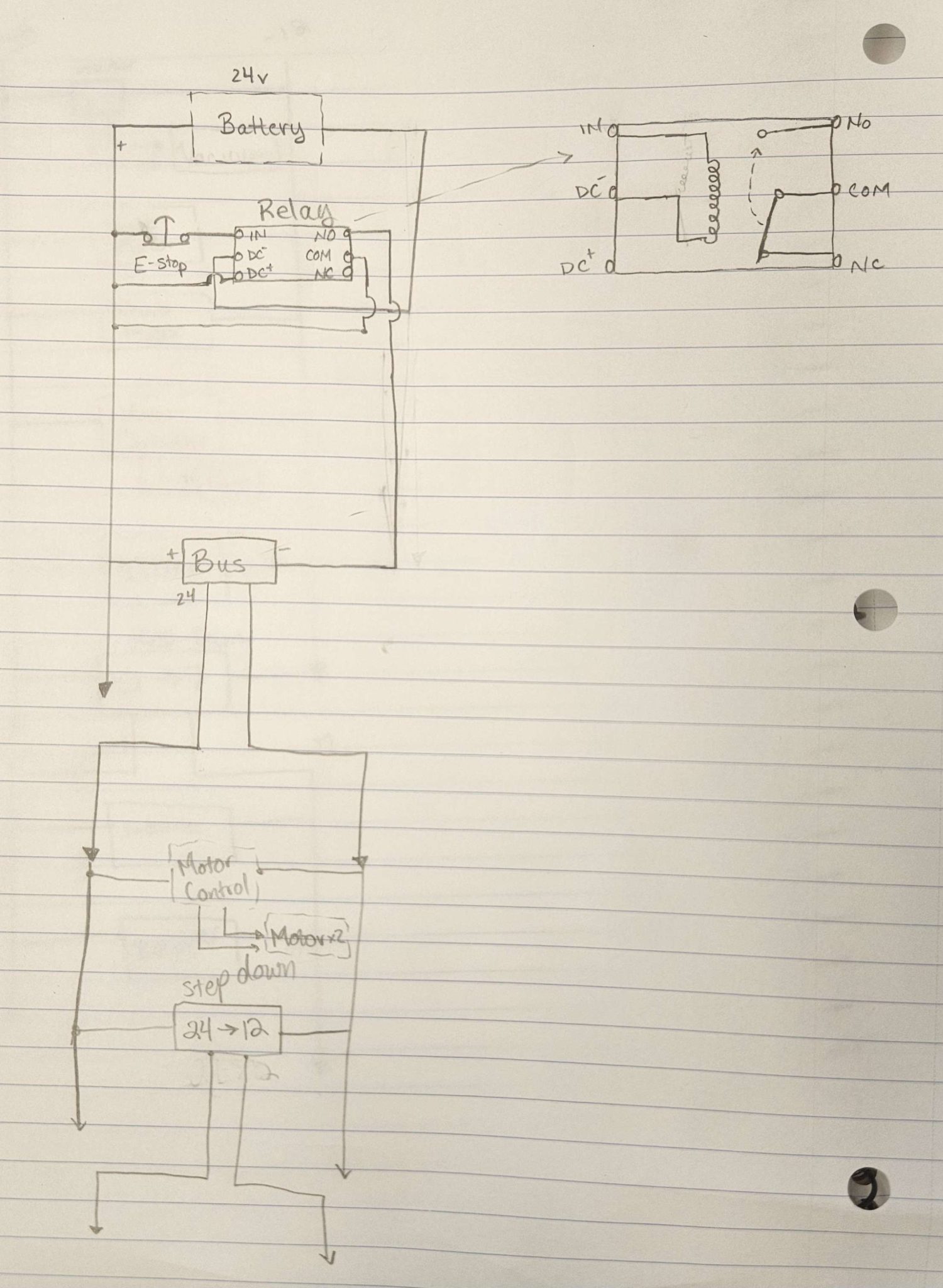
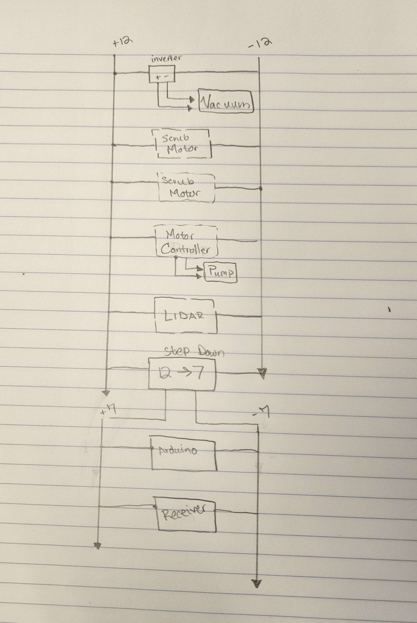
We also heard back from the SICK 10K LIDAR challenge and were informed that we had been accepted into the challenge. Next week my plan is to start making the wiring diagram digital, order any electrical components we still need, and start the assembly of the electrical board with mounts.
Week of September 8-13 2024
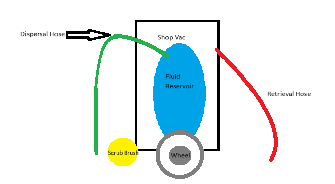
This year I am working on the Husky-Clean project. This is a lab cleaning robot that we are building around a Shop-Vac. I understand that the Husky-Clean will dispense a cleaning solution from a bladder inside the Shop-Vac, and then use scrub brushes to spread the cleaning solution and clean up messes. It will then use the vacuum feature and pick up the mess. I made a very, very basic design of the Husky-Clean from what I understood of the project.
My current work has been focused on the electrical portion of the Husky-Clean. As Grow-Bot is no longer a project we started to cannibalize the electrical system of the Grow-Bot. We will be using the fuse box, the PDP, the Buck Converters, the drive motor controller will be used for the scrub brush motors, and the Arduino MEGA. I have done the battery calcs based on the products that we will most likely be using.
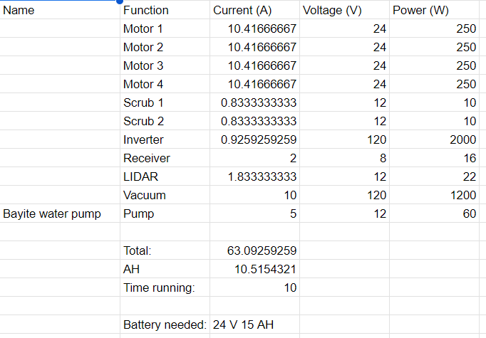
From these calculations we have determined that we will probably need a 24 V DC battery with a 25 AH. I also determined that the motor controllers that I had found earlier in the week to run the drive base motors could not handle a 24 V battery. I made these calculations using these components. The scrub motors and the receiver were components from the Grow-Bot so I took the values from there.
One of the concerns I have is that some of the electrical components like the inverter and the battery will be much too heavy for the Shop-Vac to run. As a group the electrical engineers are meeting to discuss the issue and then in the whole group we are meeting again to also discuss the issue.
Week of April 15-20 2024
This week we met on Thursday the 18th. We finished up the final edits to our report and made some final decisions.
- We decided to go with a 4-wheel design for the drive train next semester
- We discussed having more specific and outlined roles for everyone on the team so it is very clear what everyone contributed to the team
- We want to have our decision making done as soon as possible so we can immediately begin ordering parts and begin testing halfway through the semester.
We are confident in what we have done this semester and decided to work on next semester. The report and OSF repository of our work this semester is now public.
Week of April 8-13 2024
This week we met on Monday the 8th to prepare for the Check Off. We also worked on our final progress presentation for GM. We found a few problems when we were checking the robot which were:
- The motors were wired backwards: That is, the robot drives in the reverse direction as input on the controller (forward/backwards).
- The right motor does not engage when the backward motion is input into the controller.
- One of the motor housings cracked
We then met on Tuesday the 9th for our Check Off. We had printed a new motor mount and installed it before the Check Off. We did all of the functional requirements we wanted and then got the following feedback:
- Next semester, the drive train should be updated completely
- The following semester, we must decide on one of the following paths for the robot
- Further sensor integration
- Autonomous navigation
- A winch/connector for tilling, water distribution, some kind of platform to further expand functionality
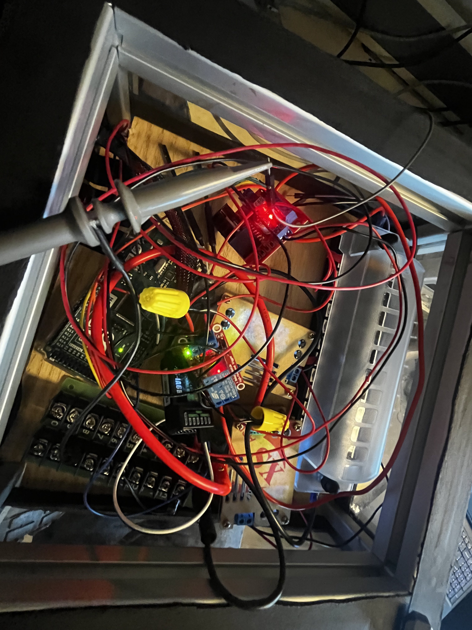
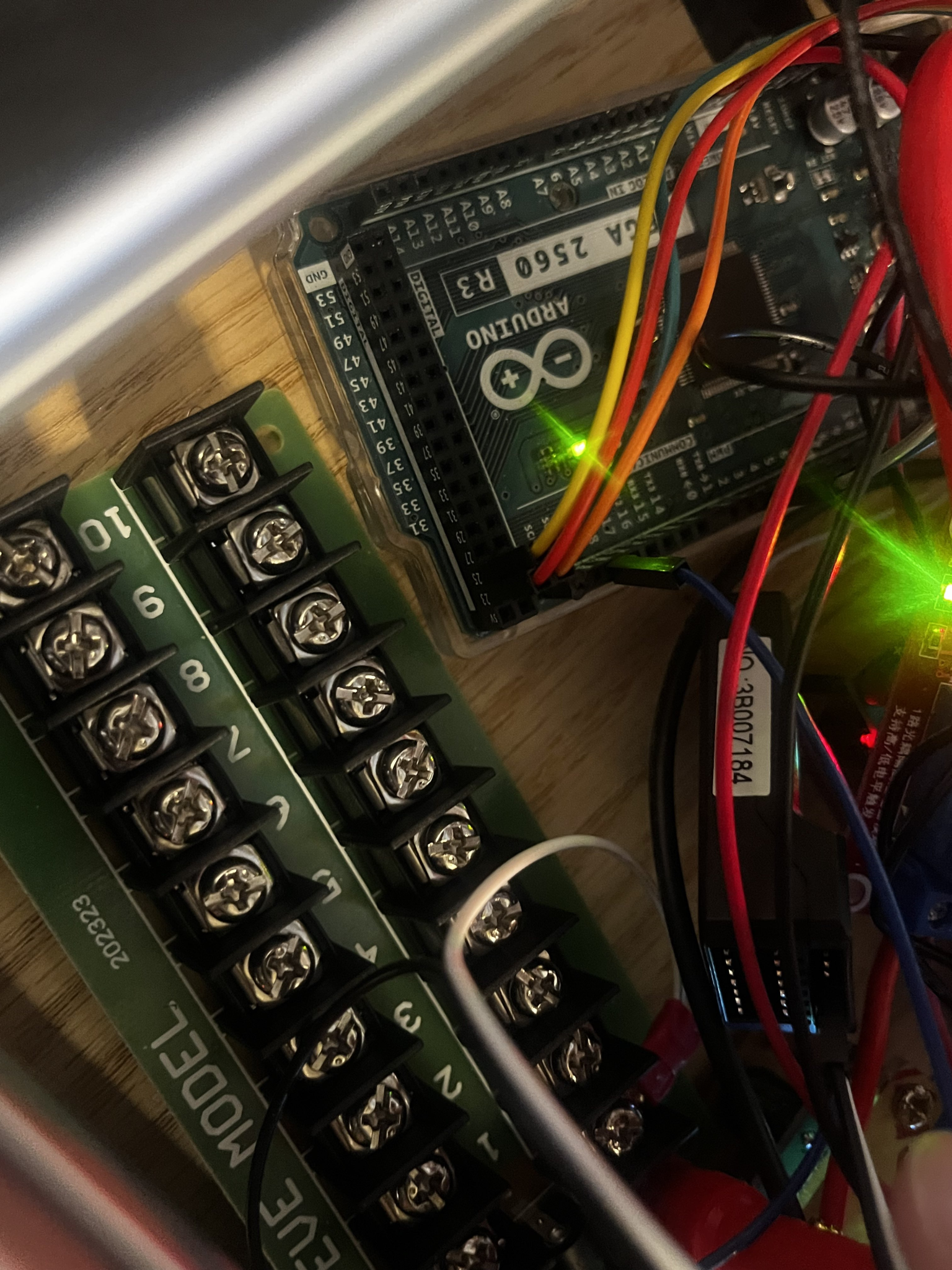
On Wednesday the 10th Hakeem and I met to work on the wiring issue we had discovered on Monday. We checked with an oscilloscope first to make sure the motor controller was getting the right signal. We found that the wires were not transmitting the correct signals. We then checked the code to see where the wires from the motor controller need to go on the Arduino and discovered that we had mis wired some of them.
Then on Thursday the 11th we met with GM to give them our final progress report of the semester.
Week of April 1-6 2024
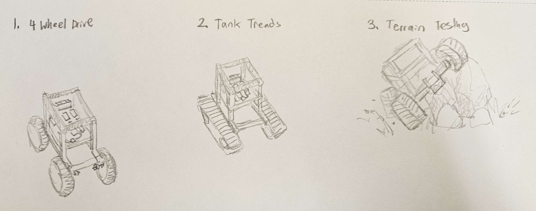
This week we met on Wednesday the 3rd. I soldered new wires to the motor. Nick, Eric, Hakeem and I worked on the project proposal. Nick drew sketches of possible paths for the drivetrain next semester.
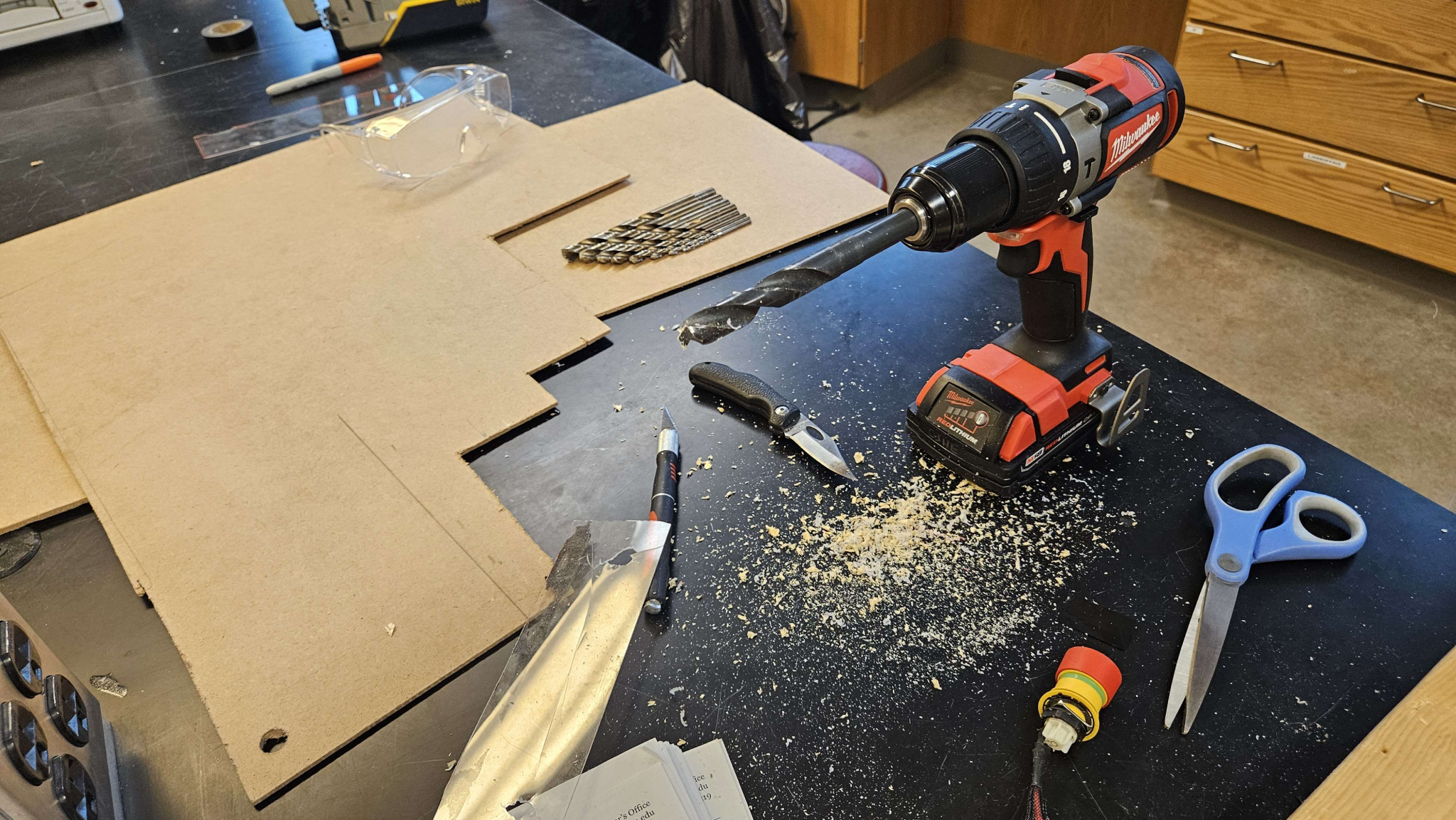
After the project proposal and soldering new wires to the motors we started work on the kill switch. Eric drilled a hole into one of the side panels to mount the kill switch.


We then met on Thursday the 4th. On that day we worked on the Report Draft. We also did videos for our social media post. We all spoke on different parts of the progress done this semester. I spoke on the future paths Grow-Bot is going to take. After this was done we finished wiring the robot. We did this by using wire nuts and connecting the motors to the motor controllers.
We then turned on the robot and tested to make sure it could drive. It could, but there was an issue with the turning. We also tested if the kill switch works and it does.
Week of March 25-30 2024
This week I met with Ben Boelens to learn what I need to do as a Budget Manager for OSHE. We met on Wednesday the 27th. I also met with Nick and Eric to work on wiring the new electrical board on Wednesday. We all followed the diagrams we had drawn to wire the new board.

We detached all components from the electrical box: The breadboard, the Arduino, the motor controller, the FlySky receiver, and all sensors. Then, we secured two buck converters to the Fuse block. One buck converter was wired the Arduino MEGA, and the other was wired to a power rail. The FlySky receiver was then attached to the power rail.
- The gauge of the wire used depended entirely on the kind of connectors that would be secured to the devices. It is possible we may need to modify it later.
- We used a 1A fuse for both the Arduino and the 5V power rail. We are planning on using a higher amperage fuse for the motor controller.
Week of March 18-23 2024
This week I met with Eric and Nick on Wednesday the 20th. I updated the Gantt chart for this semester to show the goals we need to accomplish and when we need to accomplish them by the end of the semester.
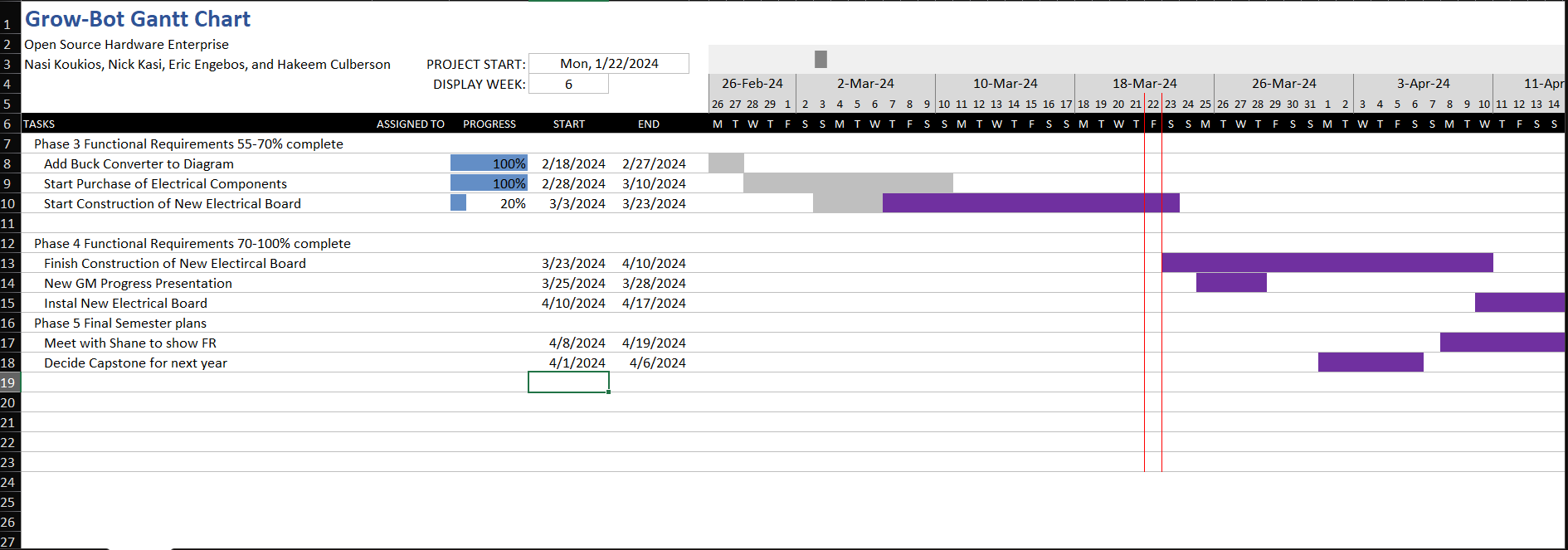
We also decided on what we were going to do for Capstone next year. This will be a new drivetrain that can go over any terrain. We came up with the steps we will need to do as well as anything else we might need. We reached out to Ben Keppers for help with wiring the new electrical board on our robot.
On Thursday the 21st I attended the lab clean up day meeting. Ben also replied to our questions so Nick, Hakeem and I met later that day. I wired the relay, kill switch and fuse block based on a diagram we had made.
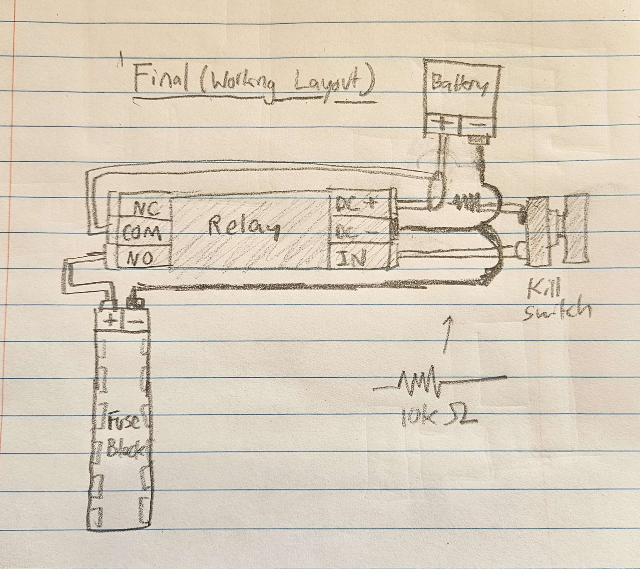
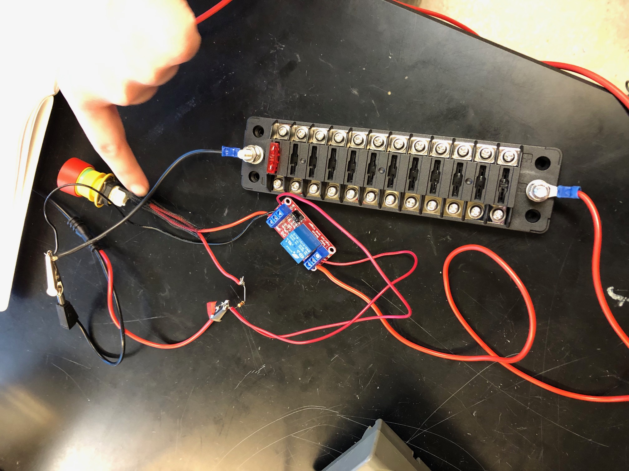
Once the wiring was done we tested the circuit with a 5V from a DC voltage supply.
Week of March 11-16 2024
This week we met on Tuesday the 12th. We worked on our progress report presentation for our sponsors GM. For the report I updated our Gantt chart to show the progress we had completed, and to show that we were still on track for our goals.
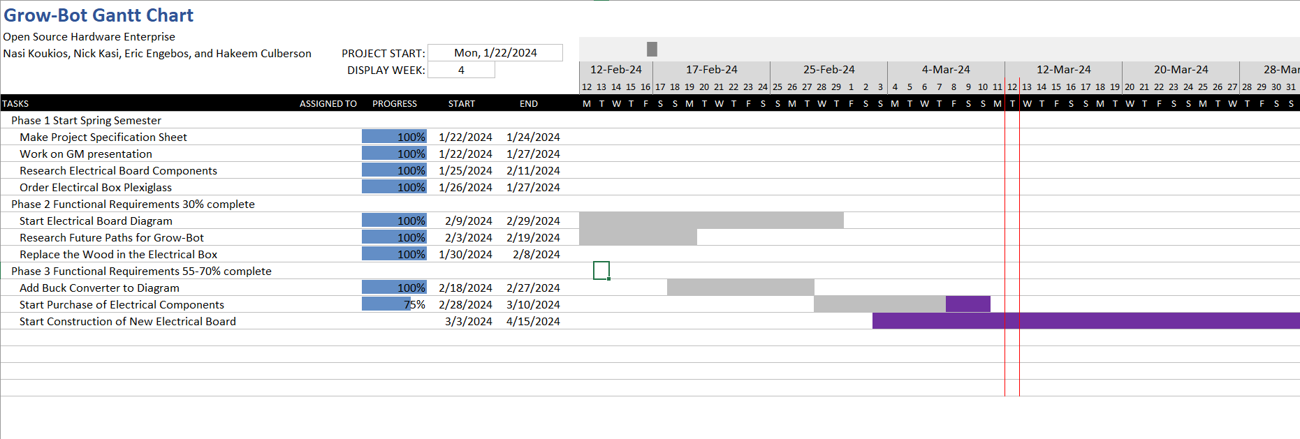
We also ordered the last of the electrical components we need to make the new electrical board. These are the relay and the fuse block.
- 12 line fuse block – This will be the first area of distribution, our 12V line. This allows fuses to be easily replaced, and even accounting for 4 motors and 1 branching 5v line, still leaves plenty of space for future implementation.
- Relay – This is the way we will implement our killswitch into the circuit.
Nick created our QKad file to show the diagram of the new electrical board.
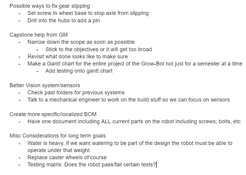
On Thursday the 14th we presented to GM and they gave us the feedback shown below.
Finally on Thursday I made the Project Overview page for Grow-Bot.
Week of March 4-9 2024
This week we met on Tuesday March 5th to discuss Capstone as well as the future of the Grow-Bot with Dr. Oberloier.
We then met on Thursday March 7th. Well there I created a google doc to act as a timeline for future semesters as well as what the Grow-Bot needs to do when it is completed. Nick, Eric and I discussed what we wanted to do for Capstone next year, and came up with two possible paths. We decided to give ourselves some time to think it through and choose what we want to do at a later date. Next Eric, Nick, Hakeem and I tested if the Grow-Bot could drive over an incline. We had some struggles with it but found that it was a good way to test the maximum current of the motors. We found that at best we could get 1 amp. We also looked into two possible fuse boxes for when we start creating the new electrical board.
Possible fuse boxes:
8 Circuit block holder:Amazon.com: WUPP 12 Volt Fuse Block, Waterproof Boat Fuse Panel with LED Warning Indicator Damp-Proof Cover, 6 Circuits with Negative Bus Fuse Box for Car Marine RV Truck DC 12-24V : Automotive
12 Circuit Block holder
Week of February 19-24 2024
This week we ordered the new rails and buck converters on Monday the 19th.
We also presented our CDR on Thursday the 22nd. From there we got feedback on the points shown below.
- Test the current draw from the motors again: In more rough conditions, looking for peaks or spikes, and the “stall” current when the shaft is being stopped forcefully.
- Consider using “slow-blow fuses” to account for peaks.
- Consider what fuses to use for sensors
- Look at the documentation for sensors to make sure that the current does not EXCEED the max current.
- When would a high current happen? Either from a degrading sensor that would have to be replaced anyway, or a short. In this case, fuses do not have to be as precise.
- Relays are the only way to implement kill switches. Look into how to do this for sure.
- Check the current rating of the battery.
- Simulation can be performed in Multisim as long as the images and documentation is available.
Week of February 12-17 2024
On Wednesday the 14th Eric, Hakeem, and I started working on the Critical Design Review Presentation. Eric and I also replaced the wood panels on the side of the electrical box with new plexiglass. We also tested how much current the motor draws and how much current the other electrical components draw. We used a multimeter on the DC amp setting to determine this. For the motors we got between 0.25-0.6 A. The receiver got a value of 0.12 A.
On Thursday the 15th we met with GM to update them on our progress
Week of February 5-10 2024
On Wednesday the 7th the group met to discuss the Critical Design Review and talk about the parts we had researched. We wanted to choose which parts we were going to get. We found a kill switch and fuses in the lab. I made a bill of materials for the parts we have and are going to get.
| Parts | Price | Link |
| Power Distribution Rails | $13.99 | https://www.amazon.com/PCB005-Distribution-Inputs-Outputs-Voltage/dp/B07BC9BV1S?source=ps-sl-shoppingads-lpcontext&ref_=fplfs&psc=1&smid=AUGR43JJM44E6 |
| Buck converter | $16.99 | https://www.amazon.com/Converter-DROK-Regulator-Transformer-Protection/dp/B07FL6PBZF/ref=sr_1_6?crid=1IKD7ZWDABTOW&keywords=Power%2BDistribution%2BBoard%2Bregulators%2B12v%2B5v%2B7v&qid=1707332288&sprefix=power%2Bdistribution%2Bboard%2Bregulators%2B12v%2B5v%2B7v%2Caps%2C101&sr=8-6&th=1 |
| Arduino Screw Terminal Shield | $5.95 | https://www.digikey.com/en/products/detail/adafruit-industries-llc/3173/7794998?utm_adgroup=&utm_source=google&utm_medium=cpc&utm_campaign=PMax%20Shopping_Product_Low%20ROAS%20Categories&utm_term=&utm_content=&utm_id=go_cmp-20243063506_adg-_ad-__dev-c_ext-_prd-7794998_sig-CjwKCAiA8YyuBhBSEiwA5R3-Ew3cLz1z41JRu97HpXS6ZF6R8nPFSsTs5I42ZSimn1pkb3l4Egor2RoCbWsQAvD_BwE&gad_source=1&gclid=CjwKCAiA8YyuBhBSEiwA5R3-Ew3cLz1z41JRu97HpXS6ZF6R8nPFSsTs5I42ZSimn1pkb3l4Egor2RoCbWsQAvD_BwE |
| Kill Switch | $51.20 | https://www.digikey.com/en/products/detail/eao/61-6441-4047/8735380 |
| Fuses | $7.34 | https://www.grainger.com/product/1DJ54?gucid=N:N:PS:Paid:GGL:CSM-2296:9JMEDM:20500731&gad_source=1&gclid=CjwKCAiA8YyuBhBSEiwA5R3-E8grk8uXHY472quuZv_IGAaI-tbdvO_9Tt5oWw6SU1QVD90mRIzX0hoCTywQAvD_BwE&gclsrc=aw.ds |
Nick also drew a basic diagram for the wiring of the new electrical board. However, Hakeem found that the fuses we have were too high so he started looking for automotive fuses.
Week of January 29 – February 3 2024
Nick, Eric and I met on Tuesday January 30th. We discussed researching a power distribution panel with a fuses or circuit breakers for the new electrical board. We worked together to finalize the presentation for GM by updating our budget information, what we might need help with, and any electrical updates we made to the Grow-Bot. We also discussed looking into a new motor controller, and a new battery. Also looking at RC vehicles for help when designing an electrical board. We decided to use the rest of week 4 and week 5 to research the components and then in week 6 we will meet and decide which components to order.
On Thursday February 1st the Grow-Bot team presented to our sponsors to update them on our progress over the past 2 weeks. We let them know about ordering the plexiglass, and starting to design the new electrical board. We also asked them for any advice they could give on where to order electrical components, how we should organize our future plans for Grow-Bot, and any other advice they had. They suggested the following websites to order components from.
https://www.digikey.com/en/supplier-centers/jst
They also suggested that we do the following.
Week of January 22-26 2024
I worked on the progress report presentation for GM with Eric, Nick and Hakeem on Thursday the 25th.
We also talked about starting the diagram for the new board and Eric planned to order the new plexiglass to replace the wood on the side of the electrical box. I also worked on the Gantt chart for the Grow-Bot for this semester.
Week of November 27-December 2 2023
This week I met with Nick and Eric on Monday to work on the lab report and to test how the robot drives. Eric attached the caster wheels to the back of the robot. I used the Flysky while Eric recorded a video and Nick had his laptop connected to the Grow-Bot. We got it to successfully move backwards and turn in one direction. However, an issue with turning in the other direction and going forward occurred. We realized that one of the front wheel mounts was cracked and was making the gears not connect. Nick, Eric and I also started work on the final report and we got through most of it.
On Thursday, we met again and Eric had 3-D printed a new front wheel mount, while Nick started our EMI presentation for our sponsor GM. Eric and I helped out on the power point. Later in the day we also presented our progress, budget, and future plans to GM.
On Friday, we met for a final time this week to attach the new front wheel mount and work on the lab report. Eric attached the new wheel mount to the robot, and we again tested how well the robot moved. I again used the Flysky while Eric recorded a video and Nick attached his laptop to make sure there were no errors with any movement. Also we tested the water resistant cover and recorded pouring water on the cover. We mostly finalized the report, but a few adjustments need to be added. I also organized some of the wires in the electrical box on the robot with the use of electrical tape.
Week of November 13-18 2023
This week I met with Nick on Wednesday. He worked on the schematic, while I found some more L-brackets to further secure the water resistant cover. After this Nick, Eric and I met on Thursday. We talked about what else we had to do, to meet the functional requirements we had set. We also talked about what we want to do next semester, and how to meet with our sponsor to update them on our progress.
Week of November 6-11 2023
This week I met with Nick on Monday while he worked on the schematic. There was not anything for me to do so I left. On Thursday I met with Eric and Nick, and Eric told us that his computer was repaired and he was going to be printing the wheel mounts over the weekend. Eric also told us that the L-brackets that we needed to further secure the water resistant cover had arrived. We decided that we would meet next week to attach the wheel mounts and figure out anything else we need to do.
Week of October 30-November 4 2023
There was not a lot that happened this week for the Grow-Bot. We met on Thursday to discuss what we needed to do in the next few weeks. Eric and I talked about the 3D printing that needed to be done and how to further secure the water resistant cover. Nick worked on the schematic for the robot during the week.
Week of October 23-28 2023
This week Eric, Nick and I met on Tuesday to try to figure out how to fix the FlySky controller. Eric detached the broken front wheel mount, and I removed the electrical tape from the soldered wires. I then tested the motor windings and the power of the motors to see if they were broken. Once we had tested the components Eric noticed that one of the pins on the Arduino for the motors was disconnected. Eric started to take one of the back wheel mounts and move it to the front wheel , but Nick asked him to help with the code for the FlySky, so I finished putting the front wheel into a new wheel mount. Eric and Nick were able to figure out what was wrong in the code and made it so that the controller could move the wheels.
Week of October 16-21 2023
This week we met on Monday to discuss what we wanted to focus on for the rest of the semester and what we each would be doing. Eric spoke about finishing the water resistant cover, and 3D printing what we need to attach the back wheels and fix the front wheel. Nick and I worked on trying to figure out how to get the FlySky controller to work for the robot. We were unable to get it to work on Monday, but Nick figured out that the problem is with the motors not the code.
Week of October 9-14 2023
This week we presented our Critical Design Review on Tuesday. Before the presentation Nick and I did a practice presentation on the slides we were going to present. We all also worked on the slide show before the presentation.
On Thursday, I met with Nick to try to figure out why the FlySky controller was not working as intended. We also checked to see if the new set of back wheels would work for the robot and they will. They are 4 inch swivel wheels. We are now trying to come up with a way to attach them to the robot. Once that was done we focused on the controller. We figured out that if the auto switch is on when the robot is turned on the wheels and gears will go forward until the robot connects to the FlySky. The FlySky controller could not get the gears to turn no matter the edits we made in the code. It was decided that Nick would reach out to the Sandhal twins as they were the ones who wrote the code we are using to try to figure out where we are going wrong.
Week of October 2-7 2023
On Monday I met with Eric Engebos and Nick Kasi again. I helped Eric attach the water resistant cover to the electrical box.
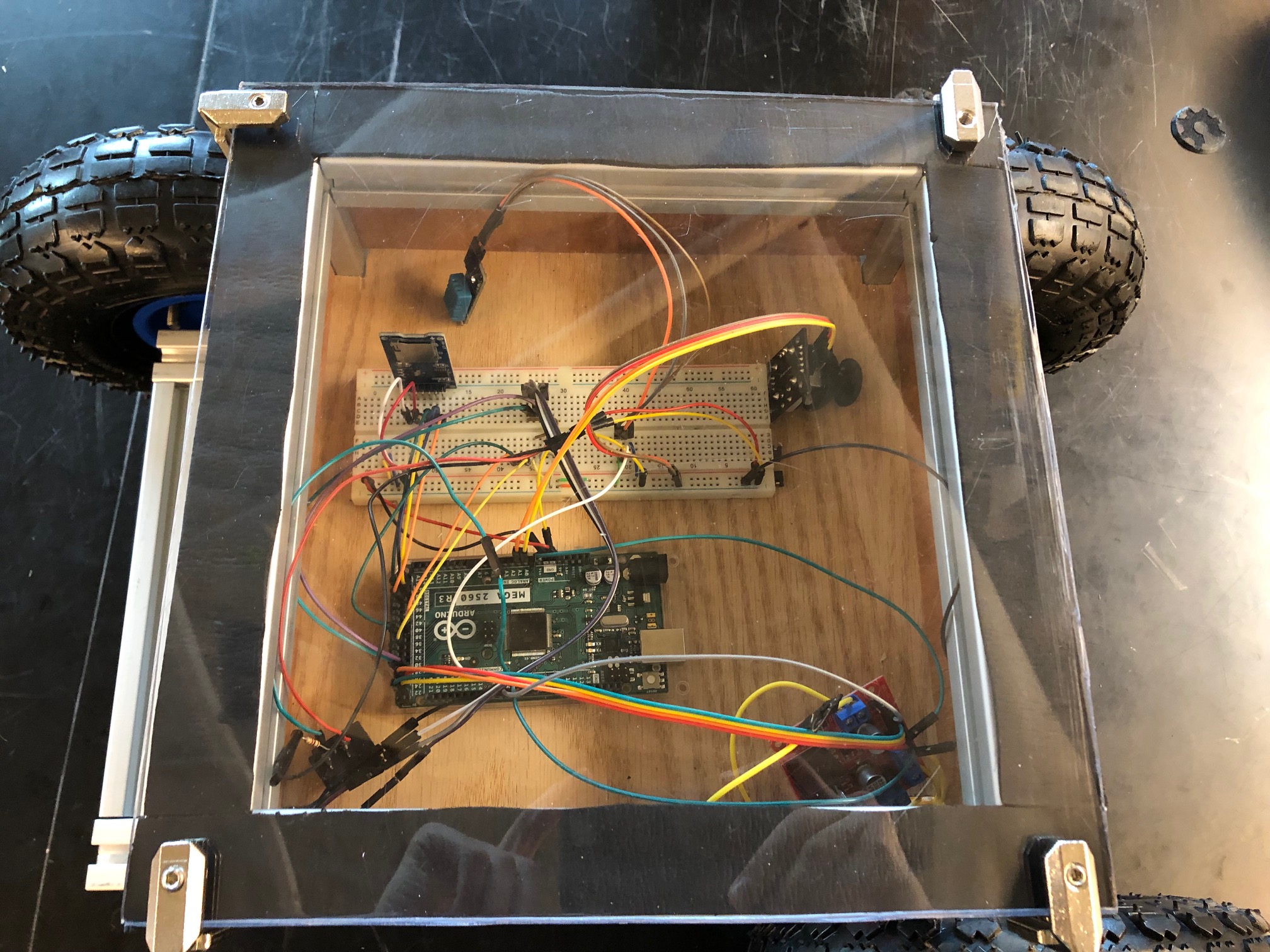
After Eric and I finished attaching the cover we moved onto helping Nick who was trying to get the FlySky controller connected to the receiver while, the receiver was connected to the robot. With a warning that there was no battery every time we tried to connect. We fixed this problem by changing the settings for the external and internal sensors on the controller. After we got the controller connected we tried to run the code to see if the robot would respond to the FlySky controller. Once we activated the code the wheels would turn in reverse and once the FlySky controller was connected all movement would stop. When we moved the right joystick on the controller the motors would barely turn. Nick and I tried to replace the battery in case that was the problem, but the power switch got disconnected when we tried to rerun the code.
On Tuesday I came into the workspace and fixed the power switch by soldering the wire that had come loose. This was all the work I know of that we did for the Grow-Bot this week.
Week of September 25-30 2023
During this week I met with Eric Engebos and Nick Kasi on Monday the 25. While there we looked at the new back wheels we got for the robot and determined that they would not work as intended. Due to this we decided to get a different set of back wheels. While Eric cut a new plexiglass cover for the electrical box on the robot, Nick and I worked on our Critical Design Review power point presentation. We also took pictures and videos of the robot turning on and of the gears moving while using the joystick currently attached to the robot. This is all the work I have done for this week, but I know that Eric worked on cutting some foam to attach the new plexiglass cover and Nick worked to get the FlySky controller connected to the robot.
Week of September 18-23 2023
During this week I met with Eric Engebos on Monday and secured the battery base to the Grow-Bot. We also discussed two possible plans to make the electrical box water resistant. To do this we planned to put a sheet of plexiglass over the electrical box, but we were trying to come up with the best way to secure it. Next we spoke of a way to improve the gears on the robot so we could improve the movement of the robot. For Monday we also came up with a list of parts we needed to order.
On Tuesday Nick Kasi and I met with Nick and Adam Sandhal to get the robot turned on and moving. This was because the bot was disassembled after last semester and we did not know what was needed to make it functional. Nick and Adam also taught us about the code. We also learned that we will need a new FlySky controller for the bot.
On Thursday during the cleaning of the lab we found out the Quadcopter project was scrapped and that instead of ordering a new FlySky controller we could use the one the quadcopter had. That was the last of the work we did for this week.
