
9/22/2023
Recap
- Went through documentation for the YOLO object detection algorithm
- Installed YOLO on the raspberry pi
- Received USB camera
- Found this article by propelland on how to record using a USB camera on a raspberry pi
To do
- Integrate USB camera using propelland article
- Train YOLO on water bottles
9/29/2023
Recap
- Attempted to use propelland article, but it was made for a video stream and not single captures as this project needs
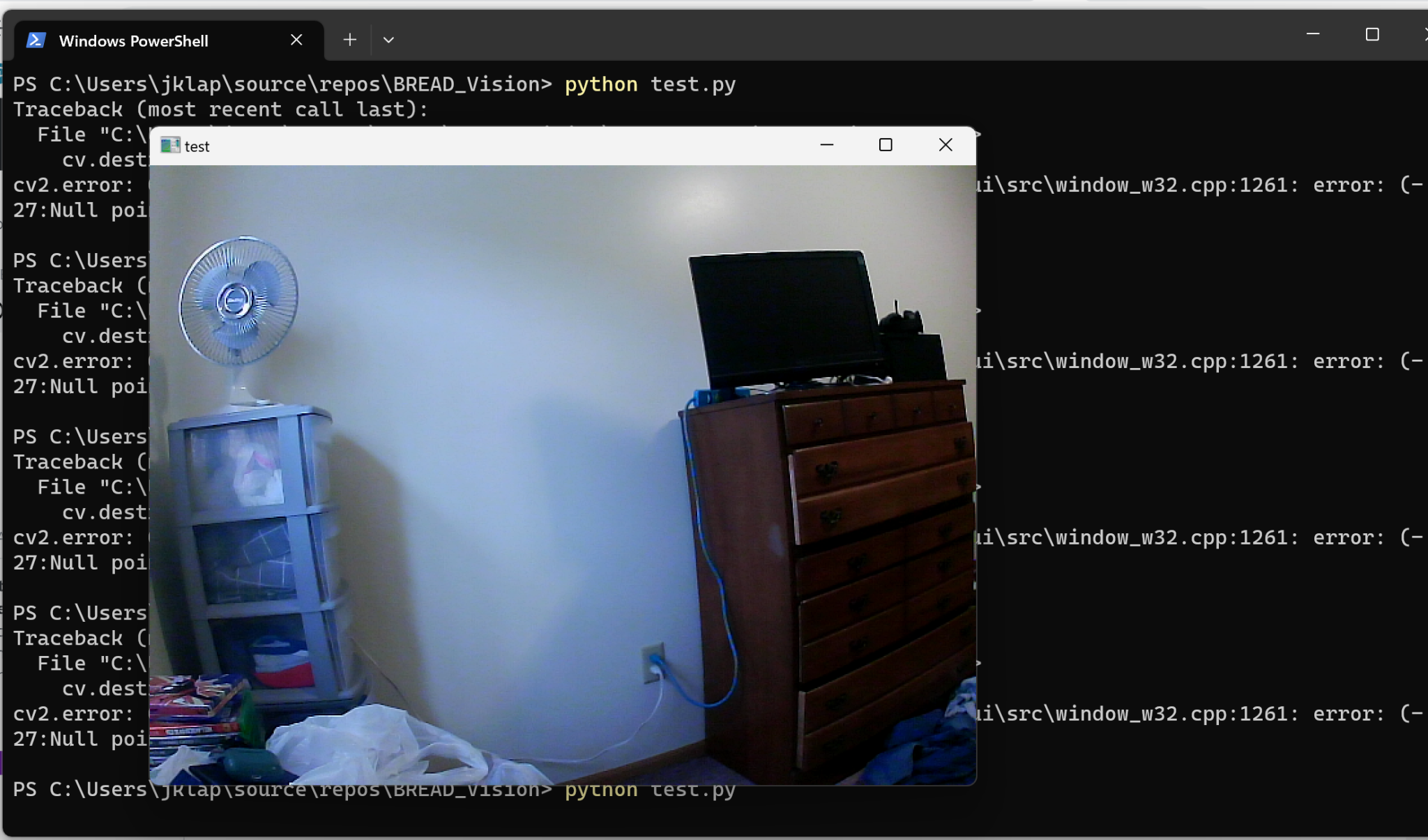
- Was able to capture images using a USB camera using OpenCV VideoCapture() method
To do
- Continue work on training YOLO
- Integrate detection software on USB images
10/07/2023
Recap
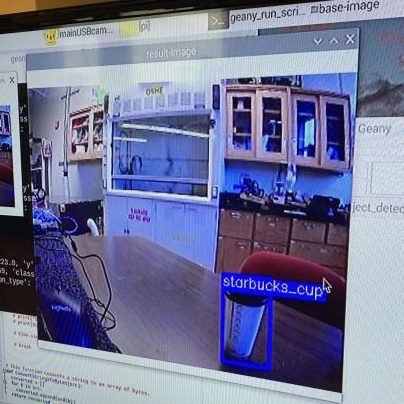
- Trained YOLO model on medium Starbucks cups using Roboflow following this article
- Uploaded trained model weights to the Pi
- Troubleshooted YOLO install on the Pi. Had an error with keyboard shortcut APIs blocking YOLO import.
- Got software for USB camera to work on my laptop and try to perform detection on images
To do
- Move USB camera to Pi and confirm that detection software works on captured images
- Continue troubleshooting YOLO and get detection software finished
10/22/2023
Recap
- Got YOLO running on the Pi and working on uploaded images
- Created software using Roboflow to analyze captures while the Pi took them with a USB camera
- Very slow due to multiple file saves, may be able to optimize
- Moved USB camera software to Pi and was able to get it running with a presumably correct output
To do
- Confirm that USB camera is configured properly for current code
- Optimize Object Detection code
- Test to confirm that defects do not get recognized by the camera
10/27/2023
Recap
- Added support for the pi camera in the object detection
- Much faster than USB camera analysis, but still somewhat behind camera feed
- Printed new camera mount
- Performed some testing with different lenses and positions for detection accuracy
- Some issues with low contrast backgrounds, but for our purposes this should be fine as we want to have a controlled, calibrated environment for testing our objects
To do
- Test defect detection and modify tolerances
- Add I2C communication to the BREAD Loaf
11/05/2023
Recap
- Tested dent detection using object detection software
- Modified confidence tolerance within code to try to get deformations to be recognized
- Too high tolerance for missing parts, could not recognize when a lid was missing
- Retrained model with a more strict and consistent setup
- Will hopefully be stricter when trying to recognize the cup as it has less information about it in different positions
To do
- Test new model on dented cups
- Add I2C communication to the BREAD Loaf
11/19/2023
Recap
- Retested dent detection using object detection software
- Trained in one position while rotating cup between pictures
- Gave much tighter tolerance for cup recognition, missing lid or dents drop about 5% confidence consistently
- Worked through corruption issues
- Accidently cut power to the pi while writing to the hard drive
- Corrupted config files and had to reinstall libcamera and rewrite some files
- Caused Picamera to not be recognized
- Finished support for USB camera by adding separate Color Detection file with modified image dimensions
- Added support for using both USB camera and Picamera at the same time
- Can be modified to use different types of analysis on each camera
To do
- Work on I2C communication to the BREAD Loaf
- Begin drafting final report
12/08/2023
Recap
- Worked through issues with Roboflow
- Limited to 1000 API calls per month
- Due to being offline, updated all at once at the start of December and prevented usage of our weights
- Retrained using same images and uploaded new model
- Added I2C communication
- Raspberry Pi sends what test is being run with a true or false to indicate a pass or fail
- Arduino processes this signal to do various things
To do
- Finish report
- Plan for next semester
1/27/2024
New Project: BREAD DAQ
This semester I am starting work on a new project. I will be working towards making a DAQ device for the larger BREAD project. The goal is to have an Arduino read a sensor voltage and convert it to useful data. The Arduino will display this on an LCD screen as well as save this with time data to an SD card.
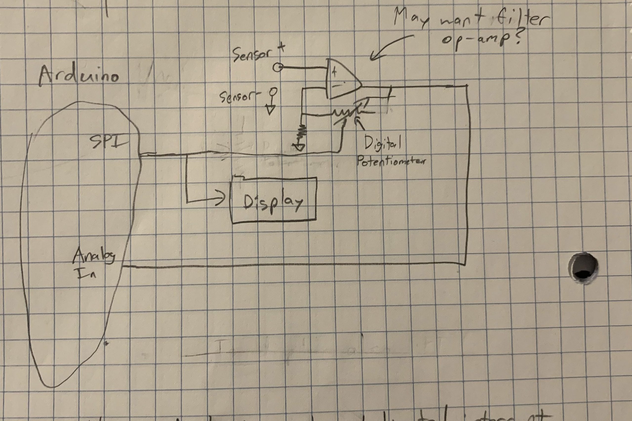
To properly read the voltage, the sensor’s output will need to be amplified to create a more readable voltage. This will be done using an op-amp and digital potentiometer to change the amount of amplification depending on the sensor the device is set to read from. Below is a sketch of what this may look like on the Arduino.
To do
- Start programming the Arduino
- Will focus on being able to read a voltage and then add the ability for it to convert that voltage to a usable data value. This conversion will be easily modifiable to allow for different sensors to be used
- If parts come in, begin breadboarding circuit for controlling amplifier and reading in a sensor voltage
Concerns
- Parts will not arrive, so breadboarding and planning the circuit may not be able to start
- If this occurs, more coding work will be done, likely preparing the display on the LCD screen to display the reading from the sensor
2/3/24
Recap
- Planned how our code should look; we want each type of sensor to have it’s own function to convert a voltage to data and format that data in a String. The function being used will be determined by a variable that can be set in the code. Eventually, we would like this to be changeable using push buttons.
- Began writing some of this code
- I focused on the code for reading a voltage from the Arduino and sending it to the proper function to handle it.
- Brett soldered the LCD screen and wrote some test code to begin writing to it
To-do
- Breadboard a test circuit once parts come in
- Continue coding
- Still need code for each sensor to convert the voltage to data
Concerns
- Parts will still not come in. This may prevent us from having time to get an initial design for our PCB board before midsemester
- Winter Carnival will be too busy to get a lot of work done. This is being planned around and should not affect the project overall
2/10/24
Device Operation Flow
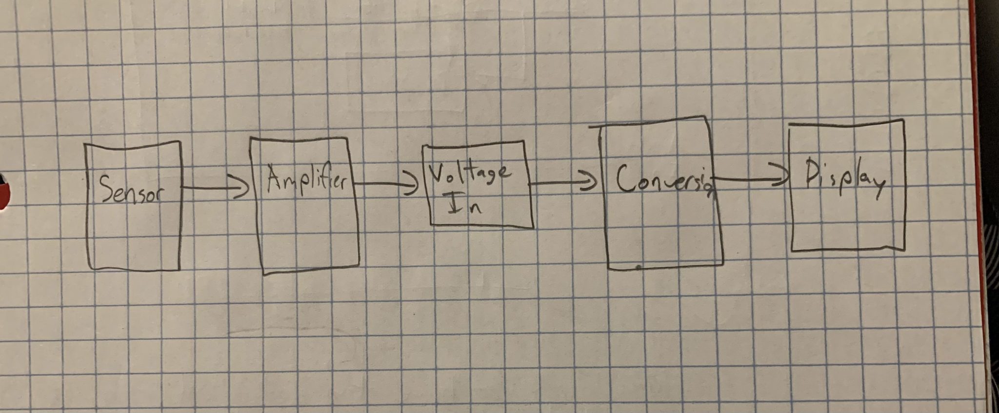
The main flow of the device will be reading in a sensor voltage, amplifying it by some amount, and then reading that voltage and converting it to usable data that can be displayed on the LCD screen. The amplification level and conversion formulas will change with the device state to match the correct levels for the sensor being used. This state will be controlled either through a change in the code or by using buttons built into the slice.
Recap
- Added some code for converting voltage read to usable data
- Still waiting on parts
To-do
- Breadboard a test circuit
- Continue coding
Concerns
- Parts will still not come in. This will certainly prevent us from having time to get a functional initial design for our PCB board before midsemester, however a theoretical design is in progress
2/17/24
Recap
- Parts came in, so breadboarding was able to begin
- Have LCD Screen able to display a voltage read by an Arduino
- Have a noninverting op-amp amplifier setup using the digital potentiometer, need to find correct amplification amount
To-do
- Test op-amp circuit
- Found that amplification being done is not consistent over the voltage range that we need, may need to modify circuit or op-amp to prevent errors
- Will look into adding ways to add bias voltage to get a cleaner input
- Finish PCB board design and order
- Some progress already made, but it cannot be completed until there is a working breadboard prototype
Concerns
- The op-amp that we have is not accurate enough or the amplification method we are using is wrong
- The sensor may have a lot of noise so a filter will be necessary
2/24/24
Recap
- Tested op-amp circuit to find proper amplification
- Having some error with low voltage inputs being amplified more than expected. When set up as a noninverting op-amp with 181 V/V amplification, were getting about 500 V/V amplification to a 10 mV input
- Not sure how to fix this error, will be looking into different op-amp configurations and error correction methods over break
- Decided that we will add a second sensor terminal and make each terminal capable of reading a resistance based sensor
- Will use a voltage divider circuit by applying 5 V across the terminal that leads to the sensor and back to a built in resistor
- Will have a physical switch between amplification and voltage division
To-do
- Find ways to set up op-amp to get amplification required using a potentiometer
- Finish PCB board design
- Add code for reading from a photoresistor
3/9/24
Recap
- We are changing our design from amplifying a voltage ourselves to using a more precise ADC
- Could not find proper fix to our op-amp problem
- Found this chip that has 24 bits of precision and has been shown to work on thermocouples before
- Uses Sigma Delta ADC to get more precise readings
- Does not automatically convert data, making it useful for more sensors than just thermocouples
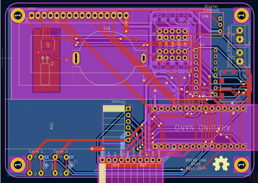
- Finalized and ordered our circuit board
- Has two terminals for voltage divider circuits and an array of resistors that can be chosen from to read resistive sensors
- Will use the ADC chip input for voltage sensors
- Finished code for reading a voltage divider circuit
To-do
- Edit code to use ADC chip
- Code interrupts for changing the type of sensor being used
- Write code for storing data to an SD card
Concerns
- Storing data in a database-convertible way will be difficult
3/16/24

Recap
- Worked on code while waiting for the boards and parts to come in
- Shown above is the interrupt code for the buttons that were added to the board. One will change the type of sensor being used, the other will change the output being used for the display
- Also began converting Thermocouple code to code that is usable with the ADC chip we selected
To-do
- Finish code for calculating values from the ADC chip
- Should be mostly the same code, but will use AD7193 specific functions for reading
- Solder PCB board
- Need to get our parts in first
Concerns
- Nothing beside waiting for parts, but there should be plenty of time for them to come in
3/23/24
Recap
- Soldered and tested our PCB board
- Found some issues with the SD card wiring. The MISO pin was wired through our level shifter chip incorrectly, we have the receiver pin on the Arduino going through the gate towards the transmitter pin on the SD card. This causes data to be unable to be passed back to the Arduino. We also accidentally left the 5v supply instead of changing to the 3.3v supply.
- These issues will be fixed for the board release, but for now are not changeable. We will work around this by using the 5v supply for testing and wiring around the level shifter chip. This is not ideal long term, but will work for getting a working board finished this semester.
- We also used the incorrect pin headers for our terminal blocks, but we found junctions that fit and can be used instead.
- Tested the AD7193 chip
- I had some issues getting the chip to run the example code on Arduino. Ultimately it was several wiring mistakes of not connecting the proper voltages. Once this issue was resolved, I was able to get a reading from the chip.
To-do
- Integrate and modify the example code for our code
- Continue testing the PCB board
Concerns
- There is some other issue with the board that we overlooked and cannot fix. I don’t believe this is the case but it is possible.
- Using the 5v supply for the SD card will break something. This would likely be the SD card or the Nano, but nothing too bad should happen in the short term.
3/30/24
Recap
- Adapted the example thermocouple code into our code
- Were able to get a reading that became formatted and displayed on the screen
- Need to test for accuracy, but is otherwise working
- Continued testing the PCB board
- Found no further issues with the board, so we can begin working on a redesign to be uploaded at the end of the semester
- Did have issues with the IC chip we were using for the real time clock. The oscillator would not spin properly. This may have been caused by the board or a bad chip, but we are not sure. Are currently using a breakout board with a different real time clock so that we will be able to test the SD code.
To-do
- Finish code for reading from a photoresistor
- Should just be a simple voltage divider done using the Arduino. The display code will be the same as for the thermocouple.
- Write code for formatting data before writing to the SD card
- We want to store it in a way that it will be easily convertible to a SQL server
Concerns
- Unfortunately we will not be able to order a new PCB board to fix the problems we have. We are able to work around them for now, but it is a shame that it cannot be fully finished this semester.
4/06/24
Recap
- Continued code for writing to an SD card
- Writes time stamp and then data
- Currently missing type of sensor and units, but I am having issues with writing Strings and did not have time this week to work through it
- Added code support for multiple devices
- Loops through available channels on the board and reads them if they are set as active. The sensor being currently displayed on the DAQ is set as a global variable and can be set by a button press
- For some unknown reason I needed to add a duplicate of this loop within the main code. As far as I can tell it is due to the SD write and the read calls not agreeing with each other causing some code compilation issue. I will likely not investigate this because I will run out of time, but will update if the issue is discovered.
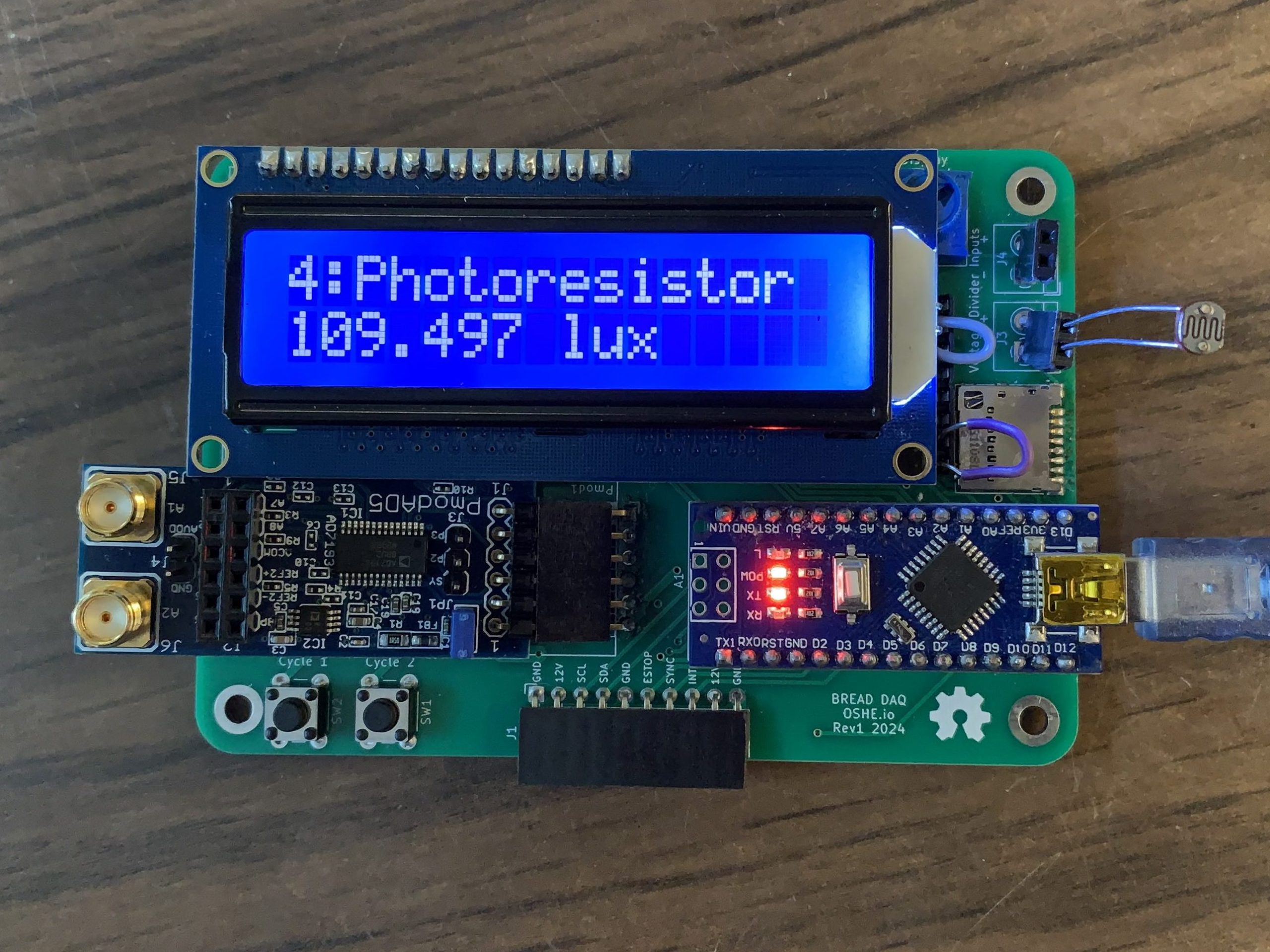
- Finished photoresistor code
- Need to manually change which resistor is being used in the code
To-do
- Test code for reading from a photoresistor
- Write code for translating SD card data
- Will store it as a CSV and then translate it into an SQL database
Concerns
- Some other weird issues may come up with multiple devices.
- Reading a sensor and writing to the SD card takes a good amount of time. Currently may be due to delay() statements but I am not sure if we will have performance issues if they are removed
4/06/24
Recap
- Debugged Photoresistor code
- I did some math incorrectly causing it to output a 0 every time.
- After fixing it, everything worked properly
- Translation code was created and tested. See Brett Hildebrand’s worklog for more details
To-do
- Write reports and documentation
- Test accuracy and get characterization data
Concerns
- Our system may be somewhat inaccurate and we cannot fix it at this point
4/20/24
Recap
- Did temperature testing
- Used a known-good temperature sensor to check values against the DAQ
- Blew a heat gun on both to check if temperatures matched
- Not a close match, but the sensor being used had much more surface to heat. It is possible that our DAQ works properly but it is difficult to tell without a temperature-controlled environment to do testing in
- Finished writing the Report
To-do
- Further testing for accuracy and making adjustments to address the lack of accuracy
9/13/2024
New Project: BREAD CAN Integration
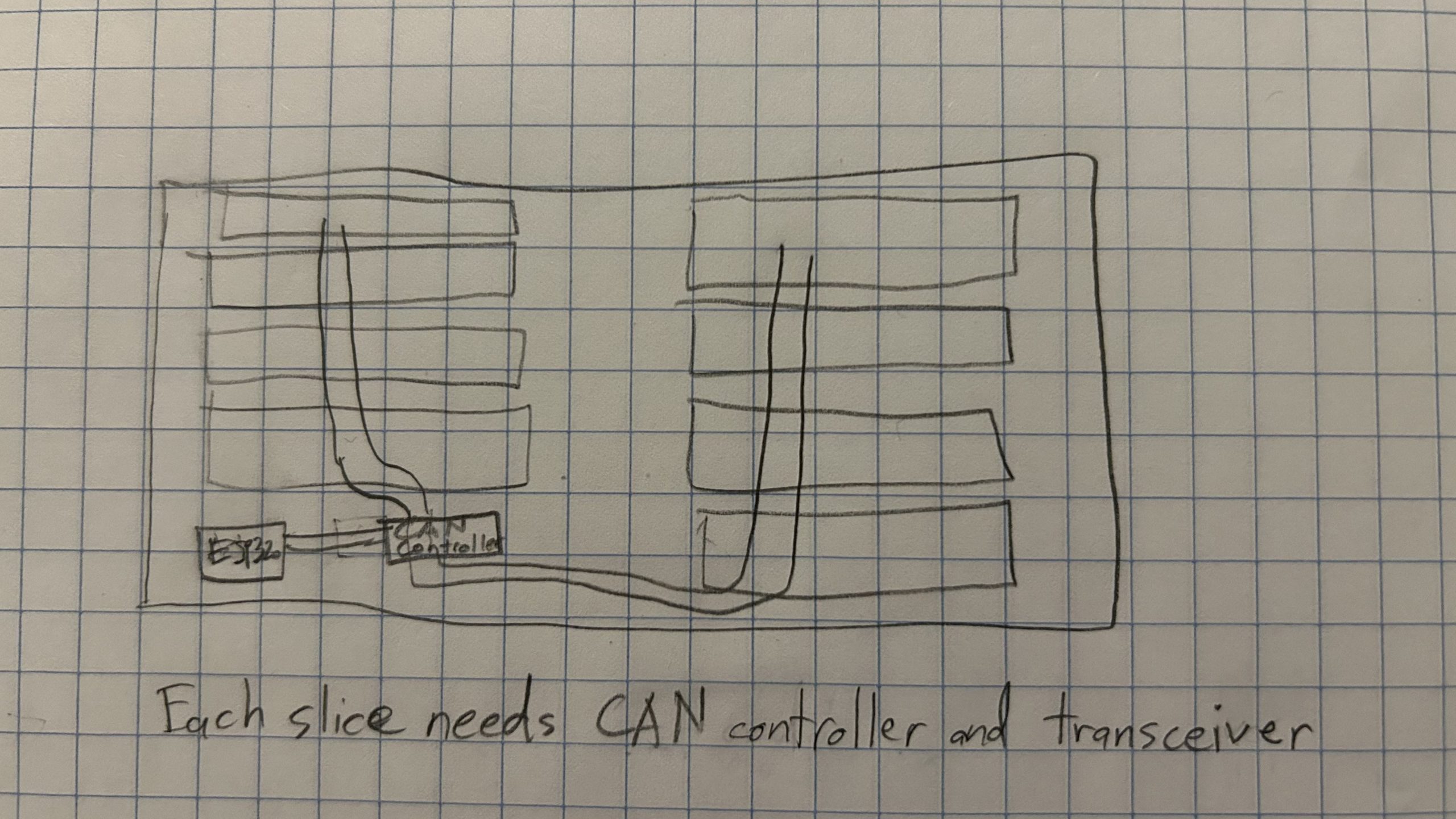
This semester I am shifting my focus on BREAD from new slices to board communication. I will be working towards integrating CAN communication onto the LOAF and previous slices, such as Vision and DAQ. Previous communication between slices has been done using I2C, but has run into problems with different devices wanting to be the master of the bus such as Raspberry Pis. Switching to CAN will make it easier to add devices such as Pis and ESP32s. It will also help facilitate peer-to-peer communication, rather than relying on a master in between each slice.
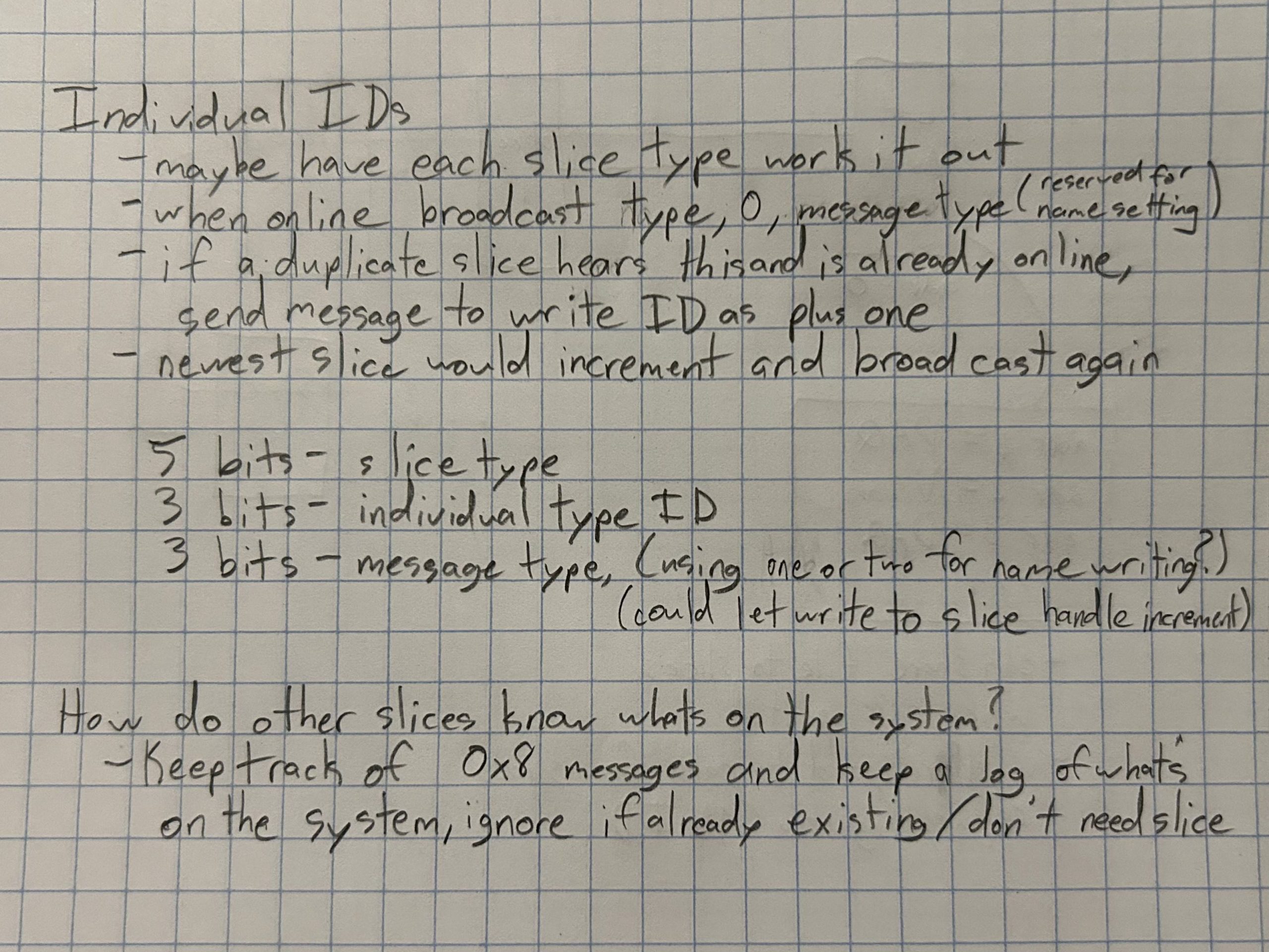
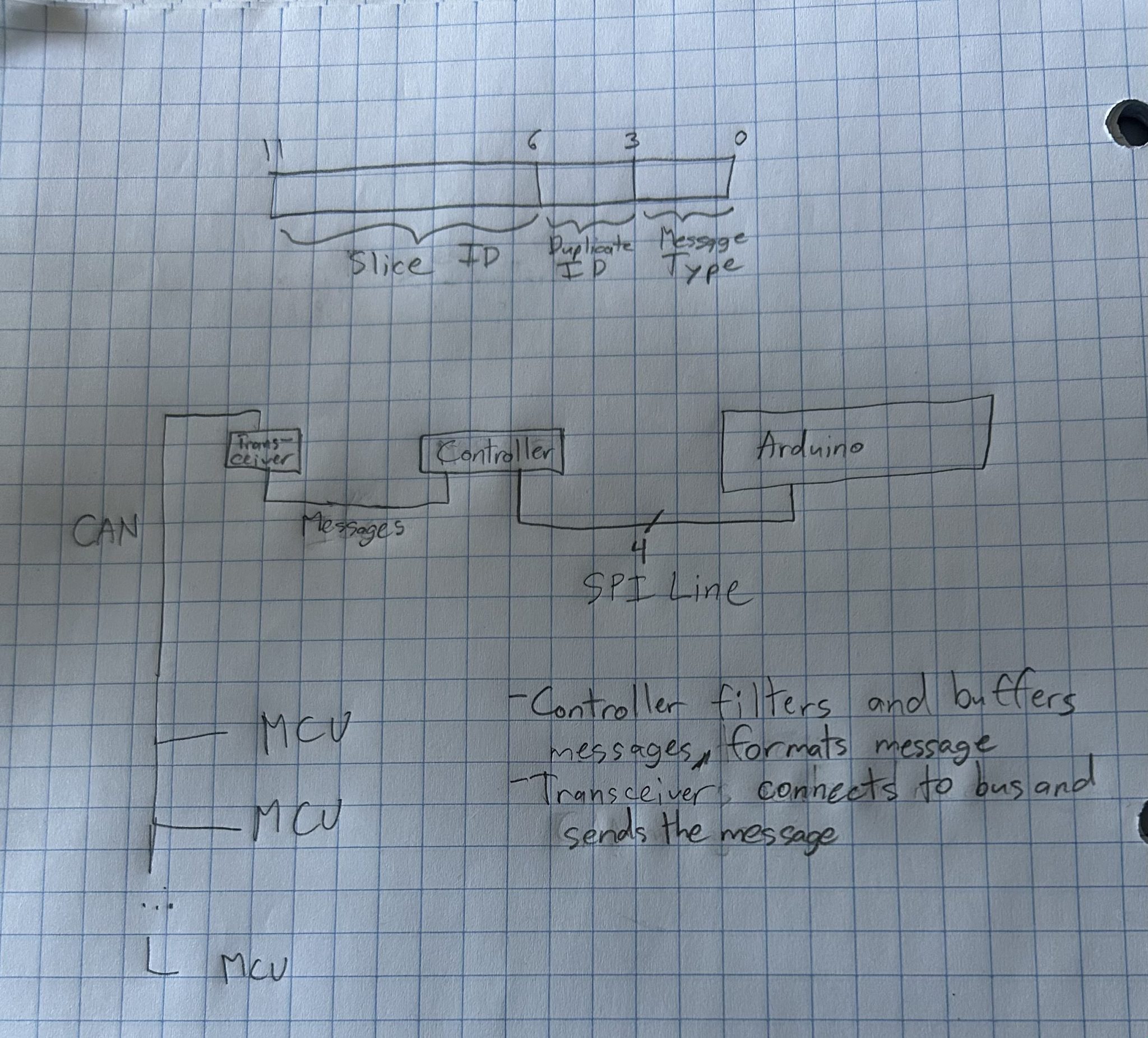
The main difficulty I believe we will experience is developing an identification system that is useful and easily expandable. CAN uses 11 bits as a default ID length which can be optionally expanded to 26. Currently I think that each slice type e.g. Vision, DAQ, BUNS, etc. will have a unique 5 bit identifier that is sent with each message. The next 3 bits will be used to identify duplicates, so if 2 DAQ slices exist, one will use 0x0 and the other will use 0x1. The final 3 bits will identify the message type that the slice is sending, e.g. sending data, requesting data. If a slice needs to be written to, one of these reserved commands can potentially be used by other slices on the bus. This is may change as more work and coding is done on the project, but this is the current protocol plan.
To-do
- Begin coding new protocol on old slices
- Flesh out what kinds of messages will be sent and how IDs will be stored on other slices
- We have ordered MCP2515 and MCP2561 as the controllers and transceivers to use. Arduino has libraries that support communication to these chips
- Begin PCB design of LOAF and old slices
- Need to modify existing PCB designs to support the CAN chips and bus
Potential Concerns
- We will not have our parts in quickly enough to prototype properly before Critical Design Review
- Will also prevent testing of any new code written
9/20/2024
Recap
- Confirmed identification protocol that will be used
- First 5 bits + extension bits will be used to identify the slice type
- Next 3 bits will be used to track duplicates in the system (two DAQs or two Visions)
- When initializing, slice will broadcast it’s ID with a reserved message type. If another slice hears it’s own ID being broadcast, will send back a write message to change the ID
- Final 3 bits will be message type – read, write, and initializing, then any slice specific messages
- Began integrating CAN into BREAD DAQ and Vision
- Began breadboarding with Arduino and MCP chips
- Had some issues with initial running of example code, need to do more testing
To-do
- Continue coding new protocol on old slices
- Flesh out what kinds of messages will be sent and how IDs will be stored on other slices
- We have ordered MCP2515 and MCP2561 as the controllers and transceivers to use. Arduino has libraries that support communication to these chips
- Begin coding CAN for ESP32
- Look into how much the ESP32 system can do by itself and what libraries are available
- Start adapting BREAD DAQ for Recyclebot
- Need to test accuracy of current temperature system
- If it is too inaccurate, may just adapt logging process for the current temperature tracker
Potential Concerns
- How will we encode controls into the system
- Slices need to know other ones exist on the system. How will the final slice know what exists?
- Only 8 bytes of data per message, what controls can we put into those bytes?
9/27/2024
Recap
- Finished integrating CAN into BREAD DAQ code
- Changed to mcp_can library by coryjfowler
- Gives more direct control over the MCP2515, allows us to set modes on the chip such as sleeping and enabling an output clock
- Added support for logging data from Vision on DAQ’s SD card
- Needs to be tested once Vision is updated
- Changed to mcp_can library by coryjfowler
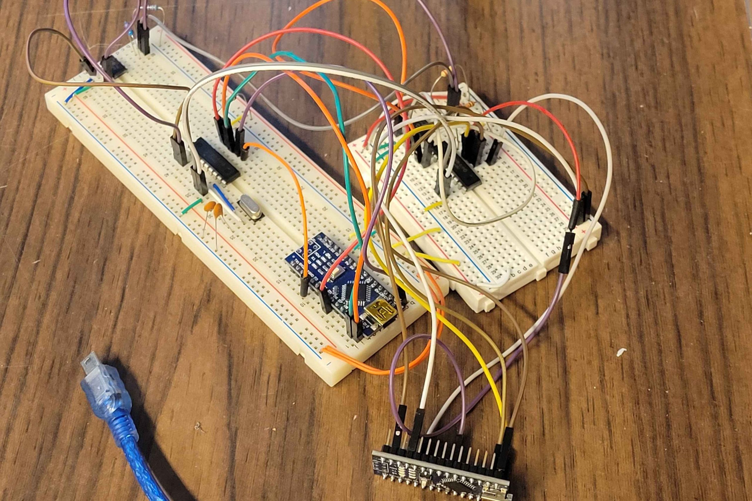
- Finished breadboarding with Arduino and MCP chips
- Were able to send messages back and forth between Arduinos
- Each MCP2515 controller needs access to a 16MHz clock or crystal oscillator
To-do
- Begin coding CAN for ESP32
- Look into how much the ESP32 system can do by itself and what libraries are available
- Start adapting BREAD DAQ for Recyclebot
- Need to test accuracy of current temperature system
- If it is too inaccurate, may just adapt logging process for the current temperature tracker
Potential Concerns
- How will we encode controls into the system
- Slices need to know other ones exist on the system. How will the final slice know what exists?
- Only 8 bytes of data per message, what controls can we put into those bytes?
1/26/2025
New Project: BREAD BiOS (Bioreactor Operating Software)
This semester OSHE is partnering with the Chemistry Department to work on a bioreactor they have set up. They are currently implementing a BREAD system to control pH levels, operate the heaters, and log data. This is all controlled and communicated to a website being run by the master ESP32 on the system. Our work on this project will be focused on making improvements to the currently implemented system by fixing the controls software, optimizing the website, and adding new slices.
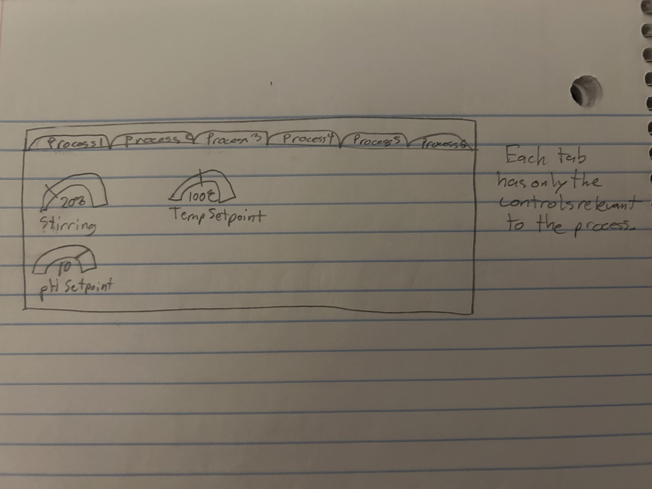
My main focus will be optimizing the website, testing the turbidity controls, and calibrating the thermocouples. We will be making improvements to the website as we are doing this by organizing the controls on the website, as seen in the picture below.
To-do
- Move the master control to a Raspberry Pi
- Will increase the processing power of the system, decreasing load time and hopefully removing all crashing
- Change what data is being sent for the website
- Currently sending all libraries with each send. Want to cache as much as possible to reduce load times
- Run tests on thermocouples
- Check that thermocouple is hooked up correctly based on MAX6675 datasheet
- Need to run tests to see if there is a consistent error in the thermocouples at high temperatures
- From there will decide if an algorithm can be made to correct the error or if a process for setting a correction needs to be created
Potential Concerns
- There will not be any simple way to fix the thermocouples. Not sure how in depth/how long it will take
2/5/2025
Recap
- Set up the Pi to run the website
- Using a Raspberry Pi 400 (Pi inside of a keyboard)
- Running new code from Cameron Brooks who is working on the same project at Western University
- Is not connected to the system yet
- Ran testing on thermocouples
- Heated thermocouples up to 85 deg C using a water bath
- Checked bioreactor readings against a known good thermocouple and the bath’s temperature readout
- Each thermocouple had a consistent offset from the correct temperature. For under 100 deg C should be able to measure this offset and put it into the system
- Offset was specific to the thermocouple, not the amplifier it was plugged into. This means the offset will need to be recorded on the thermocouple and input by the user
To-do
- Move the master control to a Raspberry Pi
- Hook Pi onto the system for testing. If it runs well, we will order a new Pi that can attach inside of the control box as a permanent solution
- Further Thermocouple testing
- The Pyrolysis process goes up to higher temperatures (about 200 deg C), and reportedly has a greater offset. Need to test if the offset changes at some temperature
- Update heater control to include offset
- Add a hard coded offset in the system for now, will eventually add a way to set it from the website
3/3/2025
Recap
- Connected Pi to the system
- Did not work initially because of differing voltage levels, so a level shifter was ordered for the I2C bus
- Added offset to thermocouple code
- Still need to do testing, waiting on update to Raspberry Pi to make sure it is working
To-do
- Move the master control to a Raspberry Pi
- Connect I2C level shifter so that the controls can be seen using the Pi
- Further Thermocouple testing
- The Pyrolysis process goes up to higher temperatures (about 200 deg C), and reportedly has a greater offset. Need to test if the offset changes at some temperature. A meeting is planned for 3/7/25 to test this
3/9/2025
Recap
- Connected Pi to the system
- Fully integrated Pi using the level shifter
- Still had issues with communicating over I2C, needed to change pin assignments in the sliceware code files to match our system.
- Discovered that Loafware does not actually send I2C messages when a setpoint is put into the website, just logs it on the database
- Further thermocouple testing
- Tested at higher temps up to 150 deg C, remained at a constant offset
- From reading a double pronged thermocouple, it seems that the failure is at the slice level, not thermocouple level
- Will try to fix this by just providing a constant offset on each slice that can be adjusted on the website
- Tested the turbidity sensors
- Have code from previous work that is being tested
- Did not work at all, provided the same readings with distilled water and 50% organic material water
- Not sure how to fix this, need to dig into code and find where the error is
- Set up a new Pi
- Using a Raspberry Pi 4 instead of a 400
- Will allow it to fit mounted inside the system, rather than as a keyboard outside of it
To-do
- Waiting on update to website from Canada group
- Will move to that update and then attempt to fix the I2C communication from there
- Investigate Turbidity sensor failures
Concerns
- Will not be able to find turbidity issue before the project is due
3/16/2025
Recap
- Set up Pi 4
- Ran into issues with MTU servers assigning a different subnet that had a firewall between our network and the Pi
- Got around this by switching the MAC address of the Pi 400 and the new Pi 4
- Attempt to Fix Turbidity Sensors
- Tried changing sensors to a different slice, appeared to need to be on the same slice as the motor controller
- Did not fix it, may be a sensor issue. Otherwise there is some code issue that I missed
To-do
- Fix I2C communication on the Pi
- Still no update from Canada group, will need to fix it ourselves by adding the I2C write command that is missing
- Investigate Turbidity sensor failures
Concerns
- Will not be able to find turbidity issue before the project is due