
October 19, 2024
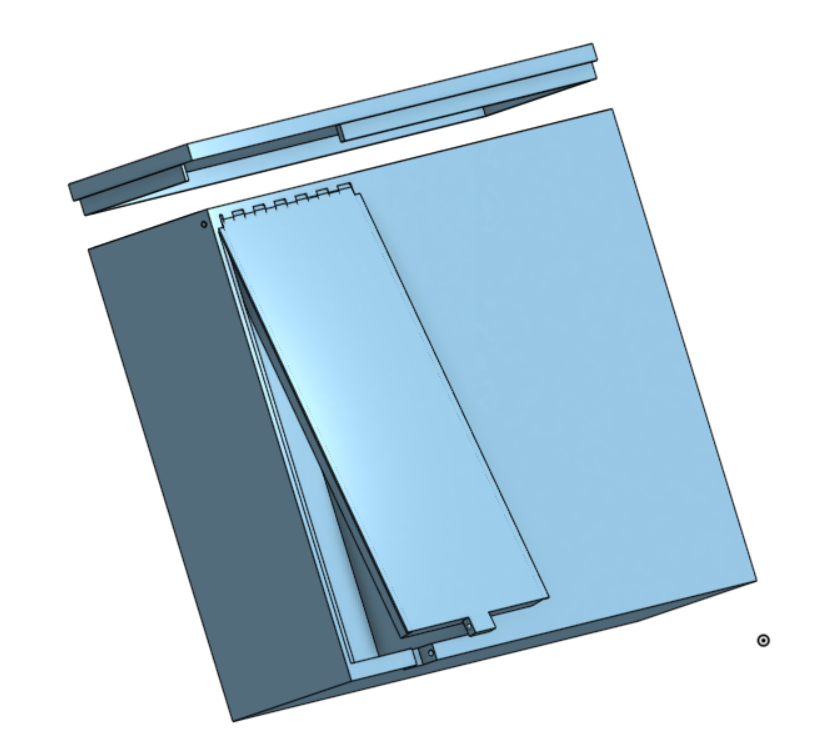
The case for the metronome has been made. Still yet to be made are the holes in the case to allow for the potentiometer to be adjusted and the LED to be seen. Software used was OnShape.
October 14, 2024
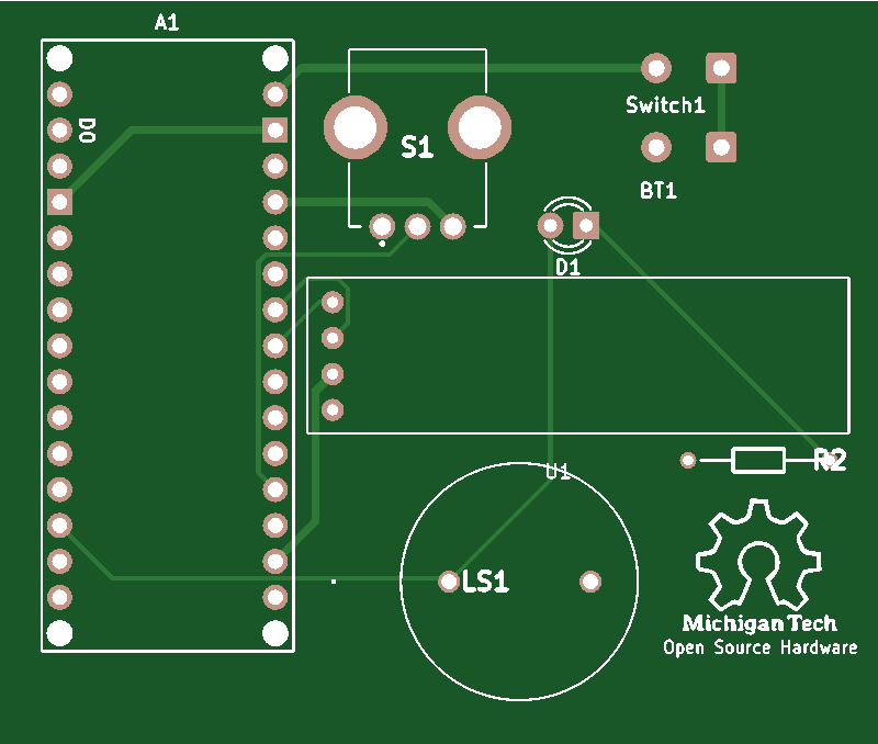
The PCB for the metronome was made in KiCAD and ordered from JLCBPB.com.
October 2, 2024
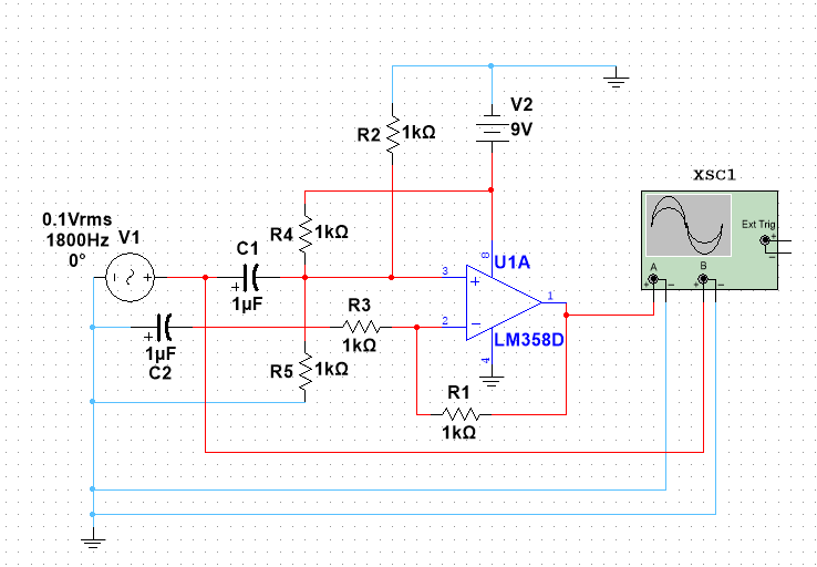
Below is the corrected tuner circuit. Values are not correct, but the layout is.
September 29, 2024
The components of the viola are all coming along nicely. This past week I spent a majority of my time researching and modeling the tuner’s circuit. Some useful resources have included online forums and circuit diagrams from Texas Instruments.
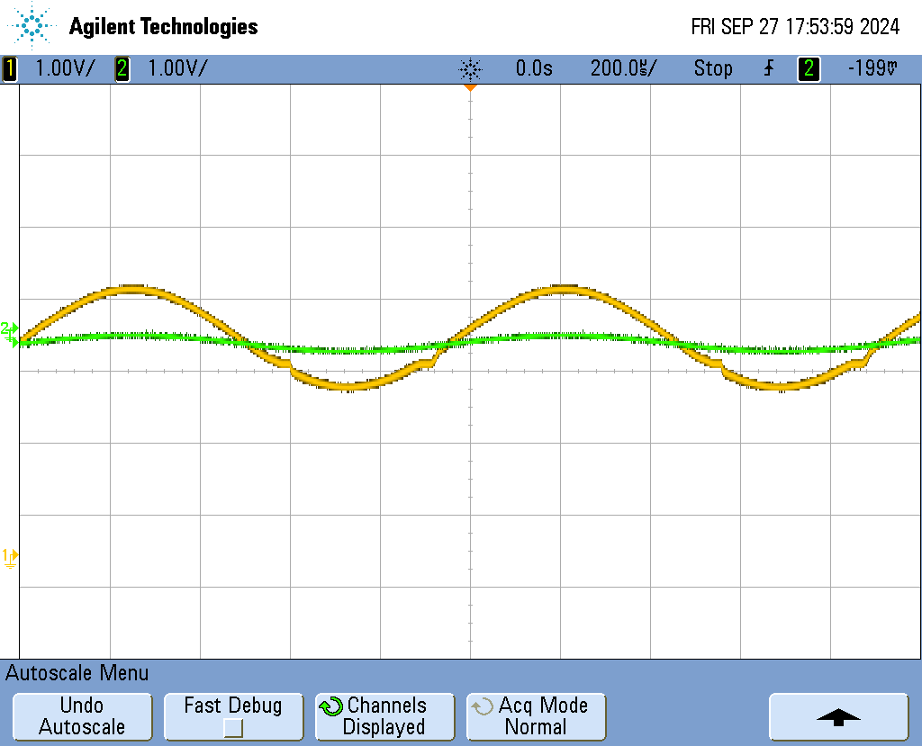
Multisim has been used to model various values and configurations. Right now the circuit amplifies, as seen in the oscilloscope image below, but there is an interesting clipping that happens when a larger voltage is applied. This is not, however, too large an issue as the electret microphone generally outputs signals 0.001-0.1 volts.
Next week will be preparation for CDR and finalizing the circuit. Also to be done is simulations on the peg box as well as a brute force physical test.
September 13, 2024
This is the start of Electric Viola’s last semester!
January 26, 2024
Here begins Electric Viola!!
To-Do List:
- begin modeling the body
- help team with the project shopping list
- further research for the body of the viola
- create an accurate diagram with dimensions to begin modeling the body off of
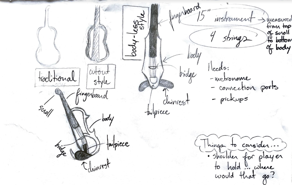
The bottom viola is the design I am envisioning
February 3, 2024
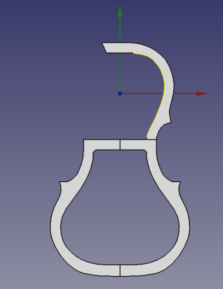
Modeling of the viola’s body has begun. I am working from a solid foundation of sketches inspired by commercial electric violas. This past week I felt bogged down by my lack of skill in 3D modeling, as a lot of time was spent researching how to make more advanced designs such as this. A concern I have going forward is how I am going to break the final part into the six parts it needs to be broken into in order to print it.
On next week’s to-do list is designing a connection system so that the parts will be able to rejoin after printing to form the final body.
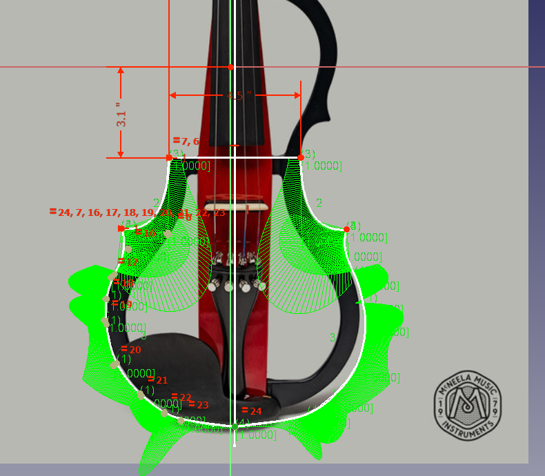
Working sketch of the body (FreeCAD), photo credit https://mcneelamusic.com/string/violins/premium-electric-violin/
February 10, 2024
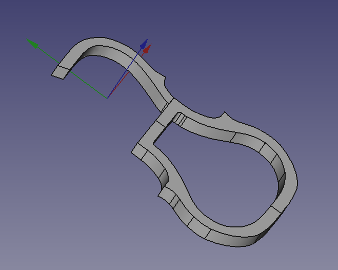
Above is the current version of the viola body. On my To-Do list for next week is to slice the body into five parts so it will fit on our printer. I will also need to design the joints that will allow the viola to be reassembled. We are thinking that for re-assembly we will use some combination of joints, glue, and PLA “welding”.
February 17, 2024
This week I worked on slicing the viola and creating the joining mechanisms. The joining mechanisms are giving me the most trouble as I am a beginner in FreeCAD so I do not know how to efficiently address problems as they arise.
Next week we as a team will be focusing on our Critical Design Review. For me as an individual I will continue working on the locking mechanisms and possibly print one or two pieces.
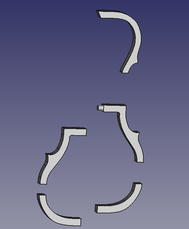
The sliced viola with one pin
March 9, 2024
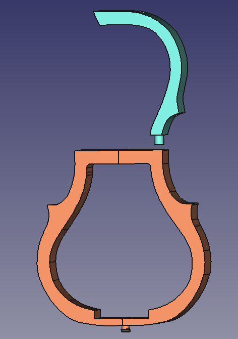
This week we reviewed the design and found a few problems that have been resolved (see image below). Namely, I sliced it prematurely.
Terminology update:
- We are now calling the center piece holding the strings, bridge, etc. the body. The surrounding piece will be called the frame.
This next week I will be designing the body. It needs to be compatible with the wooden fingerboard we purchased, it needs to fit in the frame, join with the head, and it needs to hold the bridge.
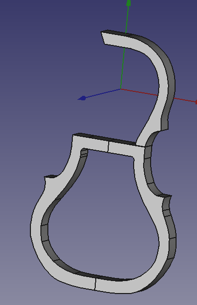
Updated frame
Body design and frame considerations
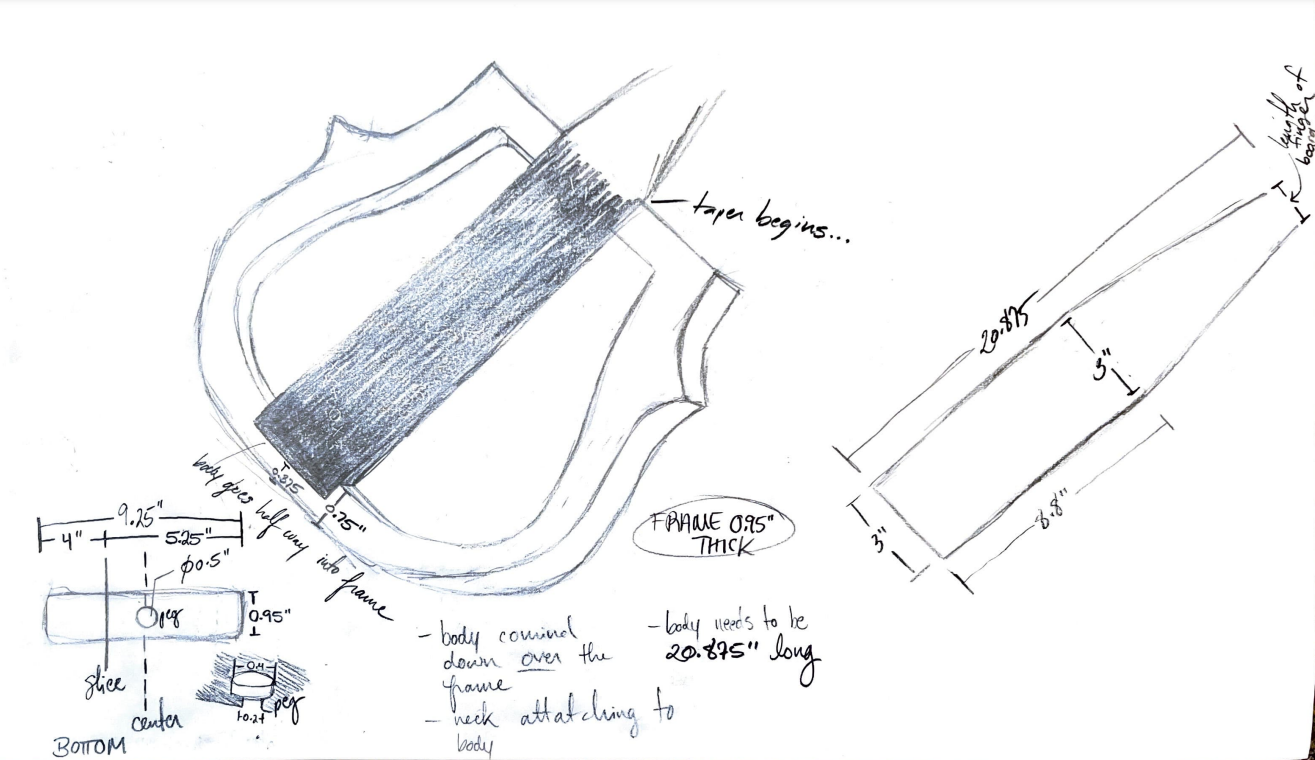
March 17, 2024
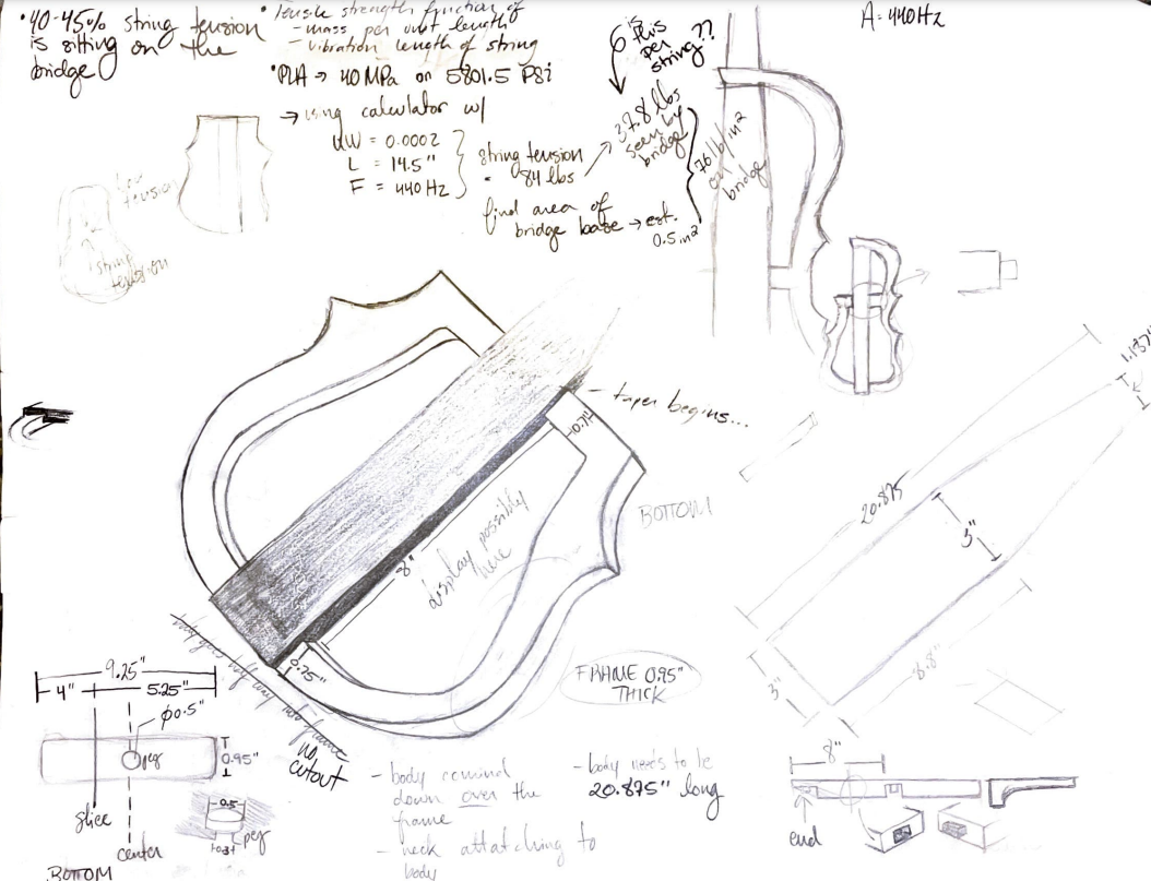
This past week I have been doing research into the body of the viola. This includes literature on tensile strength and 3D printer material strength, as well as equations for the tension of the strings. This research has lead to slight modifications in the frame of the viola, as can be seen below.
Construction of the body begun. The part enclosed by the frame will be in one solid piece. While this is near the max that our printer can handle, it is crucial for this piece to be strong as the bridge will rest on this part, and the bridge will see 40-45% of the string tension. An interlocking peg system will be added to this design.
I have also been in contact with a violaist from the music department who can possibly connect us to Mark Woods. I will be reaching out to her for design critiques.
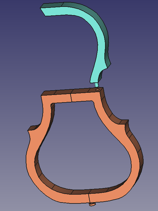
Latest version of the frame – note there are finally holes for the peg
Start of the body
March 25, 2024
This past week was more of looking into FreeCAD features such as assembling all of my bodies into one file.
There are pegs in place to prevent up or down shifting. The bridge and the strings will provide a downward force of approximately 114 psi.
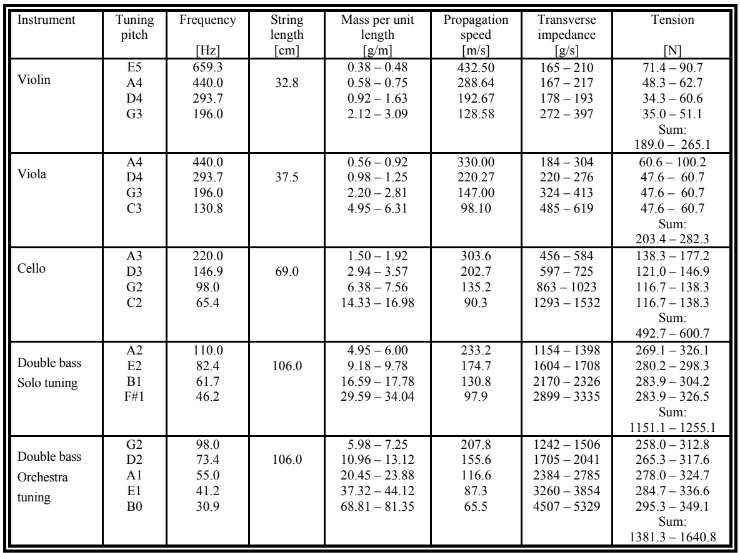
Source: https://knutsacoustics.com/files/Typical-string-properties.pdf
Above: https://www.thomastik-infeld.com/en/stringtelligence/dictionary/what-is-string-tension
Electronics arrive this week.
There has not been an update from our contacts in the music department.
This coming week I will be finishing the rest of the body. Also, I will be making some small prints test my joints.
March 31, 2024
Electronics arrived this week, although a few setbacks unrelated to the viola have prevented us from either working on them or printing more parts.
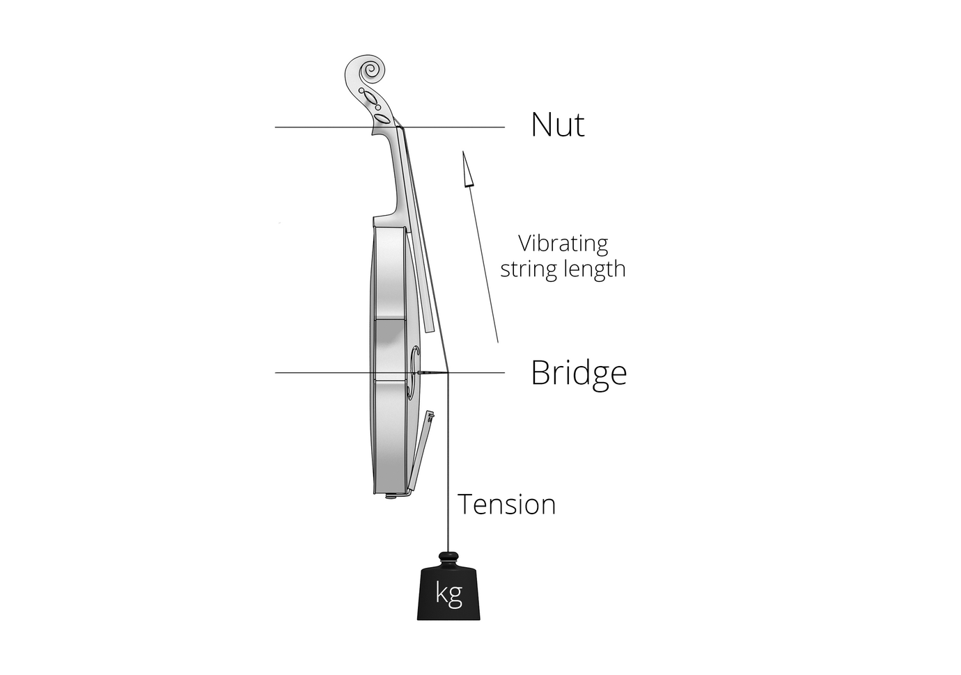
I am currently working on setting the neck, a process which is very particular as the strings need to come across the bridge at a 157 degree angle.
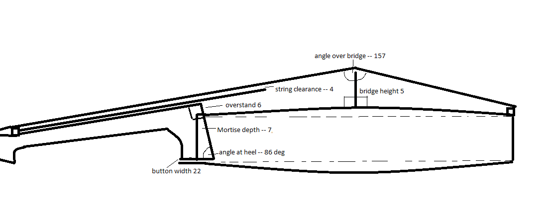
Image credit: https://thediyviolin.blogspot.com/2016/10/setting-neck.html
Test joints were made, although not printed.
April 6, 2024
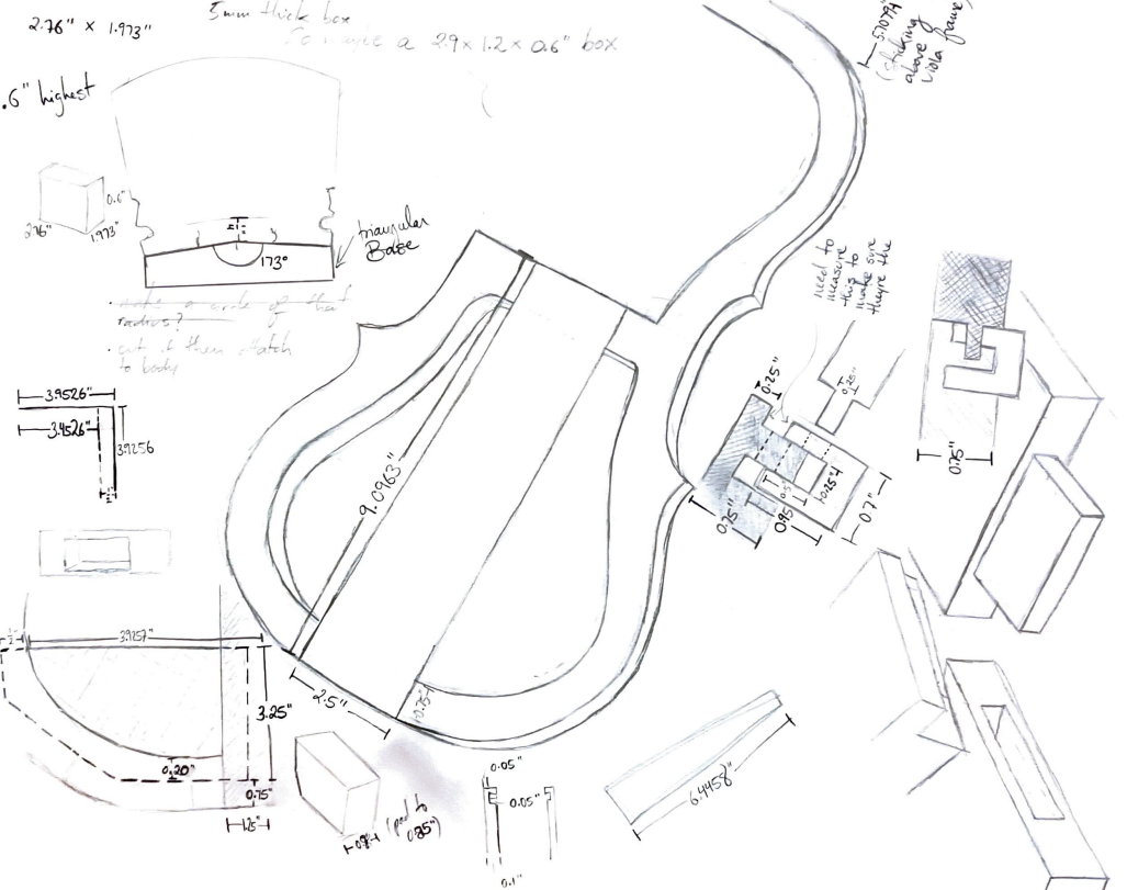
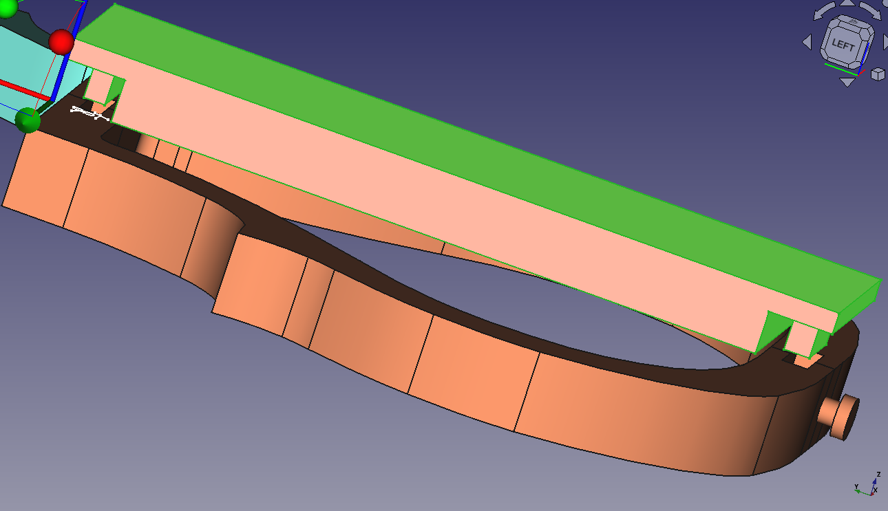
A lot of sketch has been done as I hone in on final design choices. There is now an electronics case, although it still needs a lid and a permanent method of attachment. There is now also a mount for the bridge (the body is flat, but the bridge needs to sit on a 7 degree angle for each foot).
April 13, 2024
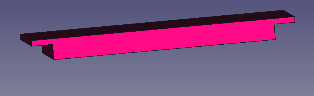
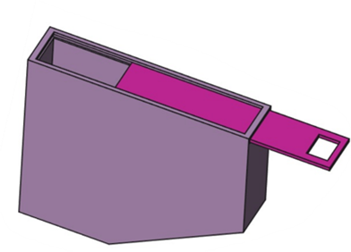
Since the last post, we now have access to a printer that can print the body (pink piece) as a singular part. Design adjustments have been made accordingly.
Both of the electronics cases are built and equipped with lids. There has been significant adaption of the body to account for the two nine volt batteries that will need to be supported by the viola.
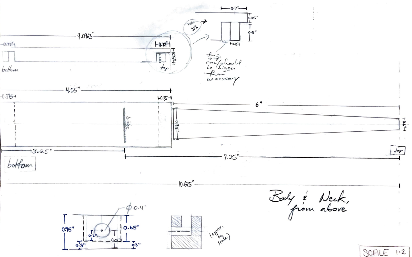
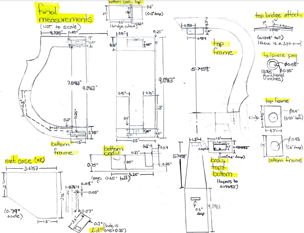
Additionally, I triple checked all of the measurements and drew out all of the parts.
April 18, 2024
This past week I presented the viola to the rest of OSHE. Here are some slides from my presentation that nicely highlight the viola timeline and current standing.
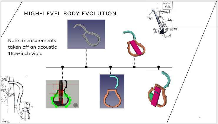
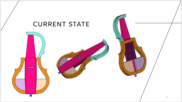
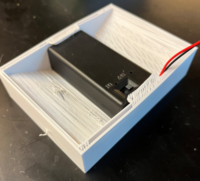
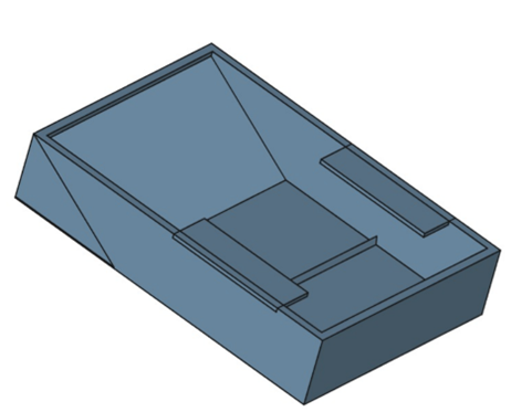
One big addition since last week is the battery case. It can be seen here in its prototype stage and as a final model.
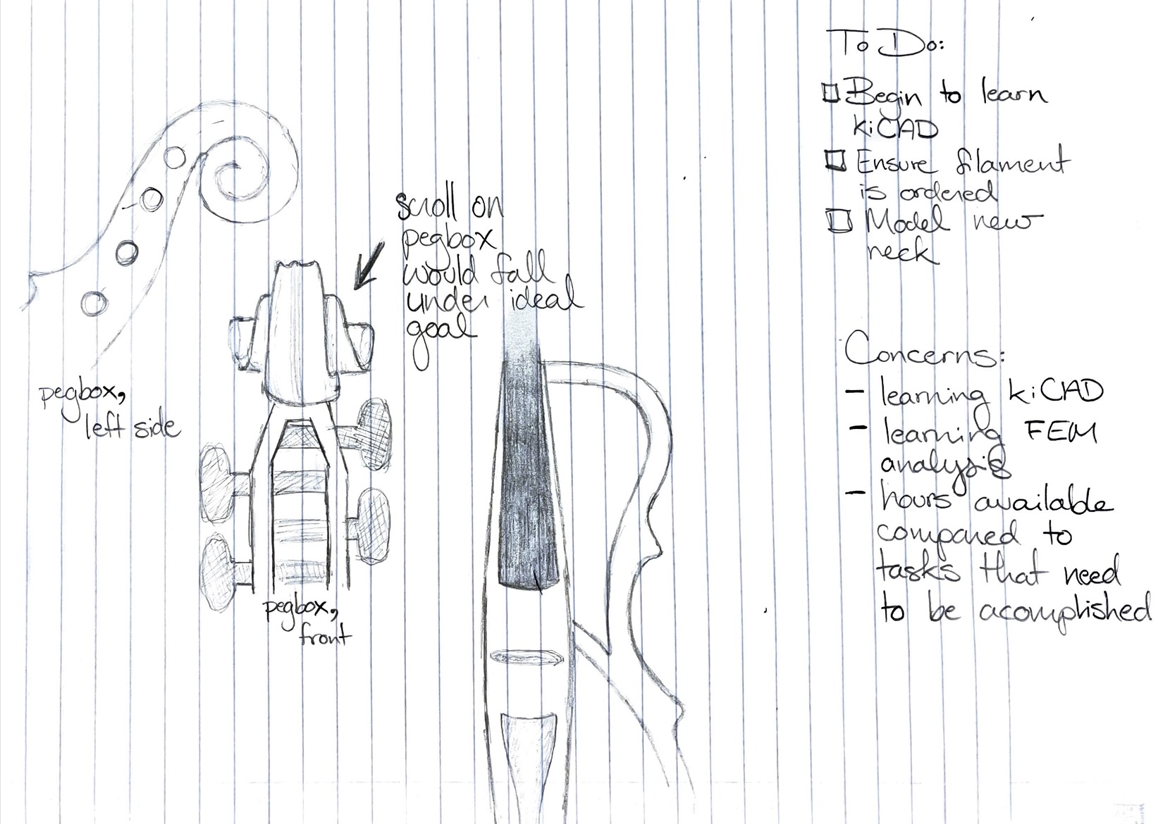
Parts are being printed right now, and the last thing to design is the neck and pegbox.
September 22, 2023
Localized Lyme Disease will be a two-student project tasked with reducing the spread of Lyme Disease in the Upper Peninsula of Michigan.
To begin the project, we met with faculty from the Forestry Department of Michigan Tech to get more details on what is expected of the project. We ran our original project ideas by them, and by the end of the meeting the only change we ended up needing to make was a change on the time parameters, with the new goal deployment time shrinking from one month to one week. We were loaned two Sherman traps (pictured below) to give a starting point for the design of our treatment centers (TCs).
As we are only a team of two students, our budget is very limited and will be a strict parameter of the project.
Sherman trap
As of right now, the box’s entry ways will be check valves at the suggestion of our Enterprise advisor, Dr. Oberloier. This is to ensure that each mouse passes through the entire length of the tube/trap instead of simply turning around and leaving the way it came.
We worked on some basic prototyping, pictured above, of the basic trap design. Additionally, we prototyped possible designs using wood and stencils which we found of the internet. Our next step will be to take the wood/paper models and build them in FreeCAD, an open source CAD software. Additionally, we will again be in contact with the Forestry Department faculty for anther round of clarifications and questions.
The PDF of the stencils can be found here: https://woodgears.ca/farm/mousetrap_plans.html
October 1, 2023
The TC is going to utilize tick medication-soaked sponges as the administration method. Each wall of the TC will tentatively have slots to insert the sponge, and the roof will be hinged to allow insertion from the top. The physical box is currently being made in FreeCAD according to the sketched prototype show below.
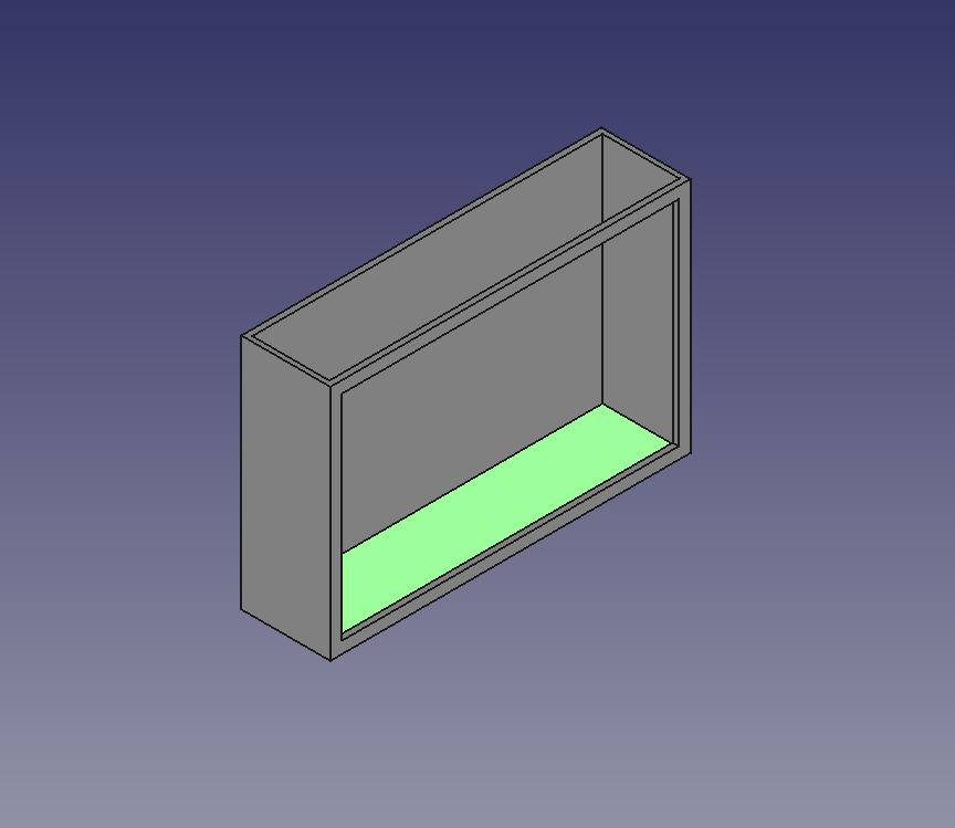
Side wall drawn that I drew in FreeCAD
I am tasked with researching the sensor that will be used to track the number of mice entering the trap per deployment. After some preliminary research, the strongest candidate is a weigh sensor using a MKR Zero Arduino and a load cell with an amplifier. The sensor will be on the floor of the TC and will also have a battery attached to it. Next week we will incorporate the sensor into the physical design of the trap.
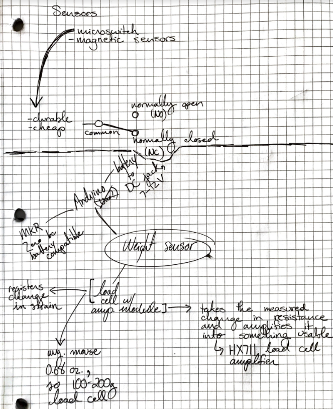
Sensor notes
Next week, we hope to have a printable CAD file, as well as begin to prep for the upcoming Critical Design Review, which is a short presentation to Dr. Oberloier and our peers on our project.
October 7, 2023
The name of the trap has been updated to Tick Repellant Administration System, or TRAS for short. The CAD file has been completed and printing has begun. No progress has been made on the implementation of the sensor, but the first design will be solidified by Monday evening, 10/9.
Next week we will be preparing for out Critical Design Review, or CDR. Slides for that have already begun.
We have compiled a comprehensive parts list that we will need to order.
Additionally, we will be gathering the highlights of the TRAS and putting together our social media post.
Update: here is our first social media post.
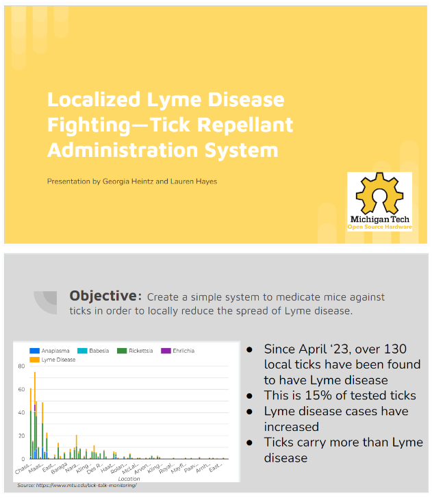
CDR slides
Above is one of the two doors
October 28, 2023
We have decided that the load cell will be on the floor in the center of the trap. The battery and any other components we might add will be housed in a separate, exterior electronics case.
Since the last update, we have gathered a better picture of the tasks we need to accomplish moving forward. Among those is the code needed to run the Nano; I finished writing that today.
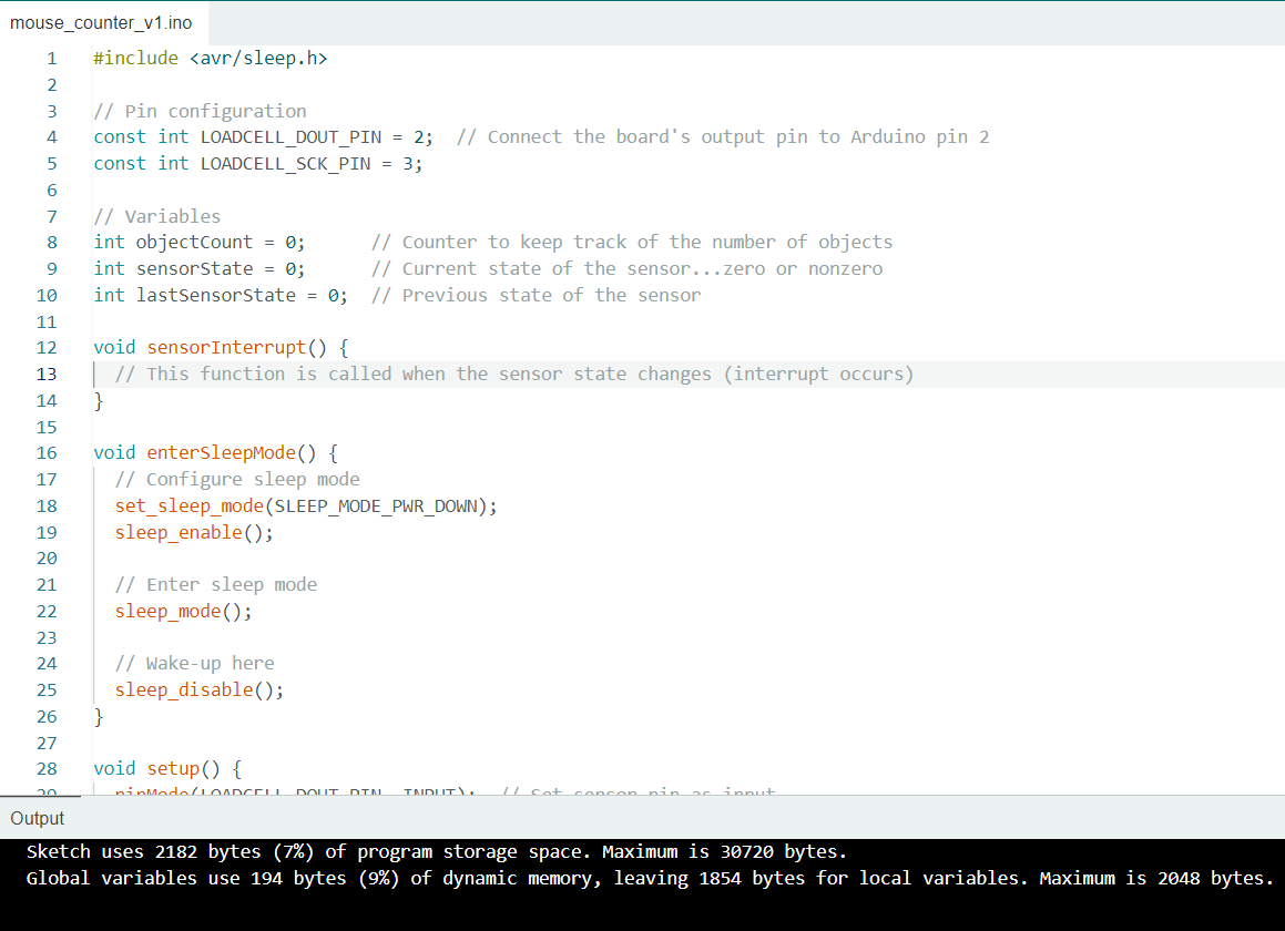
Code for the Nano…the device will be in sleep mode unless a mouse triggers the sensor
We are still waiting on some parts for the load cell, preventing immediate testing. When it arrives, I will be able to take the necessary measurements to finish the load cell mount.
We have since updated our sensor system to also include a real time clock module (RTC). My teammate is working on implementation. Once the load cell and HX711 amp come in, we will be able to finish building the circuit.
Next week we hope to have all of our parts in. We also plan on finishing all of our tasks in FreeCAD so that we can begin assembling. Still to be decided is what type of bait we will be using.
November 9, 2023
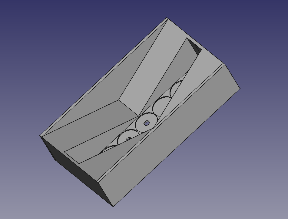
At the recommendation of one of our peers after our Critical Design Review presentation, we have updated our design to include an elevated reservoir of tick repellant that will aid the sponges. The reservoir will be attached to the inside of of the TRAS, and yet to be made is the rectangular, removable wick holder that will rest in the rectangular cutout of the model below. The wick holder will have seven wicks attached to it that allow for the repellent to travel from the reservoir down the wicks and onto the backs of the mice who enter the trap.
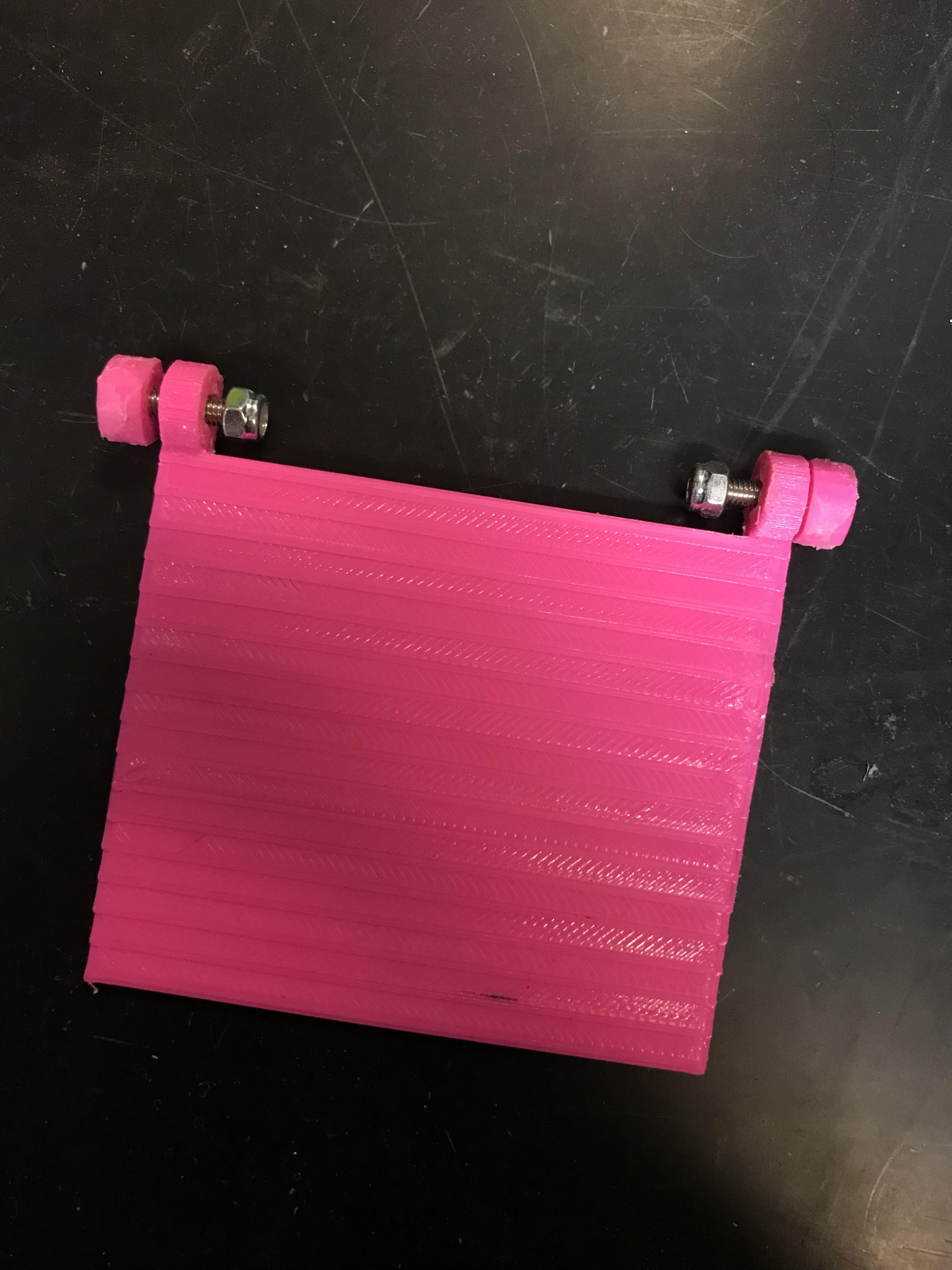
Since the load cell has arrived, the necessary measurements were taken and the mount was built (pictured below).
This week we encountered some errors in our load cell, which has led us to believe that it is damaged. A new load cell will be ordered.
We also have errors in our code, but we cannot fix it until we have a functional load cell.
Next week will hopefully have a new cell so that we might finalize our code.
Reservoir
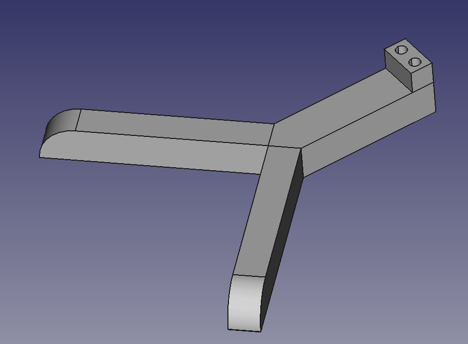
Load cell mount
November 16, 2023
We have consistently been encountering problems with the 3-D printers in our lab, hindering our progress greatly. We now have all of our parts in, including the new load cell and all of the material to make the wick holder. We will be attaching circular metal wick holders to each one of the circles shown below, and then the wicks will be threaded through them and secured with glue.
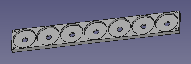
Wick holder
The reservoir has been updated to the design below. The wick holder will now rest below the reservoir in a two grooves which will be cut into either of the TRAS’s side walls just below where the reservoir will be attached. A lid will be made to rest in the groove surrounding the reservoir.
Updated reservoir
The code is successful at counting the number of objects placed on it, as well as reading a weight.
We have decided that for demonstration purposes we will forego bait. If the device were to be deployed, we would use balls of peanut butter tightly wrapped in parchment paper. We will also be foregoing real tick repellent as our budget does not allow such an expensive purchase, and for demonstration water will work equally well.
November 30, 2023
Again, issues with the lab’s printers are slowing down completion.
We have also decided to add a micro SD card module, which I will implement.
We have assembled our code and our wick holder, and smaller parts such as doors and doorframes are printed and waiting for the main body.
Our second social media post can be found through this link.
December 7, 2023
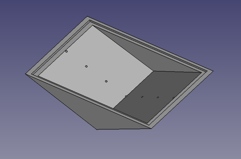
We now have everything save base and the main lid printed, the code is complete, the wick holder is assembled. Below is the circuit assembled and in its case. The case also has a case, not pictured.
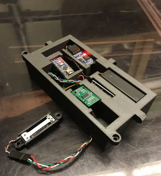
Load cell, HX711 amplifier, Arduino Nano, RTC module, micro SD module, and battery all in their case
December 15, 2023
I failed to take a final picture, but our TRAS was successfully assembled and presented to Dr. Oberloier. We received 100%.
Our finished product had two check valve doors, one removable door frame on the entrance door (this was modular so that a smaller frame could be attached if you wanted to even further limit the size of mice entering), a removeable lid for both the electronics case and the trap, and a complete sensor system. The electronics case was attached to the side of the trap.
Further versions of the TRAS would include exterior supports to allow for a more secure deployment as well as a smaller electronics case.