
4/20/2025 – Final Project Update
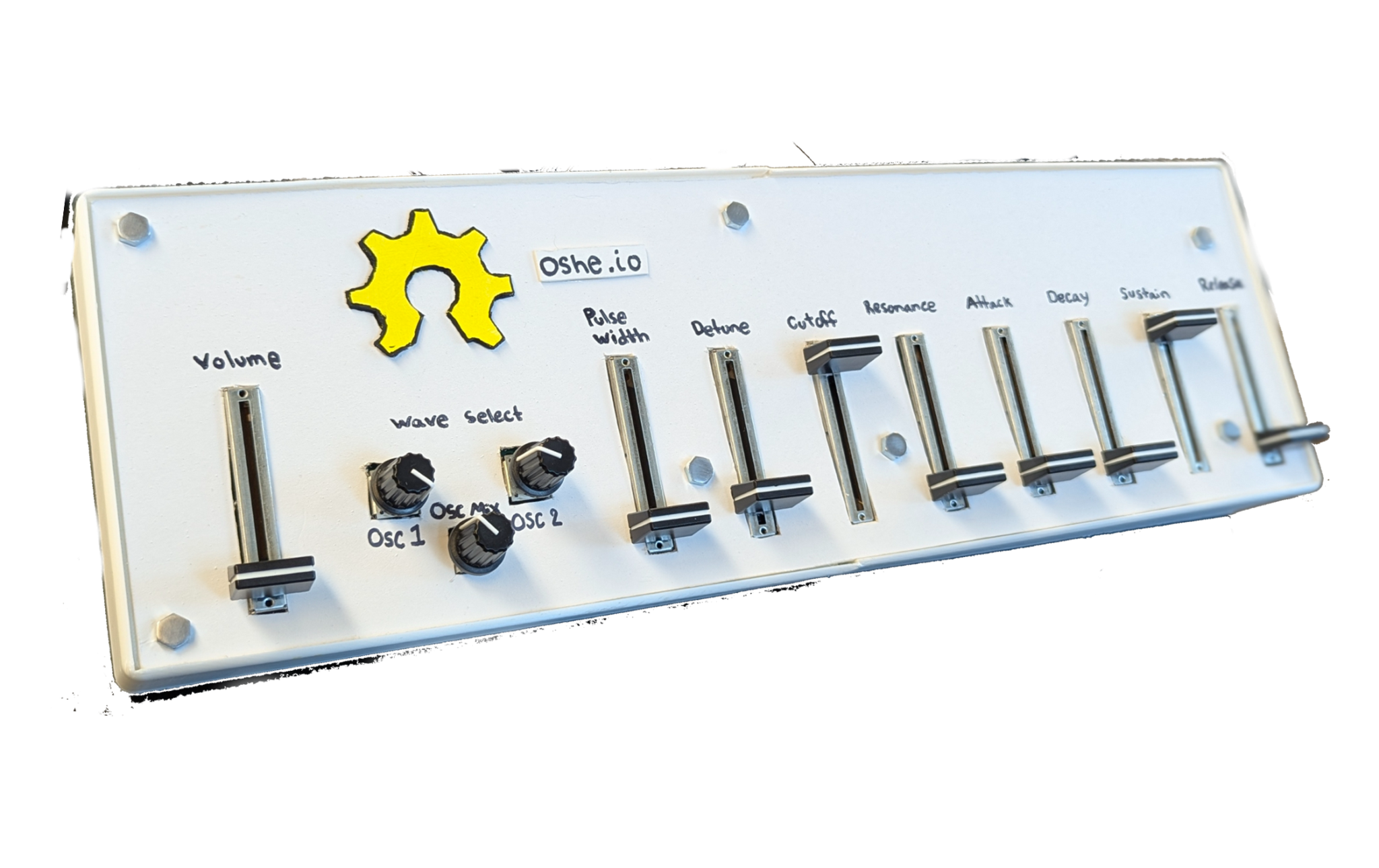
- Below is a photo of the synth in its final configuration for the semester. It’s finished, all set for use, and was reviewed at Design Expo. I’m incredibly proud of the work done.
- Next thing to do is simply finalize and publish the report for the Synth design, including code, CAD files, and other stuff by Friday.
- TODO: 4/20/2025
- Finalize report, submit and publish design documents
- TODO: 4/20/2025
4/13/2025 Update
- This past week, we finalized the design and worked together with the Recyclebot and OSTR teams to prepare for Design Expo this week. Thankfully, this took not too long.
- In addition to this, line level testing was done for the report. The measurements taken show that the audio of the device is capable of line level audio outputs.
- Finally, the report draft was written and submitted on April 12th for review. We’ll be finalizing that this week.
- TODO: 4/13/2025
- Peer review for Final Report Drafts
- Finalize report
- TODO: 4/13/2025
4/5/2025 Update
- After this past week, the design checkoff was completed. A finalized version of the prototype was created and tested. I’m happy with what we’ve done! Below is a photo of the completed prototype.
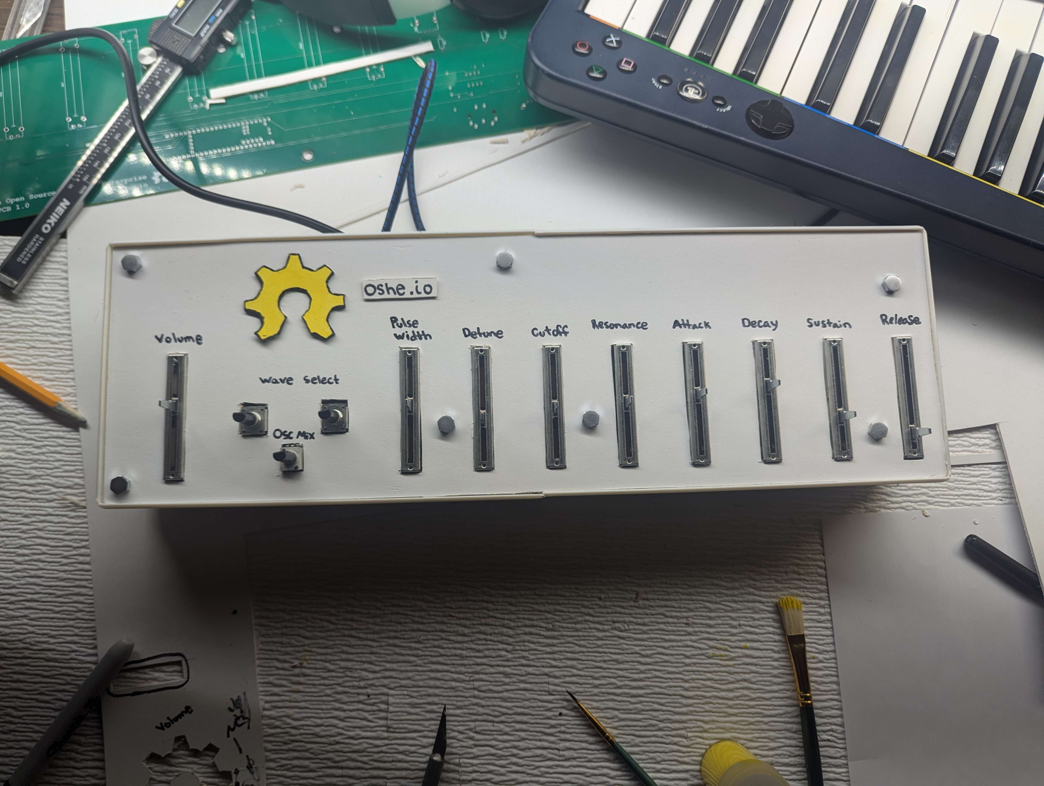
- Overall, it could have been made slightly narrower, but it works well enough for our purposes.
- The only major issue was that we have had no testing on the line level capabilities of the device. In the coming week, I’ll need to work with the team in order to verify the line-level output capability.
- Additionally, my team will be preparing for Design Expo this year, along with several other teams here at OSHE.
- TODO: 4/6/2025
- Line-level testing
- Write report
- Prepare for Design Expo
- TODO: 4/6/2025
3/30/2025 Update
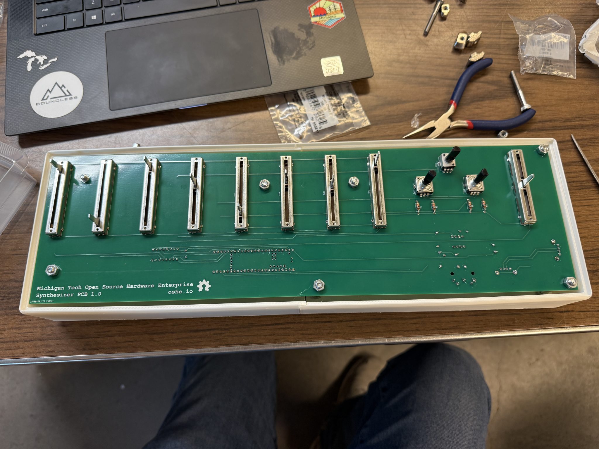
- After working with several of my team members, as well as some assistance from another team with a very nice printer, the case has been printed! Shown above is a test assembly of the board.
- So far, it still needs to have a cutout made to route cables, but it also needs to have the two halves plastic welded/taped together in order to complete it.
- With a little bit of time it should be ready for testing this Thursday. I’m a bit worried about damaging the PCB in the process, but that will simply require a careful eye and steady hand.
- TODO: 3/30/2025
- Finish assembling the board, wire it up and go from there.
- Complete testing of the board in its enclosure.
- TODO: 3/30/2025
3/23/2025 Update
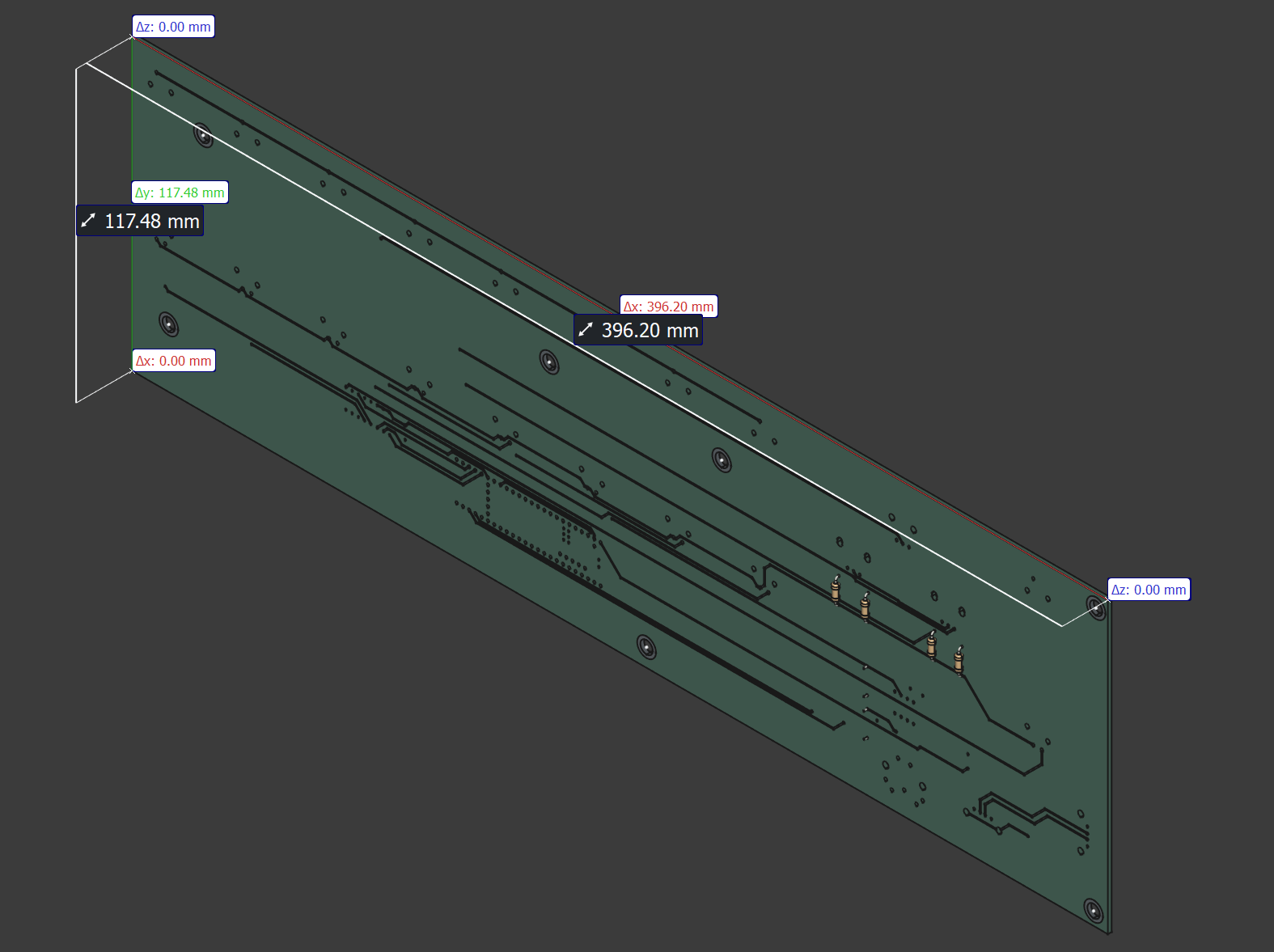
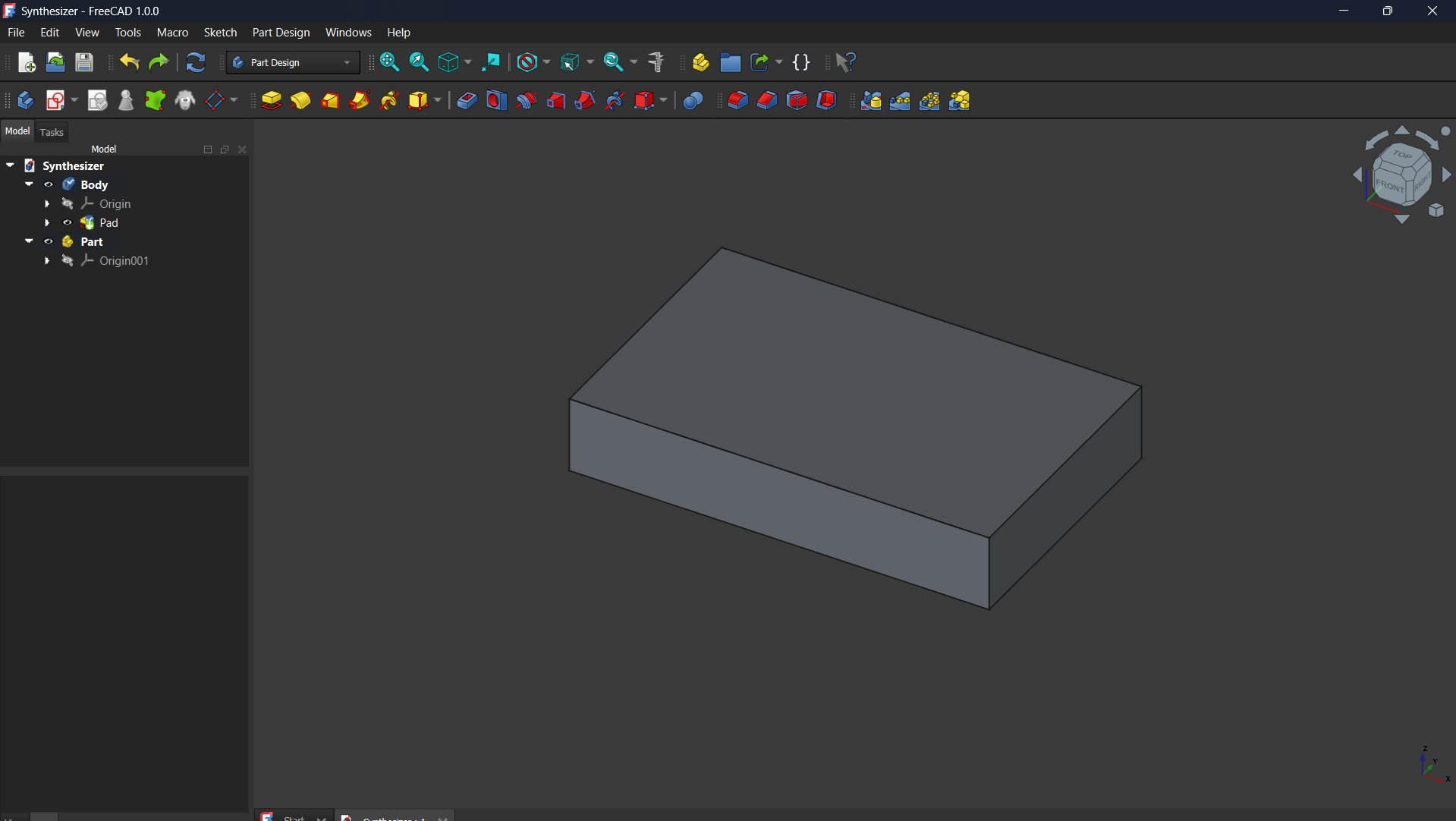
- The PCB design is finalized, and I’ve got the PCB into FreeCAD. At the moment, my current task is to sketch out the outline of the board, as well as the hole locations and diameters.
- Standoffs will be used to mount the case to the board, with clearance on both sides for the board itself, as well as the sliders.
- FreeCAD is not proving easy to use…then again, no CAD is easy, as I have no experience with it at all. Nobody on the team has any experience with it really, and that’s one of the main concerns I have for this week.
- This lack of experience has limited my ability to create the design effectively. I’m spinning my wheels.
- TODO: 3/23/2025
- Finish Enclosure design and make it
- Assemble the board with soldered components, ensure functionality
- Pray that it works
- TODO: 3/23/2025
3/16/2025 Update
- An initial design for the PCB is effectively done! The good news with this design is all the traces look good. The biggest issue at the moment is width; the board is quite wide and will require the case to be printed in separate chunks.
- After looking at the design of the board itself, it may be productive to revise some physical components in order to narrow the board
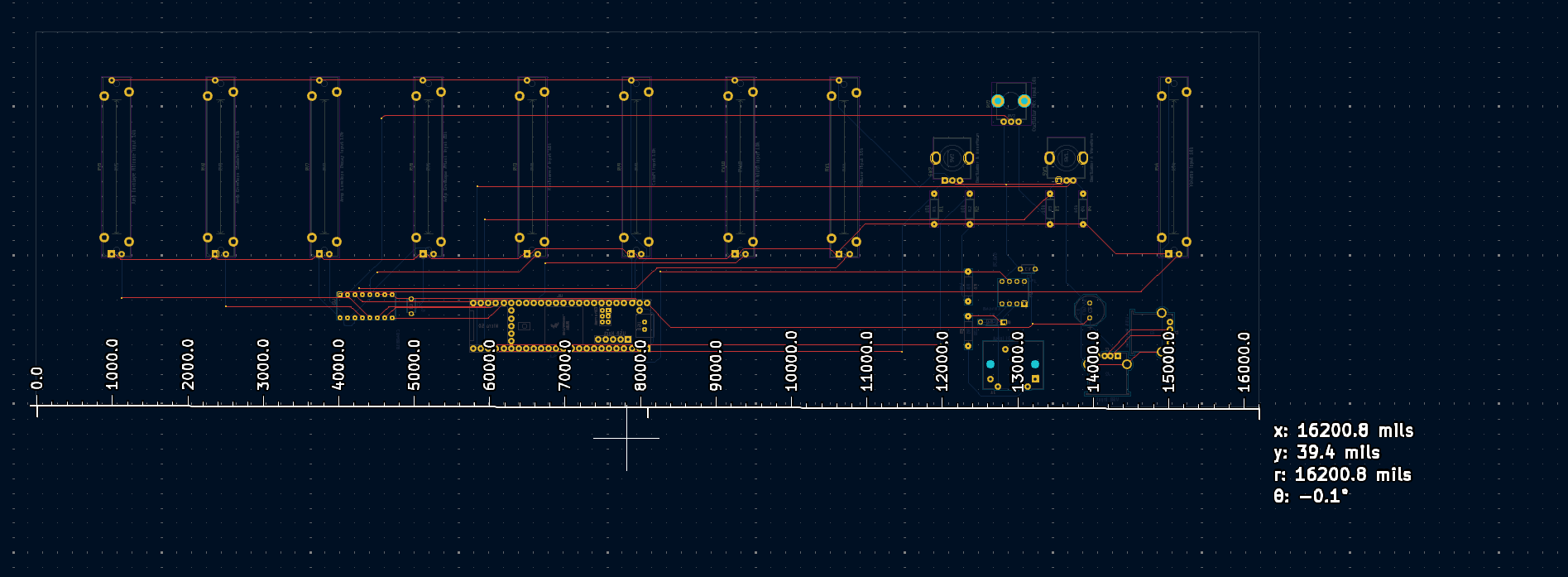
- Currently the fader caps are quite wide, which necessitates wide tolerances between the faders so they don’t physically interfere. Thankfully, the potentiometers used in this design use a generic 4mm stem, which gives flexibility in what parts can be utilized.
- Todo 3/16/2025:
- Order smaller fader caps for spacing reasons
- Put together two-piece case design in the event it can’t be made more narrow
- Assist teammates with revising PCB design
3/9/2025 Update
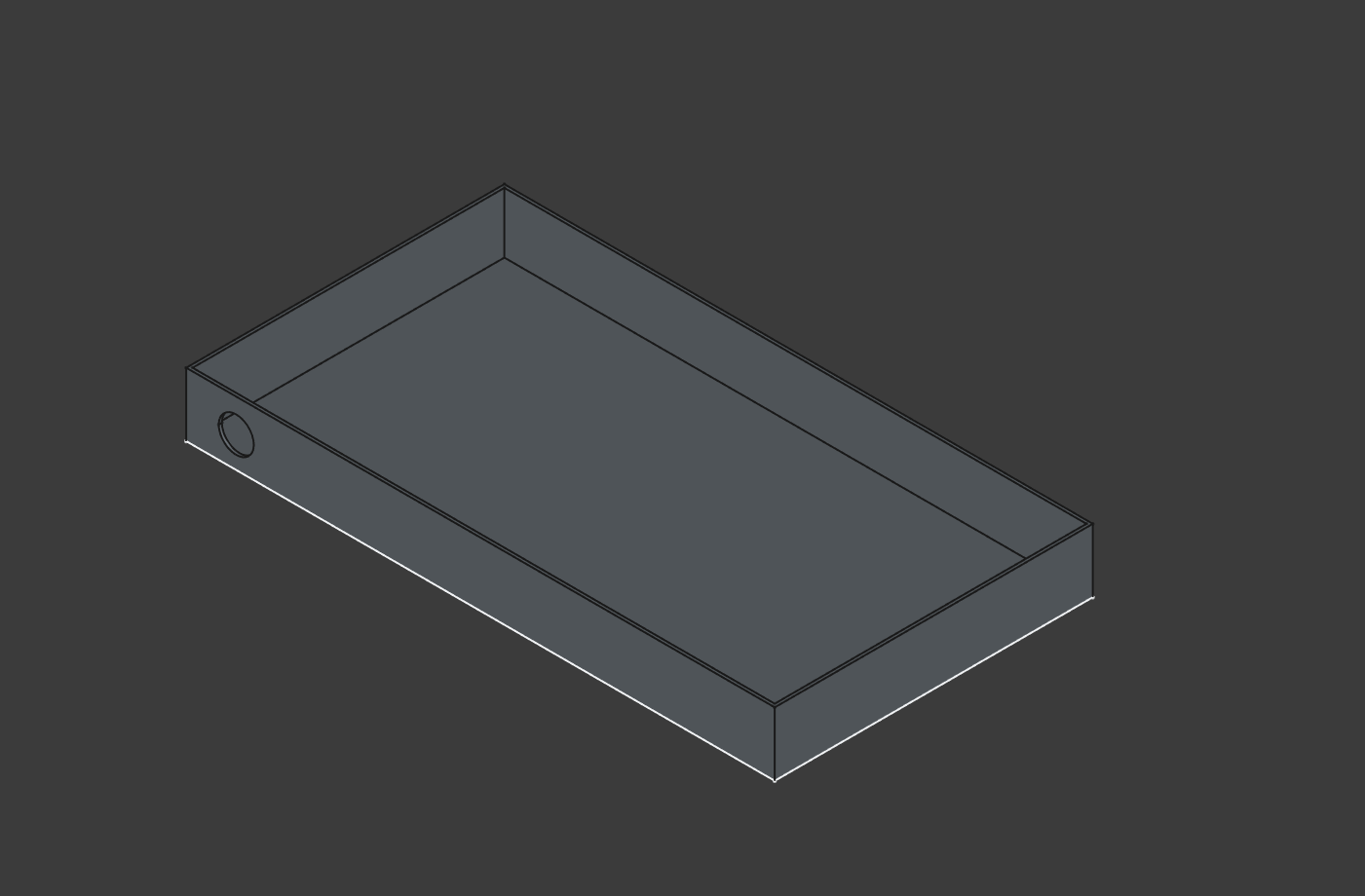
- After meeting with the team, I have a more refined CAD model created for a basic enclosure. A lot of the finer tolerances are going to be measured out/determined later when the PCB file is finalized.
- A branch has been made that contains the CAD file, and another branch we have contains the PCB design.
- I attempted to print a basic prototype of what I had made, but the print failed halfway through. Currently still need to go and try that again.
- Todo 3/9/2025:
- Redo test print, hopefully this time it works instead of failing halfway through
- Refine the current design to include more ports for USB power as well as 3.5mm audio out
3/3/2025 Update
- Created an initial CAD project for the project
- TODO 3/3/2025
- PCB design file still needs to be synced up
- Code base still needs to be synced up
2/16/2025 Update
- Last week, we had CDR. As it turns out, analog is ridiculously hard to work on at scale compared to all digital. As a result of this, and bad data from testing, we decided to ditch it.
- We’ve redone the entire setup for DSP instead of an analog/digital hybrid.
- Now, with the existence of a Git repo for the codebase, we’re going to set it up for the code and the PCB design. This needs to be done in order to sync up collaboration between team members.
- Todo: week of 2/16/2025
- Sync up PCB design file with new setup
- Review current code base given the new DSP hat exists
2/4/2025 Update
- Parts have arrived from our latest order. We still need to go in and properly test the upgrades/changes made to the filter.
- New parts have arrived, so we’ll have to test those on the envelope chip in order to get this set up.
- Todo: 2/4/2025
- Create initial PCB design file with KiCAD
- Set up designs for testing the AS3320 filter chips
1/26/2025 Update
- In the middle of last week’s meeting, we found a bag from Portugal full of AS3320 filter chips…we ordered it back in November and it came over break. We’ll have to test that very quickly. No real updates other than that.
- Only concern at the moment is not having enough breadboards to work on the project with. Hopefully (hopefully) we have enough on hand. Otherwise, we can order more but it’ll be very annoying to work through.
- More parts were ordered on Friday 1/24, including parts necessary for testing an alternative envelope generator IC.
- TODO: 1/26/2025
- Same as 1/23/2025, no major updates since 3 days ago
1/23/2025 Update
- After meeting with the team last week on 1/16/2025, we’ve set goals for the coming semester.
- Teensy 4.1 being used is awesome, and there’s lots of progress that’s been made on the synth itself. However, more work needs to be done on the envelope generation.
- The envelope generator/ADSR control needs to be troubleshot or modified to get it to work with a hardware envelope generator and VCA.
- In the event this can’t be fixed, the Envelope IC and VCA might be scrapped in favor of a Digitally controlled envelope, but this remains to be seen.
- TODO: 1/23/2025
- Research filter designs with user controllability, generate parameters for control.
- Find (stable) output amplifier designs usable for the project
- Create initial file for PCB design on KiCAD
- Just to start the process, this will not be used entirely for the final design.
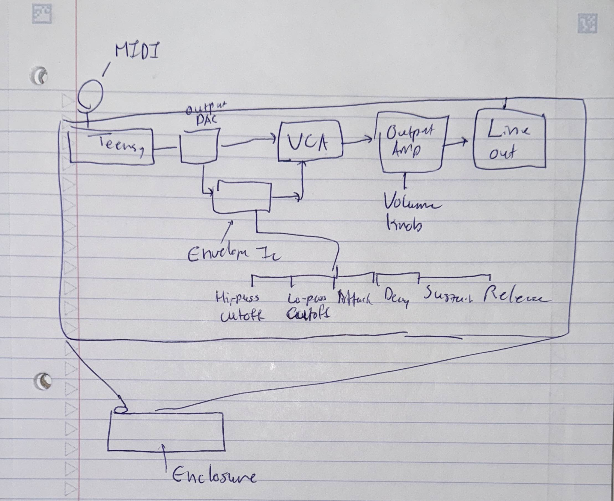
Below is a rough idea of what the full system might look like at the end of the semester.
10/13/2024 Update
- After meeting with the team on 10/8/2024, we discovered the code was in fact the problem
- The Arduino Mega used for testing this circuit was not playing nice with the MIDI library used in the original code.
- The issue arose from how the original code attempted to decode MIDI note data incoming via serial. A different working library was implemented instead, and the note data was subsequently decoded correctly.
- TODO: 10/13/2024
- Look at code structure for MIDI input processing and note generation, investigate how to merge these together.
- Investigate if a microcontroller isn’t enough to properly run all this code simultaneously and with a low enough latency.
- I have a personal concern that the microcontroller wouldn’t be able to efficiently run all this code, especially if trying to read in MIDI note data while simultaneously generating another waveform. This could be especially apparent in a multi-voice MIDI implementation (multiple notes at once).
10/6/2024 Update
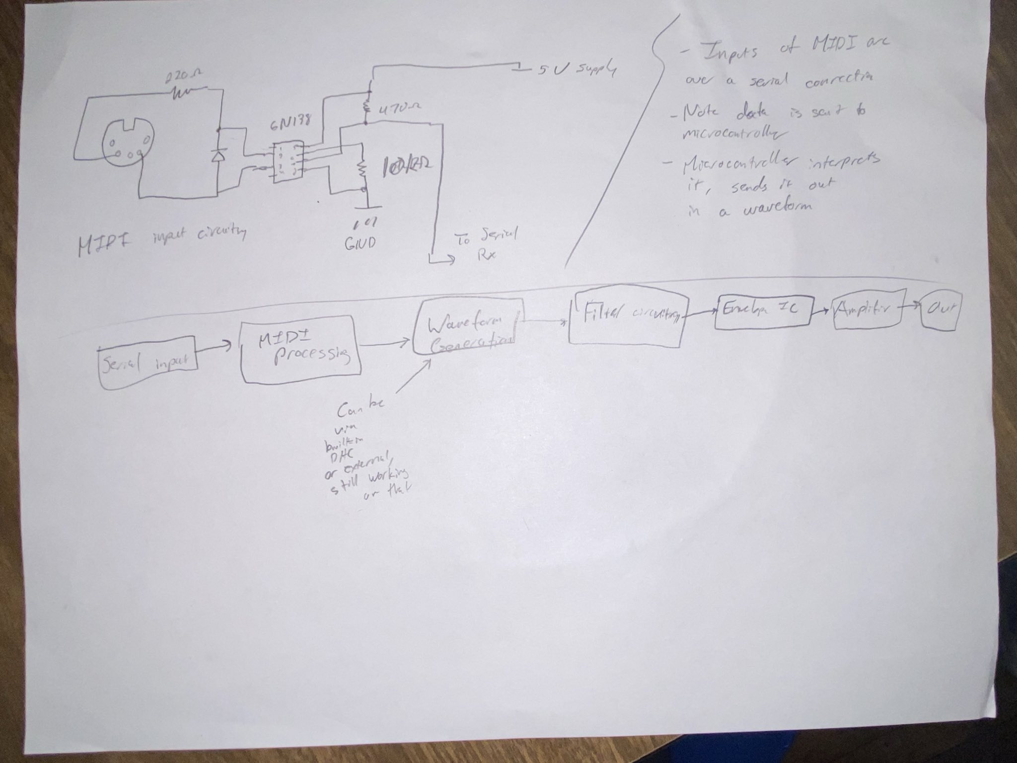
- Put together initial attempt for MIDI circuit on 10/2/2024
- Using an Arduino Mega, I was able to confirm that MIDI input was reaching the microcontroller, but it needs code changes to work
- Shown below: First attempt at wiring up the MIDI input

- TODO: 10/6/2024
- Investigate code and circuit configuration, see if something is up with serial capture
9/29/2024 Update
- Met with Synthesizer team on 9/28/2024
- Prepared CDR Documentation
- Parts arrived, started putting together larger schematic of the Synth
- With the other parts of the circuitry, I’ve started to think about how many Op-amp IC’s will be needed to filter power for the other IC’s
TODO 9/29/2024
- Calculate how many op-amps and resistors will be needed for power filtering going to IC’s
- Create schematic for routing of filtering circuitry and signal paths to and from Microcontroller
9/21/2024 Update
- Met with Synthesizer team on 9/14/2024
- Successfully generated square wave using Arduino
- Put together initial part list for MIDI input port integration with microcontroller
- Ordered parts for MIDI port integration, also ordered filter chip
- Decided to experiment with Teensy unit, due to clock speed limitations of Arduino
- A higher clock speed is necessary to make timer interrupts work for waveform generation, specifically for higher note frequencies. This is likely not the smartest method of waveform generation.
- Parts ordered:
- Low-pass filter IC, CEM3320
- MIDI conector
- Various resistors
- 1x Diode
- 1x 6N138 Optocoupler
- Accomplishments from last week:
- GitHub libraries under GPL are plentiful for MIDI generation with C on Arduino and other microcontrollers.
- Limits of Arduino waveform generation were found, and we are currently experimenting with a Teensy microcontroller.
- Upcoming To-Do list:
- Experiment with Arduino vs Teensy, explore limitations with Teensy onboard DAC
- Research readily available and compatible DAC chips, as onboard Teensy DAC doesn’t seem to like going above ~40 Hz when generating waves
- Could also be a bug in the code, needs to be investigated further
- Modify schematics used for MIDI port and Arduino integration for use with Teensy or Arduino for testing
- Since both boards are available for testing, we should explore using either for flexibility reasons
- Research alternative waveform generation methods in code.
- E.g., something that doesn’t involve the use of timer interrupts
- Look into code repo under OSHE for centralized storage/management of source code.
- Experiment with Arduino vs Teensy, explore limitations with Teensy onboard DAC
9/13/2024 Work Log
- TODO
- Do more research on MIDI libraries for Arduino.
- Research Arduino output maximums
- Research amplifiers based on signal specifications
- Get together with team for continued brainstorming and design work
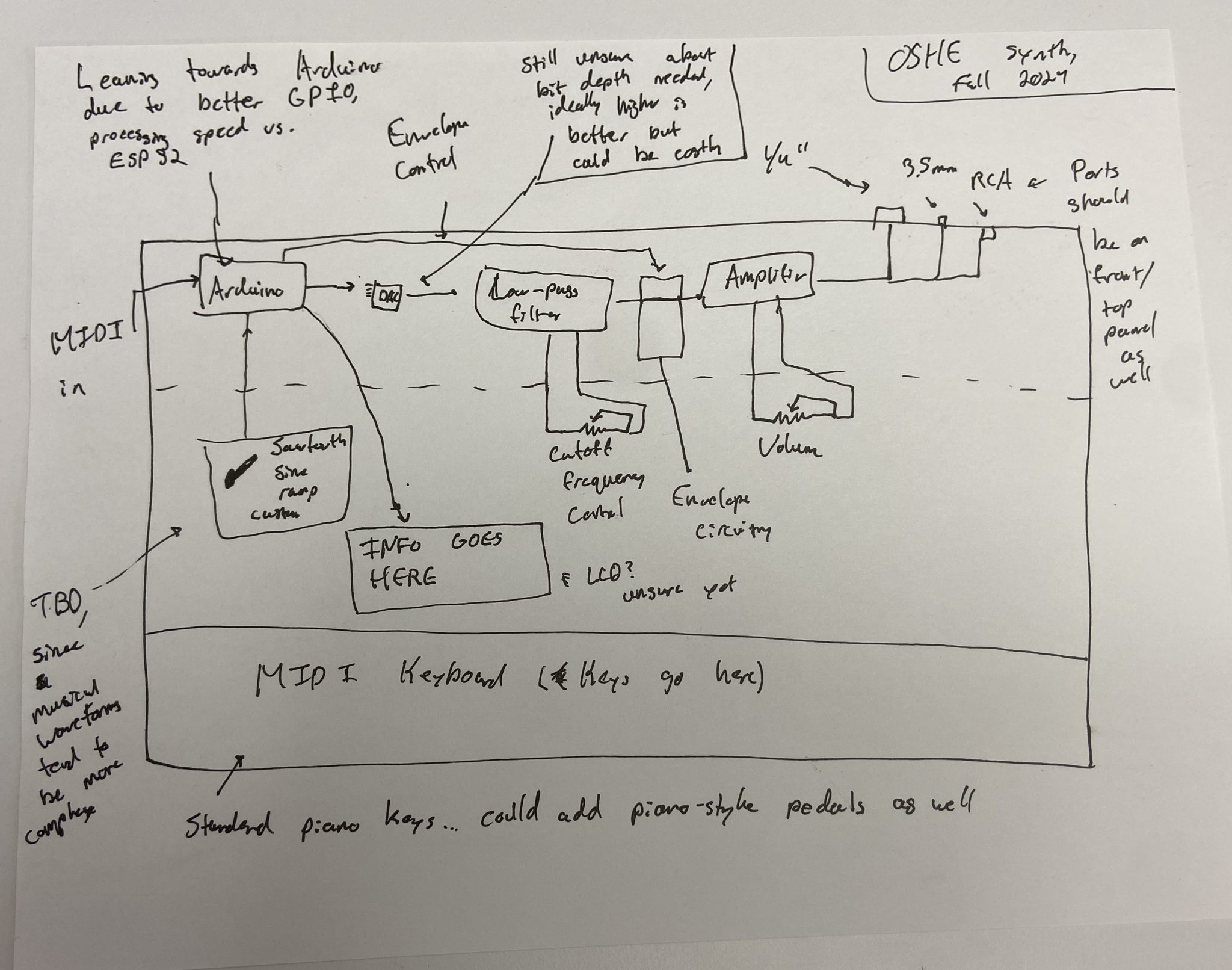
Above image: Rough Sketch of what the Synthesizer (may) look like at the end of the semester.