
4/20/2025
Device state at end of semester:
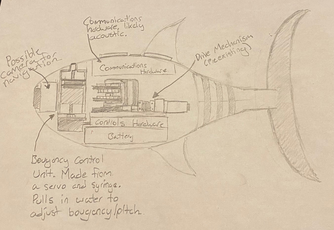
This is a cross section view of the robot, allowing view of the internals, the physical robot does not allow for easy viewing.
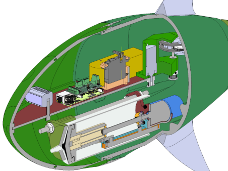
The fish body contains all working subsystems, but has some waterproofing issues, resulting in small leaks.
What was completed last week:
A final report draft was written, and design expo was attended.
My to-do list for this week (4/21-4/27):
Finish writing the final report and turn it in. I would also like to demonstrate the fully functional buoyancy control system and regain some design checkoff points.
Concerns for this week:
have no concerns for this week.
4/13/2025
What was completed last week:
The damaged buoyancy control motor was replaced, and the system was adjusted to protect against future overcurrent scenarios. I redesigned our main body seal to include a second o-ring. Our team prepared for design expo, making a poster and video.
My to-do list for this week (4/14-4/20):
My goals for this week are to succesfully present at design expo and reclaim lost points from design checkoff.
Concerns for this week:
I do not have concerns for this weeks work.
4/6/2025
What was completed last week:
The new fish body was constructed and partially sealed. The buoyancy system was printed and assembled. The system was also properly integrated into ROS with feedback. The design checkoff presentation was given.
My to-do list for this week (4/7-4/13):
My goals for this week are to work with my team to fix any issues experienced during design checkoff, this includes redesigning our main seal and replacing a fried motor.
Concerns for this week:
I do not have concerns for this weeks work.
3/30/2025
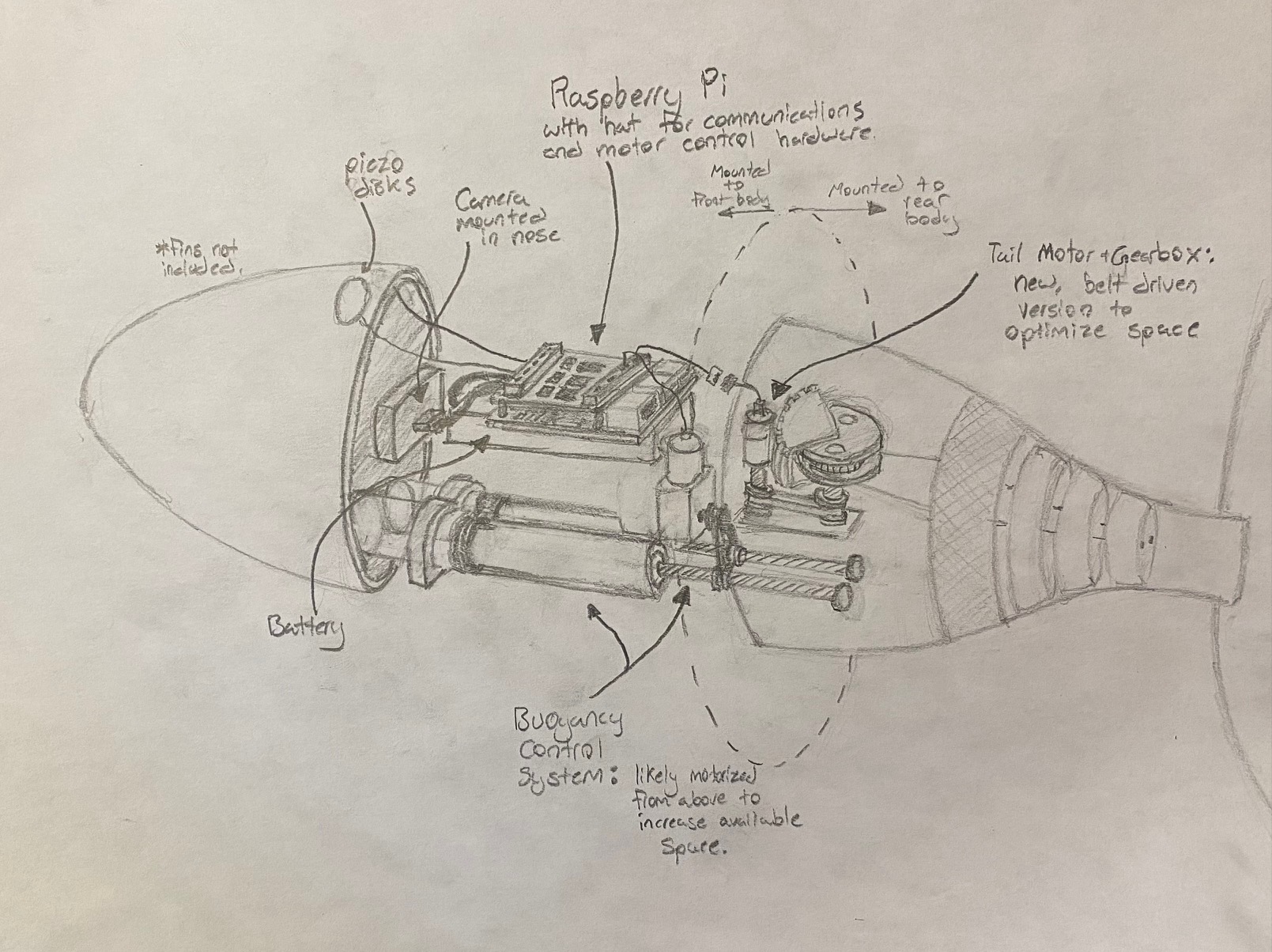
A sketch of what the project will look like at the end of the semester:
rather than a sketch, here is a half section of the robot with the buoyancy engine assembled inside of it. In the top hemishpere of the fish, the electrical and communications hardware will be housed.
The idea of the buoyancy system is the same as before, but the mechanical layout and part design went through a number of iterations. This final design is structually sound and easy to manufacture, assemble, and dissassemble.
What was completed last week:
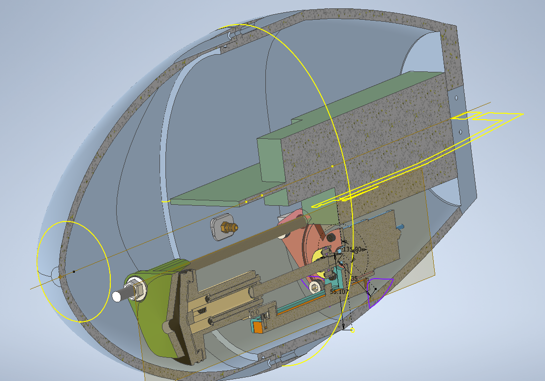
Much was completed last week, the final CAD assembly was constructed which fits perfectly inside the new body, maximizing buoyancy control volume. Additionally, the system was printed and constructed.
My to-do list for this week (3/31-4/7):
I would like to get the buoyancy control code integrated into ROS, this is yet to happen and is the last thing required before design checkoff. Also, I would like to prepare our presentation for design checkoff.
Concerns for this week:
My only concern this week is finding the necessary time to collaborate with teamates for code integration.
3/23/2025
What was completed last week:
Over the past week, the new body design was finalized, which allowed for the final CAD layout for the buoyancy system to be created. With this done, parts were ordered and construction of the system can now begin.
My to-do list for this week (3/23-3/30):
My goals for this week are to begin printing and assembling the buoyancy system inside the fish. Additionally, with the new ROS environment being set up, I would like tl get the buoyancy algorithm integrated.
Concerns for this week:
I do not have concerned for this weeks work.
3/16/2025
Image that demonstrates work conducted this week:

What was completed last week:
The buoyancy control algorithm was finished, with the specific code for implementing a PID controller being written. This required some learning but should effectively control the system.
My to-do list for this week (3/17-3/22):
I would like to get final confirmations on the buoyancy systems size contraints so that I may order the correct sized parts for implementation. Once this is done, I would like to make a simple test enclosure for testing the control algorhtm, as it will liklely not be until the end of the semester when the entire robot is assembled.
Concerns for this week:
My concerns involve determining the spacial contraints of the buoyancy system. This has been a bottleneck for much of my work this semester, and needs to happen this week given the remaining time in the semester.
3/9/2025
What was completed last week:
Over the past week, a rough draft for the buoyancy control algorithm was written. This code will need to be fine tuned with physical testing once integrated into the fish body.
My to-do list for this week (3/10-3/16):
My goals for this week are to work with my teamates to get the control python script integrated into our ROS network.
Concerns for this week:
I am not overly concerned for this weeks work, but I will need to make proper arrangements to collaborate with teammates.
3/3/2025
Image that demonstrates work conducted this week:
What was completed last week:
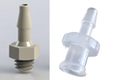
Last week, a system was researched, and parts selected, for installing a port in the fish body and routing the buoyancy control system through the port to the exterior of the fish. A hose fitting will be installed in the fish body, which will connect to the buoyancy system through a silicon tube and a barbed Luer Lock adapter, which is compatible with specific (but easy to find) syringes. These specific adapters are shown above. Additionally, research was done regarding control algorithms for the buoyancy control system.
My to-do list for this week (2/2-2/8):
Complete a python script implementing the buoyancy control algorithm. Also order the fittings described above.
Concerns for this week:
I don’t foresee having any major issues this week.
2/16/2025
What was completed last week:
The work completed last week involved preparation for critical design review, as well as experimenting with an internal frame to house the various components. Last week was not extremely productive, which was a consequence of having multiple midterm exams. For this reason, a number of decisions which need to be made are being moved to my to-do list for this week.
My to-do list for this week (2/16-2/22):
As mentioned above, work needs to be done regarding the placement and mounting of components inside the fish. Additionally, I would like to design a wall port for the buoyancy system to easily and reliable connect and disconnect from the fish body.
Concerns for this week:
My concern for this week is that without finalized dimensions for the thickness of the fish body, designing a filter housing/tubing connector may be delayed.
2/4/2025
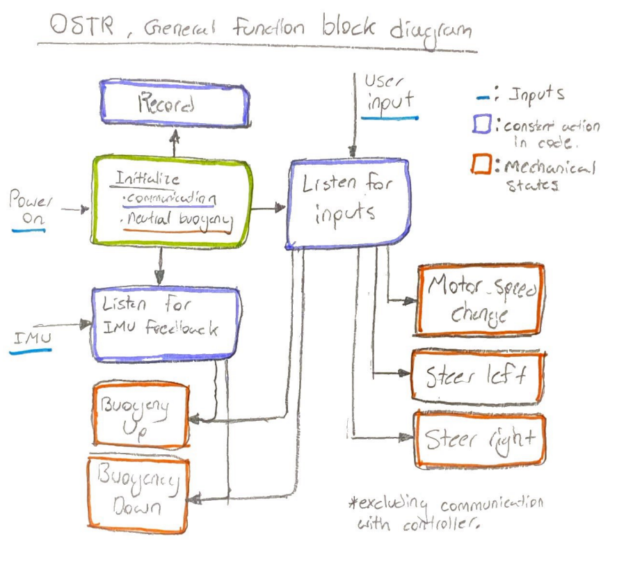
Diagram explaining the general operation of the device:
What was completed last week:
Last week, a final selection of parts was made for the buoyancy control system, specifically the motor. In regards to deciding a final layout for the internals of the fish, little progress was made. Completion of the fish body/shell is a prerequisite for determining the internal layout. Thus, this will likely need to be completed next week.
My to-do list for this week (2/2-2/8):
Provided the final body design for the fish, I would like to create mounting points for components and finalize the internal layout.
Concerns for this week:
My only concern for this week is that the fish body design may end up changing in the future if waterproofing measures prove to require iterations. This could potentially influence mounting points and layout decisions.
1/26/2025
What was completed last week:
Last week I 3D modeled multiple assemblies of different buoyancy control system configurations. They include different hardware layouts, and different drive motor positions. This will make our lives easier when we go to integrate the system into the new fish body as we will have to make zero, or slight alterations to whichever configuration works best. I began compiling specific parts lists for each configurations, however this will need to be finished on the onset of this week.
My to-do list for this week (1/26-2/2):
Finish parts lists for buoyancy configurations, work towards finalizing internal layout of the fish.
Concerns for this week:
My concerns for this week are that we may apprach a sort of gridlock situation with the fish body. The body size depends on the size of the internals, but the size of the internal buoyancy control system depends on how large the fish is. Luckily, there seems to be a size contraint with the fish body seal, so this will likely be the deciding factor that allows progress to be made.
1/22/2025
My sketch of what the project may look like at the end of Spring 2025:
My to do list for the coming week (1/23-1/30):
Make CAD Assemblies and parts lists for buoyancy configurations.
- belt driven
- in line motor
I have no concerns for this week. Determining the final buoyancy hardware layout is difficult without knowing exacly what space is available. So, the purpose of this week’s work is to make a few different layouts that we can pick from which share hardware. Then when the time comes to integrate buoyancy, we will just have to tweak mounting positions.
9/29/2024
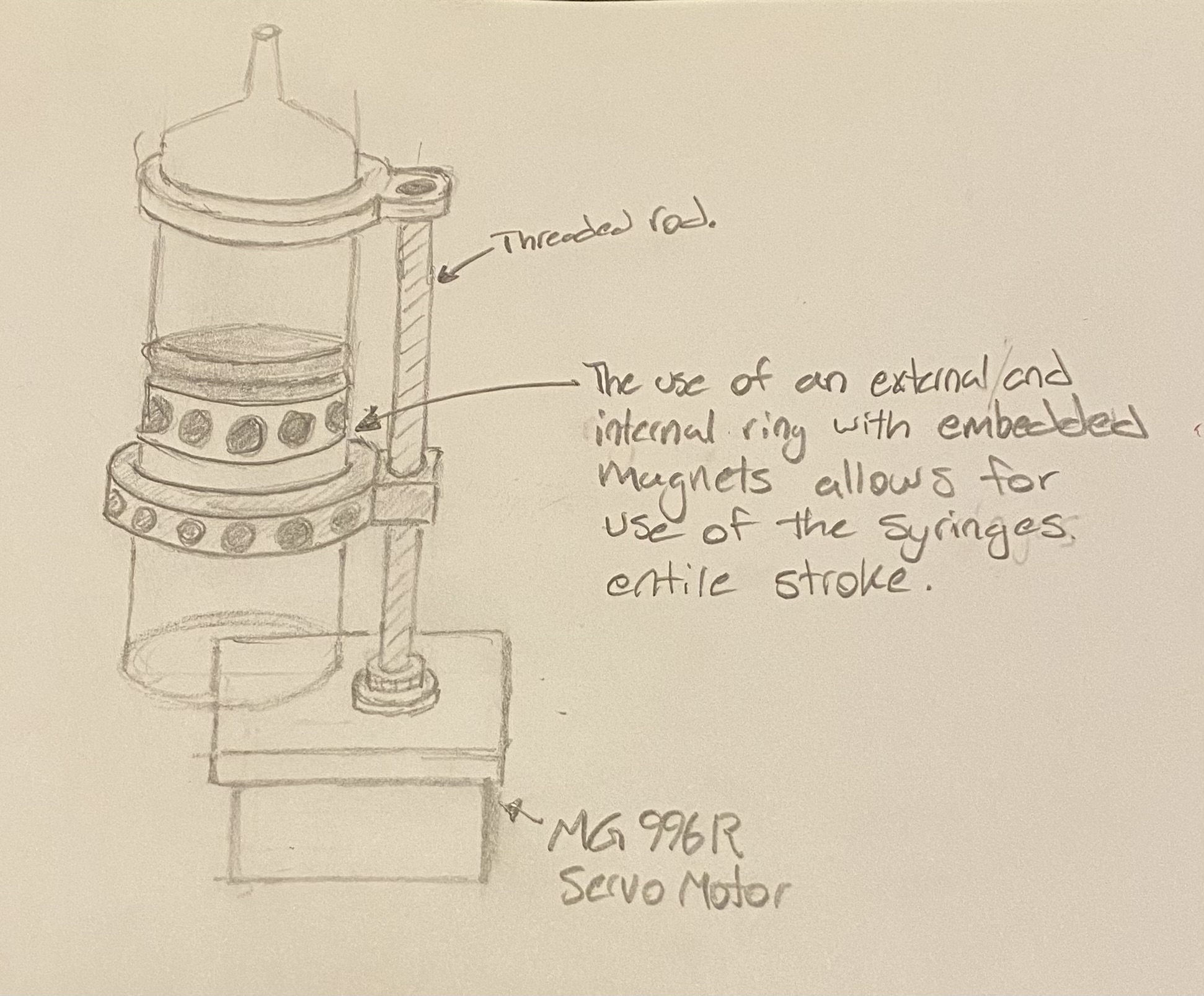
The operation of our device can be roughly illustrated in the diagram below:
The focus of my work had been on the buoyancy control system, a more detailed diagram of this system is shown below. The system pulls water in and out of a syringe to control the buoyancy of the robot. By placing the system in the nose of the fish, it can also be used to adjust the pitch of the robot. The system shown below uses magnets to transfer force from the threaded rod to the syringe plunger. This allows the plunger to travel along the full stroke of the syringe, since the threaded rod is located on the exterior of the syringe. When the rod is inside the syringe, the system is limited to 50% of the syringes original stroke (the rod cannot go through the plunger seal).
I plan for this system to operate in 2 states:
- Autonomous Neutral Buoyancy Mode: maintains a stationary vertical position using feedback from the IMU.
- Manual Control Mode: syringe motion is controlled via input from a controller.
What I was able to complete last week:
- Received parts and began construction of the buoyancy control unit. Due to other responsibilities, I was unable to complete the construction.
My to do list for the coming week:
- Finish assembling the buoyancy control unit.
- Research (and purchase?) IMU to test buoyancy control
- Get an accurate/current weight distribution of the robot so I can determine optimal size and placement of the final buoyancy control system
My concerns for this week:
- Time, I have been very busy and need to adjust my responsibilities to allocate more time towards the project.
- 9/22/2024
- What I was able to complete last week:
- CAD design for buoyancy control unit
- *currently waiting on parts for physical construction
- My to do list for the coming week:
- Construct the buoyancy control unit prototype
- Research (and purchase?) IMU to test buoyancy control
- Get an accurate/current weight distribution of the robot so I can determine optimal size and placement of the buoyancy control system
- My concerns for this week:
- Waiting on parts I ordered
9/13/2024
My sketch of what the project may look like at the end of the semester:
My to do list for the coming week (9/15-9/21):
Finish designing and build a functional buoyancy control prototype.
- Built inside a common syringe
- powered by an inexpensive servo
- Rough responsive control with an IMU (if parts are available)
- Able to be manually controlled
The unit will likely use a servo to turn a threaded rod which drives a syringe up and down, pulling water in and out of the robot. After filling the syringe half way with water, weights should be added to make the system neutrally buoyant. Thus allowing an equal range in positive and negative buoyancy adjustments.
My concerns for this week:
- Finding parts to build the prototype