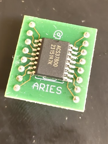
WEEK 4 – Project Update 3


- PAST WEEK:
- Soldered the our system’s primary IC, the power sensing module, to a breakout board to allow for further testing and implementation.
- Re-imagined power routing scheme to ensure correct functionality.
- TODO:
- Integrate the necessary modules to run DC consumption tests on a breadboard.
- This will allow us to confirm communication protocol between the Arduino and the IC.
- Integrate the necessary modules to run DC consumption tests on a breadboard.
- CONCERNS:
- I am worried that we are making slow progress. In the coming week I will devote more hours to this project than I have in the past week.
WEEK 4 – Project Update 2
- PAST WEEK:
- We collectively determined that the current PCB prototype has some glaring design flaws and it is not worth dedicating effort to diagnosing/fixing physical issues.
- The issues with I2C communication were likely electrical routing issues rather than software.
- Ordered new components to enable breadboard testing of full system components.
- TODO:
- Rewrite code to communicate via SPI for new board.
- Test smaller programming subsystems that do not depend on new PCB (i.e. webserver hosting)
- CONCERNS:
- Designing and ordering a new PCB will take a lot of time.
- Software is CRUCIAL for a working final product and it will be at least a couple of weeks before comprehensive testing can be conducted.
WEEK 3 – Project Update 1

- TODO:
- Diagnose the reason for 0 information transfer on the I2C bus between MCU and IC.
- Review electrical diagrams for PCB.
- Review I2C documentation for Arduino’s Wire library.
- Correct pin assignments in the Arduino software.
- Write “Hello world” program that will provide voltage and amperage levels to a user via serial terminal.
- Establish communication on the I2C bus.
- Parse IC’s register information into human-readable floating point values.
- Diagnose the reason for 0 information transfer on the I2C bus between MCU and IC.
- CONCERNS:
- My initial testing of the system software yielded 0 transfer of information between the MCU and the IC. This could mean one of three things:
- Power monitor IC is fried and must be replaced.
- The IC has been soldered to the board in the wrong orientation.
- The software has been written incorrectly.
- My initial testing of the system software yielded 0 transfer of information between the MCU and the IC. This could mean one of three things:
